Abstract
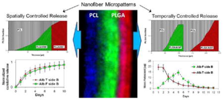
Controlled molecule release from scaffolds can dramatically increase the scaffold ability of directing tissue regeneration in vitro and in vivo. Crucial to the regeneration is precise regulation over release direction and kinetics of multiple molecules (small genes, peptides, or larger proteins). To this end, we developed gradient micropatterns of electrospun nanofibers along the scaffold thickness through programming the deposition of heterogeneous nanofibers of poly(ε-caprolactone) (PCL) and poly(D,L-lactide-co-glycolide) acid (PLGA). Confocal images of the scaffolds containing fluorophore-impregnated nanofibers demonstrated close matching of actual and designed gradient fiber patterns; thermal analyses further showed their matching in the composition. Using acid-terminated PLGA (PLGAac) and ester-terminated PLGA (PLGAes) to impregnate molecules in the PCL-PLGA scaffolds, we demonstrated for the first time their differences in nanofiber degeneration and molecular weight change during degradation. PLGAac nanofibers were more stable with gradual and steady increase in the fiber diameter during degradation, resulting in more spatially confined molecule delivery from PCL-PLGA scaffolds. Thus, patterns of PCL-PLGAac nanofibers were used to design versatile controlled delivery scaffolds. To test the hypothesis that molecule-impregnated PLGAac in the gradient-patterned PCL-PLGAac scaffolds can program various modalities of molecule release, model molecules, including small fluorophores and larger proteins, were respectively used for time-lapse release studies. Gradient-patterns were used as building blocks in the scaffolds to program simultaneous release of one or multiple proteins to one side or, respectively, to the opposite sides of scaffolds for up to 50 days. Results showed that the separation efficiency of molecule delivery from all the scaffolds with a thickness of 200 μm achieved >88% for proteins and >82% for small molecules. In addition to versatile spatially controlled delivery, micropatterns were designed to program sequential release of proteins. The hierarchically structured materials presented here may enable development of novel multifunctional scaffolds with defined 3D dynamic microenvironments for tissue regeneration.
1. INTRODUCTION
Scaffolds made from nanofibrous materials using electro-spinning techniques have been increasingly used for various tissue constructs, including those for replacement and regeneration of intervertebral disk, meniscus, annulus fibrosus, blood vessels, bone, and cartilage.1–9 The advantages of using nanofibrous scaffolds for tissue engineering include their load-bearing functionality, porous structure, and nano- to microsized fibers, similar in the length scale to native extracellular matrix (ECM), to guide cell adhesion and proliferation.10–14 The versatile use of electrospinning with a variety of natural and synthetic degradable polymers offers a large repertoire for tissue engineering and drug delivery applications.15–17 Additionally, electrospun biomaterials provide a wide range of mechanical and chemical properties via fiber composition, diameter, distribution, and porosity, through control over a panel of engineering parameters in the process.2,17–19 Further, collection of nanofibers onto a rotating mandrel or other collectors with specialized surfaces can result in structural and mechanical anisotropy for the applications of vascular or fibrous tissue engineering.20,21
To guide regeneration of tissue structure and function, an ideal scaffold for tissue regeneration should also provide molecular cues, in addition to structural support, mechanical properties, and biodegradable features. To incorporate regenerative or therapeutic molecules into biomaterials, various methods such as adsorption and covalent binding, encapsulation, and addition during scaffold formation, have been developed to sustain molecule release.22–24 A further step could be moving from static cues of one molecule toward delivery systems that reproduce more closely the dynamically evolving microenvironment occurring in natural ECM.25 Using mainly biodegradable particles, such delivery systems incorporating molecules could offer distinctive advantages such as regulation of release rate while protecting their molecule cargo during all the stages of tissue regrowth.26,27
Growing evidence has shown that tissue morphogenesis is coordinated by the spatial arrangement and temporal duration of multiple factors working in concert in the three-dimensional (3D) ECM.28 Though the fundamental principles for regulating the assembly of cells into the functional tissues are far from being well-understood, the main aspects which should be taken into account in delivery of growth factor or other molecules are (i) concentration–duration relationship, (ii) stable concentration gradients, (iii) multiple factor delivery, and (iv) spatial patterning.29–33 Recent advances in designing functional biomaterials attempt to harness some of these molecule regulatory mechanisms for tissue regeneration or other therapeutics.27,31 For precise regulation, recent developments have demonstrated the benefits of using micro- and nanostructures.34–37 The majority of newly developed molecule-impregnated scaffolds are capable of achieving sustained or temporally controlled molecule release. Fewer techniques, however, are available to engineer 3D scaffolds that define spatial organization of molecules or control release on the scales of both space and time. Control of where a molecule acts can strongly contribute to providing spatially complex arrangements of cells in length scales ranging from nano/micrometers to centimeters. The spatial control over release is also critical to coordinate cell behaviors for tissue pattern formation.27,34 Selective release of molecules that target specific cell types or tissue formation without influencing the activity of other cell populations or tissue functions is important to establish both in vitro physiological tissue models and in vivo tissue regeneration.31,38,39 Patterning or segregation of molecule delivery materials can be useful to spatially confine biomolecules.40 Take together, to meet various physiological needs of different cell types during tissue regrowth, a 3D scaffold should present a multitude of regenerative biomolecules in a sustained manner at defined locations.
Recently, strategies that use electrospun fibers to encapsulate and deliver molecules have been established.24,41 Due to inherently high surface area of electrospun materials, nanofiber constructs allow high molecule loading and efficient release in situ. However, the developed techniques have been limited to tune molecule release kinetics, and often, the structure and property of electrospun fibers are compromised to facilitate molecule encapsulation. We thus report a new strategy of design electrospun constructs, which utilizes micropatterns of nanofiber to spatially or spatiotemporally control delivery of molecules. We previously demonstrated the development of a double-electrospinning system that used a rotating mandrel collector to produce constructs composed of interpenetrating networks of nanofibers with diverse nanofibers in a tailored proportion to achieve anisotropic mechanical properties and engineered surfaces.20 By further developing the technique to program micropatterns of molecule-impregnated nanofibers, the present study aimed to demonstrate electrospun composite scaffolds with capability of selectively releasing molecules in a spatially and temporally controlled manner. Herein, heterogeneous nanofibers composed of degradable polymers poly(ε-caprolactone) (PCL) and poly(D,L-lactide-co-glycolide) acid (PLGA) have been used to form scaffolds with compositional and biochemical gradients along the scaffold thickness. Using PLGA nanofibers to encapsulate small molecules or proteins, we have characterized compositional and morphological changes as well as degradation behaviors of these composite scaffolds for up to 50 days in vitro.
2. MATERIALS AND METHODS
2.1. Materials
LACTEL 50:50 poly(D,L-lactide-co-glycolide) acid with a carboxylate end group and intrinsic viscosity of 0.67 dL/g, hereinafter referred to as PLGAac, was purchased from DURECT Corp. (Pelham, AL). PURASORB 50:50 poly(D,L-lactide-co-glycolide) acid with an ester end group and intrinsic viscosity of 0.32–0.48 dL/g, hereinafter referred to as PLGAes, was obtained from Purac Biomaterials (Lincolnshire, IL). PCL with a molecule weight of 80 kDa, chloroform (CF), N,N-dimethylformamide (DMF), methylene chloride (MC), methanol (MeOH), 1,1,3,3,3-hexaflouro-2-propanol (HFIP), sodium phosphate (NaH2PO4), sodium phosphate dibasic (Na2HPO4), and sodium azide were all purchased from Sigma Aldrich Inc. (St. Louis, MO). Polymers were used as received. Solvents were of analytical grade and used without any further purification. Isotonic phosphate buffer solution was prepared by mixing a 0.13 M solution of NaH2PO4 with 0.002% sodium azide and a 0.13 M solution of Na2HPO4 with 0.002% sodium azide, and then adjusting pH and osmolarity to 7.4 and 290–300 mosmol/L, respectively. Sodium azide was used to prevent bacterial contamination.
Fluorescent dyes, rhodamine 123 (Rh123) with green fluorescence, rhodamine-B (RhB) with red fluorescence, coumarin with blue fluorescence, as well as fluorescently labeled proteins, fluorescein isothiocyanate conjugate bovine serum albumin (AlbF) with green fluorescence and tetra-methyl-rhodamine isothiocyanate conjugate bovine serum albumin (AlbT) with red fluorescence were all obtained from Sigma Aldrich. The properties and uses of the fluorescent molecules and albumins are listed in Table S1.
2.2. Preparation of Electrospinning Solutions
PCL was dissolved in 75/25 CF/DMF at a concentration of 10% (wt). For both PLGAac and PLGAes, the pre-spinning polymer solutions were prepared by dissolving the polymer in the mixture of HFIP and DI water with a ratio of 7:1 (vol) and a final concentration of 17% (wt). To visualize the compositional gradient across the thickness of electrospun scaffolds and to characterize the molecule release profile, fluorescent dyes or fluorescently labeled albumins were added to pre-spinning solutions. Deionized (DI) water was used to dissolve fluorescent dyes. A solution of Rh123 or RhB with a concentration of 1 mg/mL was prepared with DI water, and then mixed with HFIP (7:1). Subsequently, the mixture was used to dissolve PLGAac and PLGAes. A PCL/coumarin pre-spinning solution was obtained by dissolving the polymer at a concentration of 8% (wt) in a ternary solvent mixture of MC/DMF/MeOH with a ratio of 5:3:2 (vol), where MeOH served as the carrier for coumarin. This was done by first dissolving 10 mg of coumarin in 300 μL of DI water to obtain the stock solution, then adding MeOH to the stock solution to obtain a 5 mg/mL solution of coumarin, and finally preparing the pre-spinning solution with the ternary solvent mixture. To prepare PLGAac nanofibers for in vitro release of fluorescent-labeled albumins, 5 mg of AlbF or AlbT was dissolved in 90 μL of DI water. Then, 630 μL of HFIP was added to the solution, forming a mixture to dissolve 220 mg of PLGAac, resulting in a 17% (wt) polymer solution. The overall content of albumin was 2.3% (wt) with respect to the mass of the dry polymer. During the entire process, the dye-containing solutions were always shielded from light to preserve the activity of fluorescent species.
2.3. Double-Electrospinning Process
The electrospun composite with the compositional gradient of distinct materials across the composite thickness was prepared through programming the sequential and/or simultaneous electrospinning processes of PCL and PLGA on a rotating mandrel collector, using a modified double-electrospinning system previously described by us.20 Briefly, a layer of PCL nanofibers, an intermixed layer of PCL and PLGAac (or PLGAes) nanofibers, and a layer of PLGA electrospun fibers were deposited in sequence on the grounded cylindrical aluminum collector. The design of the compositional patterns along the scaffold thickness was achieved by controlling 3D movements of a collector, in coordination with separately programmed spinning processes. The cylindrical collector, 8 mm in diameter, rotated at a constant velocity by a brushless rotating electric motor (Oriental Motor US, Torrance, CA). Each solution was individually stored in a 5 mL syringe. The syringe was connected to a blunt-ended needle that served as a charged spinneret. Each spinneret placed at the opposite side of the rotating collector was perpendicularly oriented with respect to the principal axis of the collector, and connected to a separate high voltage power supply (Gamma High Voltage Research Inc., Ormond Beach, FL). Both spinnerets moved in concert over an 18 cm path with a speed of 5 m/s along the collector mandrel which was under the control of a linear motorized stage (EZS3D025-C, Oriental Motor). The feed rate of each solution varied independently via separate syringe pumps (New Era Pump Systems, Farmingdale, NY) during the course of deposition. The electrospinning flow rates were determined before for each solution in order to form defect-free nanofibers. These flow rates, 0.6 mL/h for PLGA fibers and 1.1 mL/h for PCL fibers, defined the maximum flow rates. The collector geometry, the concentration of polymer solutions, and apparent density of pure PCL and PLGA electrospun nets were used to establish a correlation between the feed rate and the deposition rate of each polymer per unit of surface area. Detailed information of the solution compositions and electrospinning parameters is listed in Table 1.
Table 1.
Characteristics of Polymer/Dye Solutions and Electrospinning Parameters
| polymer | loaded dye | solvent mixture | polymer conc. [%wt] | dye content [%] wtdye/wtpol. | electric voltage [kV] | work distance [cm] | feed rate [mL/h] |
|---|---|---|---|---|---|---|---|
|
PLGAac PLGAes |
/ | HFIP/water 7/1 vol. |
17 | / | 26 | 20 | 0.15–0.6 |
|
PLGAac PLGAes |
Rh123 RhB |
HFIP/water 7/1 vol. |
17 | ~0.012 | 24 | 20 | 0.15–0.6 |
| PLGAac | AlbF AlbT |
HFIP/water 7/1 vol. |
17 | 2.23 | 22 | 20 | 0.15–0.6 |
| PCL | / | CF/DMF 3/1 vol. |
10 | / | 26 | 24 | 0.3–1.1 |
| PCL | Coumarin | MC/DMF/MeOH 5/3/2 vol. |
8 | ~0.05 | 20 | 20 | 0.3–1.1 |
The electrospinning process was performed at room temperature in open atmosphere with a relative humidity of 20–25%. The overall thickness of the electrospun nets was measured using a micrometer screw gauge. The design thickness of PCL-PLGA materials was 150 μm; samples with actual thickness outside of the 135–165 μm range were discarded. When fluorescent molecules were used, the entire apparatus was shielded from light to preserve the dyes. Electrospun samples were stored in a desiccator and kept in the dark.
2.4. Characterization of Nanofiber Morphology and Compositional Micropattern
The morphology of electrospun fibers was observed using a JSM-6480LV scanning electron microscope (SEM) (JEOL Ltd., Japan) at 5.0 kV. Samples were sputter-coated with gold prior to analysis. Scaffolds loaded with fluorescent dyes were used for characterizing compositional micropatterns. They were embedded in cryo-optimum-cutting-temperature compound (Andwin Scientific, Germany) or in paraffin for sectioning. A series of 15-μm-thick sections were obtained with a cryostat or rotary microtome for confocal imaging. The cross sections of the nanofiber scaffolds loaded with fluorescent species were examined under a Scanning 510 confocal microscope equipped with AR, HE/Ne, and diode laser sources (Carl Zeiss, Germany). Images were used to assess the dye distribution in the nanofibers and along the thickness of the scaffolds. Compositional profiles of scaffolds were determined by measuring the color intensity of dyes in the confocal images, using ImageJ software (National Institutes of Health, Bethesda, MD). Fluorescent profiles were obtained by averaging at least 6 profiles acquired from 2 different samples. Fluorescent intensity values at each position of the cross section were averaged and reported as mean ± standard deviation.
2.5. Thermal Analysis
Thermal analyses were performed using a differential scanning calorimeter (DSC) (DSC 204 F1 Phoenix, Aurora, IL, USA) under flushing nitrogen (100 mL/min). Each sample was first heated from −110 to 120 °C with an incremental rate of 10 °C/min and held at each temperature for 3 min. The sample was then slowly cooled to −110 °C with liquid nitrogen at a cooling rate of 5 °C/min and reheated for a second scan to 120 °C at a rate of 10 °C/min. For the PCL-PLGA composites, the glass transitions of PLGAac and PLGAes were measured from the first heating scans. The transformation was clearly visible and was accompanied by an appreciable enthalpic relaxation associated with aging of the polymer.42 Therefore, the onset point and inflection point were both reported. In the second heating scan, the glass transitions of PLGA were not visible, due to the melting peak of PCL. The peak temperature of the melting transition of PCL was recorded and melting peaks of PCL in pure PCL sample and PCL-PLGA samples were quantitatively determined by integration. The crystallinity degree of PCL (αPCL) was determined by comparing the melting enthalpy of PCL (ΔHPCL) for PCL nanofibers with the theoretical value of a sample with 100% crystalline PCL (ΔH100%), which equals to 139.4 J/g.43 Thus, αPCL = 100 × (ΔHPCL/ΔH100%). The melting enthalpy was determined by calculating the area of the endothermic melting peak. Under the assumption that melting enthalpy of PCL remained constant in PCL-PLGA samples, αPCL was used to determine the fraction of PCL nanofibers.
2.6. Hydrolytic Degradation Analysis
Hydrolytic degradation analyses were performed on electrospun scaffolds at 37 °C in phosphate buffer solution (pH = 7.4) under constant mild agitation up to 6 weeks. For each electrospun net, specimens were immersed in 5 mL of phosphate buffer solution in separate test tubes. Triplicate samples for each experimental condition were withdrawn at a predetermined time, washed in DI water, and dried under vacuum in a desiccator for 48 h. Then, the samples were weighed on an analytical balance. Using the gravimetric method, weight loss of each sample was determined. Three to five specimens were tested for each sample. The measured values were averaged and reported as mean ± standard deviation. Corresponding changes in nanofiber morphology were monitored using SEM micrographs. Molecular weights of PCL, PLGAac, and PLGAes were determined by gel permeation chromatography (GPC) (GPCmaxTM, Viscotek, Houston, TX) with a differential refractive index (RI) detector (Viscotek 3580), and a set of Viscotek Viscogel columns with THF as the eluent at 30 °C. The analytical GPC was calibrated using monodisperse polystyrene standards. Molecular weights of the as-spun scaffolds and those after each degradation time were measured. The GPC curves of the materials showed a bimodal distribution. The overlapped peaks were then deconvoluted into two separate asymmetric peaks with the least-squares method and assigned to PCL and PLGAac (or PLGAes). The peak-fitting parameters were conditioned using the peak parameters of the parent materials. The molecular weights corresponding to individual deconvoluted peaks were also determined.
2.7. Release Profile Characterizations
For molecule release characterizations, the circular samples with 24 mm diameter were cut from PCL-PLGAac and PCL-PLGAes scaffolds loaded with fluorescent dye or fluorescently labeled albumin. For each experimental condition, three samples were used for analyses. Scaffold samples were placed in a custom-made diffusion-test system in which a sample was sandwiched between two reservoir chambers. Each side of the electrospun scaffolds thus faced a different reservoir filled with 1 mL of buffer solution. The reservoirs, SecureSeal hybridization chambers (Grace Biolabs, Bend, OR), tightly sealed the surface. Each reservoir had small holes for sampling and changing solutions. The holes were covered with silicone sealing tap during experiments to prevent evaporation. Thus, molecule movements between the reservoirs could only be through the pores of electrospun materials. Release tests were performed at 37 °C. Samples of buffer solutions in both reservoirs were collected every day during the first 16 days, and subsequently once a week in the case of long-term studies. After sampling, reservoir chambers were rapidly rinsed with DI water and refilled with fresh phosphate buffer. Samples of 200 μL in triplicate were analyzed in 96-well microplates with a Victor 2 microplate reader (PerkinElmer, Santa Clara, CA) to quantify the concentration and net amount of released Rh123, AlbF, and AlbT, according to their respective calibration curves. The geometry and porosity of the molecule-releasing scaffolds remained constant for all the experimental samples. For the designs with multiple molecules, as various fluorophores could be simultaneously released by the samples, the possibility of overlapping of fluorophore emission spectra was examined; no overlaps were found in the interested spectrum ranges. The measured values were averaged and reported as mean ± standard deviation. Additionally, a parameter that quantifies the efficiency of separation (S) was used to describe the scaffold’s capability of confining molecule release to one specific side of the scaffolds. For each molecule, the efficiency of separation between Side A and Side B, Smolecule_A-B, was defined as the percentage of the molecule released on Side A over the total amount of the molecule released on Sides A and B.
3. RESULTS
3.1. PCL-PLGA Scaffolds with Micropatterned Nanofibers Demonstrated Custom-Designed Compositional Gradients
Using the double-electrospinning apparatus with capability of programming 3D position of different nanofibers, we have formed multicomponent structures with tailored micropatterns. Figure 1 illustrates a structure which consists of a 25-μm-thick PCL nanofiber layer, a 100 μm interlayer with mixed nanofibers of PCL and PLGA, and a 25 μm PLGA nanofiber layer. The design shows a pattern of pure PCL and PLGA on the surfaces of the opposite sides, and an intermediate region in which the PLGA content varies gradually between 0% and 100% along with reversed change in the PCL content. The compositional gradient across the material thickness was achieved by gradually decreasing the feed rate of PCL to 0, while simultaneously increasing the feed rate of PLGA to the predetermined maximal value. The pattern was designed to produce scaffolds with equal amount of PCL and PLGA in weight.
Figure 1.
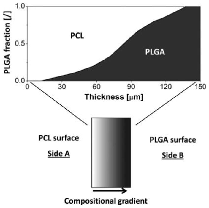
Schematic illustration of the cross section of a PCL-PLGA electrospun scaffold with internal compositional gradient. The fraction of PCL nanofibers (shown in white) decreases along the thickness of the material from 1 on the left side (PCL surface – Side A) to 0 on the right side (PLGA surface – Side B), while the PLGA fraction (shown in dark gray) increases along the scaffold thickness from 0 to 1.
To assess the actual composition of scaffolds, DSC analysis was used. Results were summarized in Table 2. The results demonstrated that the actual material composition closely matched the design. The comparison between the endothermic melting enthalpies of PCL in the scaffolds and the melting enthalpies of pure electrospun PCL was used to determine the actual amount of PCL and the PCL/PLGA ratio in the scaffolds. PCL nanofibers showed crystallization enthalpy of 55.9 J/g during cooling and melting enthalpy of −58.5 J/g in the second scan. As the melting enthalpy of 100% crystalline PCL is 139.5 J/g, the resulting crystallinity of electrospun PCL nanofibers was around 42%.
Table 2.
Thermal Properties of PCL and PCL-PLGA Electrospun Materialsa
| sample | PCL
|
|||||
|---|---|---|---|---|---|---|
| Tm (II scan) [°C] | ΔHPCL melting (II scan) [J/g] | PCL content (II scan) [%wt] | Tc (cooling) [°C] | ΔHPCL crystal. (cooling) [J/g] | PCL content (cooling) [%wt] | |
| PCL nanofibers | 60.0 | −58.5 | 100.0 | 27.1 | 55.9 | 100.0 |
| PCL-PLGAes | 61.3 | −31.9 | 54.5 | 27.9 | 29.7 | 53.1 |
| PCL-PLGAac | 59.1 | −32.2 | 55.0 | 26.7 | 30.5 | 54.6 |
| sample | PLGA
|
|||
|---|---|---|---|---|
| PLGA content (from melting) [%wt] | PLGA content (from crystal.) [%wt] | Tg (I scan, Onset) [°C] | Tg (I scan, Inflection) [°C] | |
| PCL-PLGAes | 45.4 | 46.9 | 35.2 | 38.5 |
| PCL-PLGAac | 45.0 | 45.4 | 37.8 | 39.7 |
Abbreviations: Tm, melting temperature; ΔH, heat of fusion; Tc, crystallization temperature; Tg, glass transition temperature; crystal., crystallization.
Results from the crystallization and melting enthalpies of PCL-PLGAes and PCL-PLGAac scaffolds revealed that the actual PCL content was around 55% in both cases. Therefore, the actual PLGA contents were around 45%. Also, the glass transition temperatures of PLGAac and PLGAes, determined from the inflection point in the first DSC scan curves of PCL-PLGA scaffolds, were 39.7 and 38.5 °C, respectively. We also noticed that the glass–rubber transition for PLGAes at the onset point started at 35.2 °C, below the working temperature of 37 °C, while the transition zone for PLGAac started at 37.8 °C, just above the working temperature.
In addition to the closely matching composition, confocal images of the cross sections of molecule-impregnated nanofiber materials further demonstrated that the compositional gradients of impregnated molecules matched the designed nanofiber micropatterns. Herein, PCL nanofibers were loaded with a blue fluorophore coumarin, while PLGAac nanofibers were loaded with red fluorophore RhB and/or green fluorophore Rh123. Figure 2 demonstrated the molecule patterns in a two-component scaffold and a three-component scaffold. Figure 2a showed the confocal image of a PCL-PLGAac material, in which PCL and PLGAac were loaded with blue and red fluorophores, respectively. The gradual increase in the red color intensity from the left to the right side of the image demonstrates the increase of PLGAac content across the material thickness, whereas the attenuation of blue intensity shows the reduction of the PCL fraction in the same region. Also, no red signals were found close to the surface on the PCL side, and no blue signals close to the surface on the PLGAac side. This reflects the pure polymer design in these regions. However, due to the saturation of fluorescent signals, the fluorescent profiles in the high intensity range could not be accurately assessed. Figure 2b illustrated the design of a three-component scaffold, where PLGAac nanofibers were used to impregnate two molecules in the respective regions: green Rh123 in the inner region and red RhB in the outer region of the scaffold. Similar to the pattern observed in the two-component scaffold, the fluorescent intensity profiles in the confocal image reproduced the designed micropattern across the scaffold thickness with accuracy except in the high intensity range where the fluorescent signals saturated beyond detection.
Figure 2.
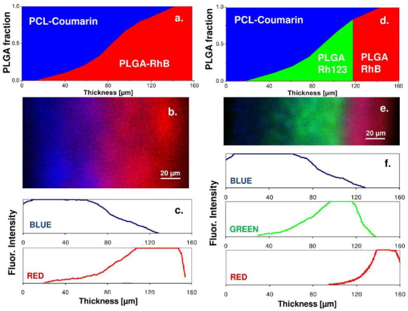
Design illustrations and confocal images of the gradient micropatterns over the thickness of PCL-PLGAac scaffolds. In the design illustrations (a,d) and confocal images (b,e), blue color shows PCL nanofibers loaded with fluorophore coumarin, red shows PLGAac nanofibers loaded with RhB, and green shows PLGAac nanofibers loaded with Rh123. The color intensity profiles (c,f), quantitatively determined from the confocal images, demonstrate the changes in the signal intensity of each fluorophore molecule across the sample thickness. Results demonstrate good agreement between the design patterns and the actual concentration profiles of the molecules or fibers.
3.2. Hydrolytic Analyses of PCL-PLGA Scaffolds Demonstrated the Different Degradation Behaviors and Morphological Changes of PLGAac and PLGAes
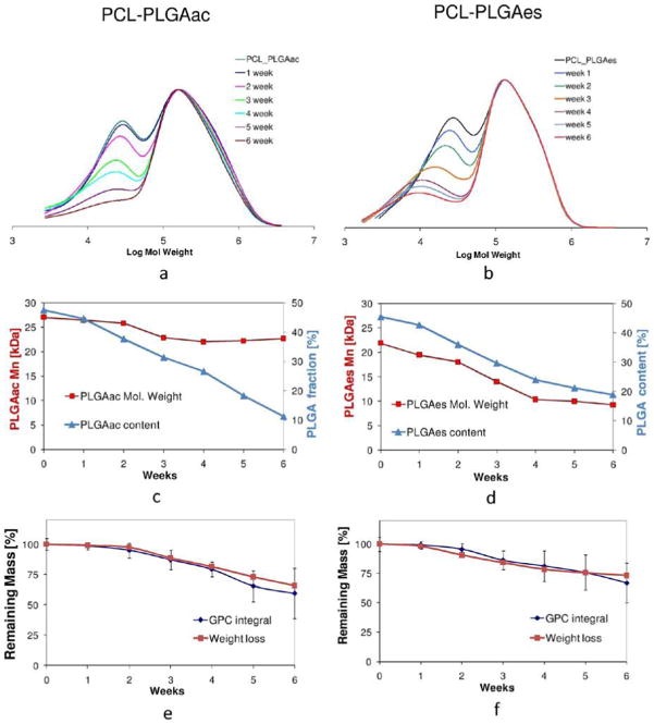
To compare hydrolytic degradation behaviors of PCL-PLGAac and PCL-PLGAes scaffolds, samples were analyzed with a gravimetric method for weight loss, GPC for changes in the polymer molar weight distribution, and SEM for nanofiber morphology. Results demonstrated significant differences between PLGAac and PLGAes during the 6-week hydrolytic degradation.
The SEM micrographs shown in Figures 3 and 4 demonstrated the evolution of PCL-PLGAac and PCL-PLGAes scaffolds during degradation. Figure 3a,b showed that the morphology and network of PLGAac nanofibers remained virtually unchanged after 1 week of degradation in buffer. During this period, the average fiber diameter increased about 25%, from 0.62 ± 0.27 μm to 0.78 ± 0.28 μm. After 3 weeks, PLGAac nanofibers exhibited a more significant increase in diameter with an average diameter of a few micrometers, and the fiber network was characterized by soldering-like attachments at the junctions (Figure 3c). The SEM images also showed that, by week 3, some fibers on the surface lost the smooth cylindrical morphology. Also, PCL nanofibers underneath PLGA fibers started to emerge in the SEM images, exhibiting unaffected cylindrical and smooth morphology. Overall, the deformed and swollen PLGAac nanofibers seemed to be collapsed onto, and wrapped around, the more stable PCL fibers after 3 weeks of degradation. After 5 weeks, the fibrous structure of PLGAac almost disappeared, and a film of PLGAac covered the web of PCL nanofibers which were unscathed after degradation (Figure 3d). From a macroscopic view, we found that PCL-PLGAac scaffolds remained flat and dimensionally stable in terms of the overall geometry and size, during the entire experimental period.
Figure 3.
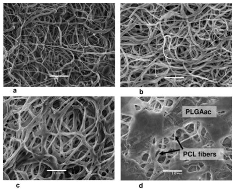
Representative SEM micrographs of the PCL-PLGAac nanofibrous scaffold with an internal compositional gradient. Images were taken from the PLGA side. (a) Morphology of as spun PLGAac nanofibers. (b–d) Changes in the nanofiber morphology after 1 week (b), 3 weeks (c), and 5 weeks (d) of degradation in phosphate buffer solution at 37 °C. The unchanged PCL nanofibers underneath the PLGAac layer were found after 5 weeks of degradation (d). Scale bar shows 10 μm.
Figure 4.
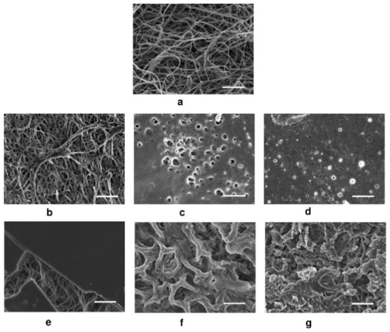
Representative SEM micrographs of the PCL-PLGAes nanofibrous scaffold with an internal compositional gradient. Images were taken from the PLGA side. (a). Morphology of PLGAes nanofibers as spun. (b–f) Changes in the PLGAes nanofiber morphology after 1 day (b), 3 days (c), 1 week (d), 2 weeks (e), 4 weeks (f) and 6 weeks (g) of degradation in phosphate buffer solution at 37 °C. The unchanged PCL nanofibers underneath the PLGAes layer were found in all these images (b–d). Scale bar shows 10 μm.
Compared to PLGAac, the morphology of PLGAes nanofibers was altered much more rapidly (Figure 4). After only 1 day exposure to buffer, the electrospun PLGAes nanofiber network started to collapse with extensive soldering-like attachments at the junctions (Figure 4b). Within one day, the average fiber diameter increased nearly 80%, from 0.50 ± 0.17 μm to 0.88 ± 0.10 μm. After 3 days, no fiber-like morphology remained in the PLGAes layer. The layer turned into a membrane with only an array of small circular open pores (Figure 4c) whose diameters continued to decrease in the first week (Figure 4d). At the end of the second week, the PLGAes layer was entirely restructured and became a solid substrate without pores lying on the bed of PCL nanofibers. Figure 4e demonstrated the structure of PCL fibers lying under a fractured portion of the PLGAes layer.
From then on, the surface of PLGAes layer appeared to be continuously eroded by the buffer, and after 6 weeks, a significant amount of material still remained on the surface (Figure 4f–g). Similar to PCL-PLGAac, in the PCL-PLGAes composites, the morphology and network structure of the nanofibers on the PCL side remained unchanged during the degradation process. From a macroscopic view, it was found that the PCL-PLGAes scaffolds shrunk and deformed bending toward the PLGAes side, which might be due to the loss of PLGAes pores reducing the volume of the PLGAes material.
To gain further understanding of the hydrolytic degradation processes of the composite scaffolds, we characterized changes in the overall weight and molecular weight of different PCL-PLGA scaffolds. Using GPC curves of the component polymers (Figure S1), we first determined the weight-average molecular weight (Mw), number-average molecular weight (Mn) and polydispersity (pdi) of pure PCL, PLGAac, and PLGAes materials. Obtained values were summarized in Table 3. These data were used to analyze the curves of PCL-PLGA composite scaffolds at different steps of the degradation process.
Table 3.
Molecular Weight and Polydispersity of the Polymer Useda
| polymer | Mw [kDa] | Mn [kDa] | pdi |
|---|---|---|---|
| PCL | 137 | 78 | 1.8 |
| PLGAac | 43 | 26 | 1.6 |
| PLGAes | 36 | 22 | 1.7 |
Abbreviations: MW, weight-average molecular weight; Mn, number-average molecular weight; pdi, polydispersity.
Figure 5 demonstrated the differences between PCL-PLGAac and PCL-PLGAes scaffolds in the GPC curve, molecular weight change, and weight loss during hydrolytic degradation. Both GPC curves exhibited a bimodal distribution. The peak at the higher molecular weights was assigned to PCL, whereas the peaks at lower molecular weights were assigned to PLGA. GPC results from both PCL-PLGAac and PCL-PLGAes materials (Figure 5a,b) showed that the PLGA peak gradually decreased and shifted toward lower molecular weights, while the PCL peak remained unaffected during the hydrolytic degradation. Using deconvolution analysis of GPC curves, the contributions of PCL and PLGA, the PLGA content in the scaffold, and the number average molecular weight of the polymer were determined. As shown in Figure 5c, the molecular weight of PLGAac slightly decreased between week 2 and week 3 before becoming steady at 21 kDa. The PLGAac content in the scaffold steadily dropped to approximately 22% of the original amount after 6 weeks. Compared to PCL-PLGAac, the molecular weight of PLGA in PCL-PLGAes scaffolds dropped more progressively from 22 to 9 kDa, suggesting molecular breakdown during the experimental period (Figure 5d). The PLGAes content decreased accordingly. However, when compared to PCL-PLGAac, there was a higher amount of PLGA content present in PCL-PLGAes scaffolds after 6 weeks, approximately 40% of the original amount of polymers. The weight loss curves for the PCL-PLGAac and PCL-PLGAes scaffolds were presented in Figure 5e and f, respectively. The remaining mass of the scaffolds was determined by the gravimetric method and by measuring the overall area under the GPC curve; the curves of weight loss for both materials are similar in shape. Overall, compared to PLGAac, PLGAes degraded more slowly, but underwent chemical breakdown during degradation, showing immediate reduction in molecule weight and faster loss of nanofiber morphology.
Figure 5.
GPC analyses of the as-spun PCL-PLGAac and PCL-PLGAes scaffolds and the scaffolds after hydrolytic degradation. (a,b) GPC curves of PCL-PLGAac and PCL_PLGAes. (c,d) Changes in number average molecular weight and remaining PLGA content determined by deconvolution of the GPC curves. (e,f) Overall remaining mass percentage of the scaffolds determined by the gravimetric method and measurement from GPC curves.
3.3. Spatially Controlled Release of Small Molecules from PCL-PLGAac and PCL-PLGAes Scaffolds
To assess the potential use of PCL-PLGAac and PCL-PLGAes materials for spatially controlled release of active molecules, we first performed release experiments using Rh123. PCL and PLGA/Rh123 solutions were electrospun to prepare scaffolds following the pattern described in Figure 1. Release studies were carried out in custom-made diffusion chambers with independently sealed reservoirs facing the two surfaces of electrospun samples, as illustrated in Figure S2.
The two sealed reservoirs filled with phosphate buffer solution were placed on the opposite sides of the electrospun scaffolds. The PCL side of the scaffold was set to face the buffer reservoir chamber on Side “A”; the Rh123-impregnated PLGA side was placed in contact with the buffer reservoir on Side “B”. Daily measurement results of the Rh123 dye concentrations in both reservoirs were shown in Figure 6.
Figure 6.

Double-sided release test on PCL-PLGAac and PCL-PLGAes with Rh123 impregnated in the PLGA fibers. (a) Release of Rh123 from the two surfaces of PCL-PLGAac scaffolds. (b) Release of Rh123 from the two surfaces of PCL-PLGAes scaffolds. The release was determined by measuring the fluorophore concentration in the chamber reservoirs. Herein, “Side B” indicates the fluorophore-loaded PLGA surface and “Side A” indicates the PCL surface.
Figure 6a demonstrated that the majority of the encapsulated fluorescent molecules were released from the PLGAac side. Thus, the electrospun PCL-PLGAac scaffolds demonstrated the capability of confining sustained molecule release to one side of the scaffolds. The separation efficiency of Rh123 between the two surfaces (SRh123_B-A) of the PCL-PLGAac scaffolds was 82 ± 5% during the 9-day release experiment. On the contrary, PCL-PLGAes samples displayed mixed release behavior. Figure 6b showed that more molecules were released from the PCL side, when compared to PCL-PLGAac. In addition, after day 3, the molecule concentration measured on the PCL side exceeded that on the PLGAes side. This resulted in a separation efficiency of ~50%; thus, no spatial separation of Rh123 between the two surfaces of the PCL-PLGAac scaffolds was found.
On the basis of the degradation and initial release results, the PCL-PLGAac scaffold was chosen for the release of biomolecules. Though interesting, PCL-PLGAes materials were not further used to design scaffolds for spatially or spatiotemporally controlled protein release in this study.
3.4. Spatially Controlled Protein Release from PCL-PLGAac Scaffolds
A variety of micropatterned composite scaffolds made up of PCL nanofibers and protein-impregnated PLGAac nanofibers were designed to demonstrate the versatile use of nanofiber micropattern for sustained release of one or two molecules with control in space and/or time scale. PLGAac nanofibers impregnated with fluorescently labeled albumins were prepared by one-phase, solution electrospinning. Albumin was dissolved directly in the polymeric solution prior to electrospinning and appeared to be homogeneously distributed in the PLGAac nanofibers (Figure S3).
3.4.1. Spatially Controlled, Sustained Release of a Protein
Figure 7 demonstrates the cumulative release of AlbT from the PCL-PLGAac electrospun scaffolds. The scaffolds were prepared according to the micropattern presented in Figure 2a. AlbT was impregnated in the PLGAac nanofibers. The scaffolds were characterized by a nanofiber gradient and thus AlbT gradient. Results showed that sustained release of AlbT was highly confined to the PLGAac side of the scaffolds (Side B), and the release of AlbT from the PCL surface (Side A) was limited. The separation efficiency for AlbT between side B and side A of PCL-PLGAac scaffolds was 90 ± 4%, higher than the efficiency for smaller molecules (i.e., fluorophores). Results also showed that approximately 88% of the total amount of entrapped AlbT was released during the 50-day experiment. This estimation was made using an overall PLGAac content in the scaffold equal to 48%, as determined from DSC analysis of this specific AlbT-loaded PCL-PLGAac scaffold. Approximately 20% of the total loaded proteins were released in the first 24 h, 80% were released in 9 days. After day 9, the low-slope release curve indicated a small amount of sustained release at a constant rate (about 1% per week).
Figure 7.
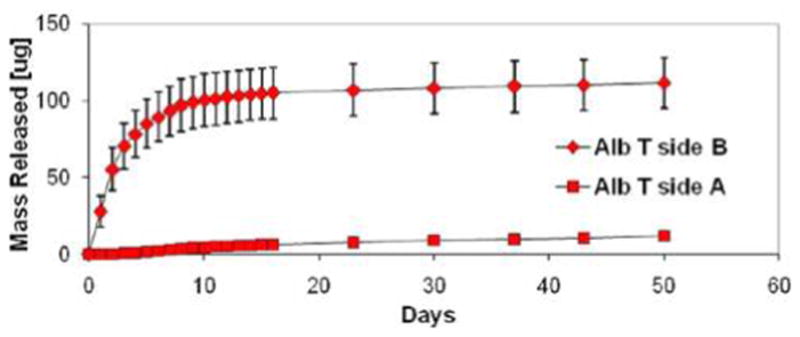
Cumulative release of AlbT from the two surfaces of PCL-PLGAac composite scaffolds. The scaffolds were prepared following the compositional pattern introduced in Figure 1. AlbT was encapsulated in PLGAac and it was released mainly from the PLGAac-rich side. “Side A” refers to the PCL-rich side, whereas “Side B” refers to the AlbT-loaded PLGAac side. “AlbT” represents tetra-methyl-rhodamine isothiocyanate conjugate bovine serum albumin with red fluorescence, and “ALbF” represents fluorescein isothiocyanate conjugate bovine serum albumin with green fluorescence.
3.4.2. Sustained Releases of Two Proteins to One Side
We also demonstrated a different pattern able to provide concurrent release of two proteins from the same side of the PCL-PLGAac composite scaffolds. As illustrated in Figure 8a, PLGAac nanofibers in the inner part of the scaffolds were loaded with AlbF (green), while those in the outer region were loaded with AlbT (red). Results of cumulative release curves (Figure 8b) showed that both AlbT and AlbF were preferentially released from one side of the scaffolds with high efficiency. The separation efficiencies of AlbT and AlbF were 91 ± 4% and 87 ± 5%, respectively. To compare the release kinetics of AlbT and AlbF during the first 10 days, the cumulative release on Side B was normalized with respect to the respective total amount of delivered proteins during the entire experiment (Figure 8c). The results suggested that AlbF initially was released at a slower rate, when compared to AlbT, which was located closer to the net surface.
Figure 8.
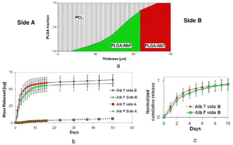
Dual-drug release from one surface of the scaffold. (a) Illustration of the compositional pattern of nanofibers. (b) Cumulative release curve of AlbF and AlbT. (c) Comparison of AlbF and AlbT release during the first 10 days.
3.4.3. Sequential Releases of Two Molecules to One Side
To achieve sequential releases of two molecules on the same side of the scaffold, the design strategy is based on the use of PCL, a hydrophobic, slowly degradable polymer, as a diffusion-barrier to segregate the molecules. Additionally, using PCL as the matrix to slow down the delivery, electrospun composite scaffolds with dual PLGA gradient patterns were designed for the sequential release of two proteins. The materials were prepared by continuous electrospinning in sequence of a 50-μm-thick layer of PCL nanofibers, a mixed layer of PCL and AlbF-loaded PLGA nanofibers with varied PCL/PLGA ratios, a 25-μm-thick transitional layer of PCL nanofibers, and a mixed layer of PCL and AlbT-loaded PLGA nanofibers with varied PCL/PLGA ratios. Figure 9a shows a schematic illustration of the pattern. The micropattern was characterized by an equal amount of AlbF-loaded PLGA and AlbT-loaded PLGA and, consequently, an equal amount of AlbF and AlbT. The overall composition was 55% (wt) of PCL, 22.5% (wt) of AlbF-loaded PLGA and 22.5% (wt) of AlbF-loaded PLGA.
Figure 9.
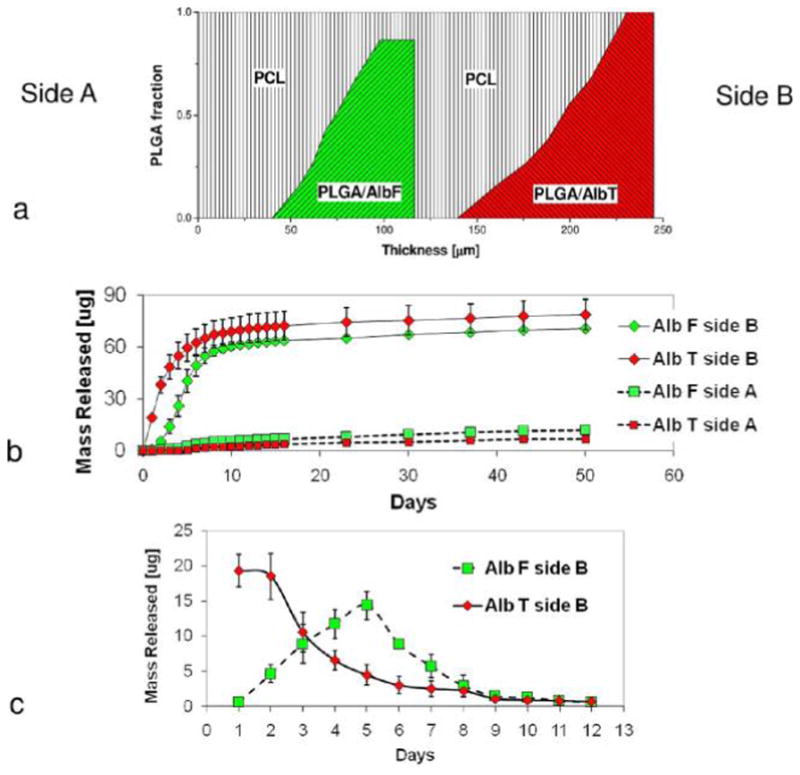
PCL-PLGA scaffold for the sequential release of proteins. (a) Illustration of the compositional pattern of nanofibers. AlbF-loaded PLGA nanofibers were confined in the middle of the scaffold, while AlbT-loaded PLGA nanofibers were close to side B. (b) Cumulative release profiles of AlbF and AlbT to both surfaces of the scaffold. (c) Net release profiles of AlbF and AlbT to side B during first 12 days.
Figure 9b showed the cumulative release profiles of AlbF and AlbT released from both sides of the scaffold. It was found that both AlbF and AlbT were delivered preferentially to Side B. The separation efficiencies of AlbF and AlbT between side B and side A were 0.92 ± 0.03 and 0.85 ± 0.04, respectively. The scaffold was highly efficient in spatially confining the delivery of both AlbT and AlbF, though the spatial confinement was more efficient for AlbT than for Alb F. AlbF was released mainly on side B, although it was originally localized in a region close to the center of the scaffold. The small difference in the PCL content on the respective side of the PLGA/AlbF nanofiber regions determined the direction of AlbF protein delivery. This result further confirmed the important role of the PCL content in segregating proteins released from molecule-impregnated PLGA fibers to achieve spatially controlled delivery. Daily net release of AlbF and AlbT to side B in the first 12 days was shown in Figure 9c. The release kinetics of AlbF and AlbT are different from the study on dual protein release above (section 3.4.2). The net release profiles of AlbT peaked on day 1 and day 2, while the net release profiles of AlbF peaked on day 5.
3.4.4. Sustained Releases of Two Molecules Respectively to the Opposite Sides
The micropattern of compositional gradient was further used as building-blocks of a more complex scaffold design for bidirectional release control purposes. As illustrated in Figure 10a, the new pattern was generated by duplicating gradient patterns on both sides symmetric with respect to PCL. Herein, PLGAac was used to encapsulate either AlbF or AlbT. The designed pattern consisted of a 25-μm-thick layer of PLGAac electrospun nanofibers loaded with different fluorophore-tagged molecules on both surfaces, a 50 μm layer of PCL nanofibers in the core of the scaffold, and two PCL-PLGAac interlayers characterized by a similar compositional gradient pattern. As a result, a precisely controlled distribution of two biomolecules was generated across the scaffold thickness. Results from molecule release showed that AlbF and AlbT were selectively released from the opposite sides of the PLGAac-PCL-PLGAac composite scaffolds. The cumulative release curves for AlbF and AlbT are shown in Figure 10b. AlbF was predominantly delivered to the reservoir on Side A, while AlbT was released to that on Side B.
Figure 10.
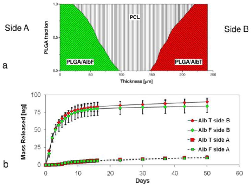
Dual-drug release from the opposite surfaces of the PLGAac-PCL-PLGAac scaffold. (a) Illustration of the compositional pattern of nanofibers. (b) Cumulative release curve of AlbT and AlbF. Release of green-emitting AlbF was mainly confined to side A, whereas release of red-emitting AlbT is mainly confined to side B.
The separation efficiency of AlbF between Side A and Side B (SAlbF_A-B) was equal to 91 ± 4%, while the separation efficiency of AlbT between Side B and Side A (SAlbT_B-A) was equal to 92 ± 3%. Therefore, the two proteins were highly confined when delivered respectively to the opposite of the scaffold.
4. DISCUSSION
This study has developed and characterized a platform of hierarchically structured electrospun biomaterial scaffolds, which use the design of tunable nanofiber micropatterns to control spatial and temporal releases of one or multiple molecules. Herein, the molecule release was illustrated by the scaffolds with micropatterns characterized by complementary density gradients of distinct nanofibers. The scaffolds consist of PLGA fibers, an “active” molecule-releasing component that impregnates and releases model molecules, and PCL fibers, a “passive” component that sequesters molecule release while provides structural and mechanical integrity. Various compositional patterns were designed and imaged with confocal microscopy which demonstrated good correlations between designed and actual patterns. Additionally, as far as we know, this study is the first that compares the use of low-molecular-weight PLGAac and PLGAes nanofibers for controlled release. The different behaviors of PLGAac and PLGAes during degradation lead to their difference in controlled molecule release in our micropatterned scaffolds. Compared to PCL-PLGAes scaffolds, PLGAac nanofibers in the PCL-PLGAac scaffolds were more stable, showing gradual and steady increase in the fiber diameter during hydrolytic degradation; and thus, the separation efficiency, a measure of spatial confinement of molecule delivery, was much higher. Thus, spatially and temporally defined releases of proteins were both accomplished with PCL-PLGAac scaffolds in this study. By taking advantage of the interplay between PCL and PLGAac, the patterned electrospun composite membranes were capable of selective release of small molecules or larger proteins on one specific side of the scaffold.
4.1. Selection of PLGA Material for Controlled Release
PLGA is a biodegradable polymer that has been used in a wide range of medical implants, tissue engineering products, and drug delivery devices, because of its slow degradation, good biocompatibility, and mechanical property.44 PLGAac and PLGAes are both widely used, but are largely different in physiochemical properties. No previous studies have examined the influence of their physiochemical properties on their nanofiber morphology alterations during degradation and their capability of encapsulating and releasing molecules. Our results suggested that the vast differences in the evolution of their nanofiber morphology could be attributed to the polymer state transition as determined from the DSC thermoanalysis. PLGAes nanofibers changed dramatically since the beginning of degradation, lost fibrous features, and turned into a dense, continuous polymeric film in a week. Conversely, PLGAac nanofibers showed delayed morphological changes to a much later stage of degradation. The rapid morphological evolution of PLGAes nanofibers can be explained by the fact that the onset point of the glass transition for PLGAes (35.2 °C) was lower than the experimental or physiological temperature (37 °C). Although the glass transition temperature of PLGAes as measured from the inflection point of the DSC curve was 38.5 °C, vast regions of PLGAes nanofibers undergo glass–rubber transitions at 37 °C. Due to the state transition, highly mobile polymer chains in the rubbery state allow polymer relaxation and water uptake. Acting as the plasticizer, the water molecules could contribute to further reduction of the glass transition temperature of PLGAes. PLGAes also underwent chemical breakdown during degradation, showing immediate reduction in molecule weight. Increased mobility of polymer chains caused nanofibers to join and then coalesce to form a continuous film. In contrast, PLGAac whose glass transition onset point was at 37.8 °C resulted in more stable nanofiber morphology. The glass–rubber transition likely was deferred, preventing water uptake. The PLGAac fibrous structure thus retained for a longer time, showing open, interconnected pores during degradation. The microstructural characteristics resulted from degradation likely contributed to the different behaviors of PCL-PLGAes and PCL-PLGAac in controlling release of molecules impregnated in the PLGA fibers. The early formation of continuous, nonporous PLGAes layer might reduce the diffusion of biomolecules toward the PLGA surface, resulting in no confined release of Rh123 from PCL-PLGAes scaffolds after day 2, whereas PCL-PLGAac scaffolds maintained sustained, spatially controlled molecule release over 6 weeks. In summary, molecule release from the nanofiber composite scaffold is largely determined by the degradation behaviors and morphological changes of PLGA fibers.
4.2. Sustained, Spatially Confined Molecule Release
Our prolonged study on the albumin release from PCL-PLGAac composite scaffolds demonstrated fast release in the first 9 days and steady but limited release over the rest of the experimental period up to 50 days. In particular, the release profile of albumin showed modest burst release (~20% of total amount) on the first day. This burst release and subsequent fast release could be attributed to (a) the nanofiber gradient pattern, as higher density of molecule-impregnated fibers were closer to the surface of the scaffold for earlier release, and (b) the molecule distribution in the nanofiber, since direct dissolution of molecules in the prespinning organic solution, as used in this study, could result in a nonuniform distribution of molecules with a large portion segregated at the nanofiber surface that are released in the aqueous medium due to desorption-related mechanisms.45,46 Different from the molecule diffusion in the initial stage, the prolonged slow release in the later stage of the assay may be attributed to the polymer degradation behavior. In addition to sustained release over the time, our release studies with small fluorophores or larger proteins, one or multiple molecules, all demonstrated high separation efficiency of molecule release on the side with higher impregnation concentration or less PCL content. Diffusion to the other side was limited to around 10%. Therefore, the compositional gradient of molecule-impregnated PLGAac nanofibers was effectively translated to sequestration of molecule release, through the use of diffusion-limiting PCL material.
4.3. Potential Applications for Regenerative Scaffolds
A new generation of scaffolding materials for tissue engineering and regenerative medicine seeks to combine the material scaffolding function such as structural guidance and mechanical support with the regenerative function such as controlled molecule release to guide cell dynamics and organization.27 Crucial to the success of in vivo and clinical studies is the potential of cells to grow healthy, functional tissues, which underlines the important role of the accurate presentation modality of signaling molecules. This study demonstrated that the use of heterogeneous nanofiber patterns in constructing scaffolding biomaterial could potentially address various signaling needs for tissue formation. Because tissue regeneration is a highly regulated process involving differentiation and spatial organization of multiple cell types in 3D, sustained release of cell-specific molecules in a spatially defined arrangement, as demonstrated here, could spatially guide cells and their commitment to regeneration. Uniform or steady presentation of a regenerative molecule may not satisfy regeneration needs in most situations,34 because overexpression of a regenerative molecule at a wrong place or a wrong time may lead to abnormal or diseased tissues. Also, biomaterials often need to interface different tissues to stimulate simultaneous regeneration of various tissue functions, which requires different molecules on opposite sides or interfaces of biomaterials.47 Though this study has demonstrated the potential of micropatterned nanofiber composite scaffolds using model fluorescent-labeled molecules or proteins, the material platform developed here can be applied to a wide range of biomedical applications, where spatial confinement and temporal control of various molecules are pivotal to the improvement of therapeutic efficacy and/or reduction of biomolecule toxicity or side effects. Our gradient pattern designs could be used as a building block to design more complex molecule-fiber structures for controlling the release kinetics and direction of multiple biomolecules. The nanofiber-based materials developed here may more readily program the desired molecule release kinetics for regeneration of mechanically strong tissues such as artery, when compared to previous studies that accomplish spatiotemporal releases for angiogenesis.48
5. CONCLUSION
We have developed and characterized micropatterned nanofiber composites made from biodegradable PCL and PLGA. This is the first demonstration of using nanofiber patterns in 3D biomaterials to achieve sustained, spatiotemporally controlled release of one or multiple proteins or small molecules. Using the graded composition and the interplay between PCL and PLGA, we showed that the hierarchically structured electrospun materials were capable of sustaining selective release of small molecules or larger proteins on one side of the scaffold. In addition, various release kinetics of combined biomolecules could be achieved by modulating the nanofiber micropattern and the composition profile including the thickness of the PCL layer, thickness, and composition of transitional layer. The hierarchically structured composite scaffolds may be used to define 3D dynamic microenvironments and likely find broader applications in tissue engineering and therapeutic device.
Supplementary Material
Acknowledgments
The research is partly funded by NIH (NHLBI 097246-01 to W.T) and State of Colorado (Biodiscovery Program to W.T.).
Footnotes
The authors declare no competing financial interest.
ASSOCIATED CONTENT
Supporting material includes Table S1 and Figures S1–S3. This material is available free of charge via the Internet at http://pubs.acs.org.
References
- 1.Pham QP, Sharma U, Mikos AG. Tissue Eng. 2006;12:1197–1211. doi: 10.1089/ten.2006.12.1197. [DOI] [PubMed] [Google Scholar]
- 2.Goldberg M, Langer R, Jia XQ. J Biomater Sci, Polym Ed. 2007;18:241–268. doi: 10.1163/156856207779996931. [DOI] [PMC free article] [PubMed] [Google Scholar]
- 3.Whatley BR, Kuo J, Shuai C, Damon BJ, Wen X. Biofabrication. 2011;3:015004. doi: 10.1088/1758-5082/3/1/015004. [DOI] [PubMed] [Google Scholar]
- 4.Baker BM, Mauck RL. Biomaterials. 2007;28:1967–77. doi: 10.1016/j.biomaterials.2007.01.004. [DOI] [PMC free article] [PubMed] [Google Scholar]
- 5.Nerurkar NL, Baker BM, Sen S, Wible EE, Elliott DM, Mauck RL. Nat Mater. 2009;8:986–92. doi: 10.1038/nmat2558. [DOI] [PMC free article] [PubMed] [Google Scholar]
- 6.Moffat KL, Wang INE, Rodeo SA, Lu HH. Clin Sports Med. 2009;28:157–76. doi: 10.1016/j.csm.2008.08.006. [DOI] [PMC free article] [PubMed] [Google Scholar]
- 7.Li WJ, Jiang YJ, Tuan RS. Tissue Eng Part A. 2008;14:639–48. doi: 10.1089/tea.2007.0136. [DOI] [PMC free article] [PubMed] [Google Scholar]
- 8.Drilling S, Gaumer J, Lannutti J. J Biomed Mater Res, Part A. 2009;88:923–34. doi: 10.1002/jbm.a.31926. [DOI] [PubMed] [Google Scholar]
- 9.Li X, Xie J, Yuan X, Xia Y. Langmuir. 2008;24:14145–50. doi: 10.1021/la802984a. [DOI] [PubMed] [Google Scholar]
- 10.Yang X, Shah JD, Wang H. Tissue Eng Part A. 2009;15:945–56. doi: 10.1089/ten.tea.2007.0280. [DOI] [PubMed] [Google Scholar]
- 11.Griffin J, Delgado-Rivera R, Meiners S, Uhrich KE. J Biomed Mater Res, Part A. 2011;97:230–42. doi: 10.1002/jbm.a.33049. [DOI] [PMC free article] [PubMed] [Google Scholar]
- 12.Slater SC, Beachley V, Hayes T, Zhang D, Welsh GI, Saleem MA, Mathieson PW, Wen X, Su B, Satchell SC. PLOS One. 2011;6:e20802. doi: 10.1371/journal.pone.0020802. [DOI] [PMC free article] [PubMed] [Google Scholar]
- 13.Dong YX, Liao S, Ngiam M, Chan CK, Ramakrishna S. Tissue Eng Part B Rev. 2009;15:333–351. doi: 10.1089/ten.TEB.2008.0619. [DOI] [PubMed] [Google Scholar]
- 14.Malafaya PB, Silva GA, Reis RL. Adv Drug Delivery Rev. 2007;59:207–233. doi: 10.1016/j.addr.2007.03.012. [DOI] [PubMed] [Google Scholar]
- 15.Karageorgiou V, Tomkins M, Fajardo R, Meinel L, Snyder B, Wade K, Chen J, Vunjak-Novakovic G, Kaplan DL. J Biomed Mater Res, Part A. 2006;78:324–34. doi: 10.1002/jbm.a.30728. [DOI] [PubMed] [Google Scholar]
- 16.Mieszawska AJ, Kaplan DL. BMC Biol. 2010;8:59. doi: 10.1186/1741-7007-8-59. [DOI] [PMC free article] [PubMed] [Google Scholar]
- 17.Zhang X, Reagan MR, Kaplan DL. Adv Drug Delivery Rev. 2009;61:988–1006. doi: 10.1016/j.addr.2009.07.005. [DOI] [PMC free article] [PubMed] [Google Scholar]
- 18.Chew SY, Wen J, Yim EK, Leong KW. Biomacromolecules. 2005;6:2017–24. doi: 10.1021/bm0501149. [DOI] [PubMed] [Google Scholar]
- 19.Cui W, Zhou Y, Chang J. Sci Tech Adv Mater. 2010;11:014108. doi: 10.1088/1468-6996/11/1/014108. [DOI] [PMC free article] [PubMed] [Google Scholar]
- 20.Bonani W, Maniglio D, Motta A, Tan W, Migliaresi C. J Biomed Mater Res, Part B. 2011;96B:276–286. doi: 10.1002/jbm.b.31763. [DOI] [PubMed] [Google Scholar]
- 21.Ionescu LC, Lee GC, Sennett BJ, Burdick JA, Mauck RL. Biomaterials. 2010;31:4113–20. doi: 10.1016/j.biomaterials.2010.01.098. [DOI] [PMC free article] [PubMed] [Google Scholar]
- 22.Wei G, Jin Q, Giannobile WV, Ma PX. J Controlled Release. 2006;112:103–10. doi: 10.1016/j.jconrel.2006.01.011. [DOI] [PMC free article] [PubMed] [Google Scholar]
- 23.Hile DD, Pishko MV. Drug Delivery. 2004;11:287–93. doi: 10.1080/10717540490493961. [DOI] [PubMed] [Google Scholar]
- 24.Guan J, Stankus JJ, Wagner WR. J Controlled Release. 2007;120:70–8. doi: 10.1016/j.jconrel.2007.04.002. [DOI] [PMC free article] [PubMed] [Google Scholar]
- 25.Nie T, Baldwin A, Yamaguchi N, Kiick KL. J Controlled Release. 2007;122:287–96. doi: 10.1016/j.jconrel.2007.04.019. [DOI] [PMC free article] [PubMed] [Google Scholar]
- 26.Sokolsky-Papkov M, Agashi K, Olaye A, Shakesheff K, Domb AJ. Adv Drug Delivery Rev. 2007;59:187–206. doi: 10.1016/j.addr.2007.04.001. [DOI] [PubMed] [Google Scholar]
- 27.Biondi M, Ungaro F, Quaglia F, Netti PA. Adv Drug Delivery Rev. 2008;60:229–242. doi: 10.1016/j.addr.2007.08.038. [DOI] [PubMed] [Google Scholar]
- 28.Discher DE, Mooney DJ, Zandstra PW. Science. 2009;324:1673–1677. doi: 10.1126/science.1171643. [DOI] [PMC free article] [PubMed] [Google Scholar]
- 29.Lee K, Silva EA, Mooney DJ. J R Soc Interface. 2011;8:153–70. doi: 10.1098/rsif.2010.0223. [DOI] [PMC free article] [PubMed] [Google Scholar]
- 30.Salvay DM, Shea LD. Mol Biosyst. 2006;2:36–48. doi: 10.1039/b514174p. [DOI] [PMC free article] [PubMed] [Google Scholar]
- 31.Chen FM, Zhang M, Wu ZF. Biomaterials. 2010;31:6279–308. doi: 10.1016/j.biomaterials.2010.04.053. [DOI] [PubMed] [Google Scholar]
- 32.Quaglia F. Int J Pharm. 2008;364:281–97. doi: 10.1016/j.ijpharm.2008.04.030. [DOI] [PubMed] [Google Scholar]
- 33.Cao L, Mooney DJ. Adv Drug Delivery Rev. 2007;59:1340–50. doi: 10.1016/j.addr.2007.08.012. [DOI] [PMC free article] [PubMed] [Google Scholar]
- 34.Silva EA, Mooney DJ. Biomaterials. 2010;31:1235–41. doi: 10.1016/j.biomaterials.2009.10.052. [DOI] [PMC free article] [PubMed] [Google Scholar]
- 35.Sy JC, Davis ME. J Cardiovasc Transl Res. 2010;3:461–8. doi: 10.1007/s12265-010-9210-x. [DOI] [PMC free article] [PubMed] [Google Scholar]
- 36.Gandhi M, Srikar R, Yarin AL, Megaridis CM, Gemeinhart RA. Mol Pharmaceutics. 2009;6:641–7. doi: 10.1021/mp800160p. [DOI] [PMC free article] [PubMed] [Google Scholar]
- 37.Ainslie KM, Lowe RD, Beaudette TT, Petty L, Bachelder EM, Desai TA. Small. 2009;5:2857–63. doi: 10.1002/smll.200901254. [DOI] [PubMed] [Google Scholar]
- 38.Sohier J, Vlugt TJH, Cabrol N, Van Blitterswijk C, de Groot K, Bezemer JM. Dual release of proteins from porous polymeric scaffolds. J Controlled Release. 2006;111:95–106. doi: 10.1016/j.jconrel.2005.11.016. [DOI] [PubMed] [Google Scholar]
- 39.Young S, Patel ZS, Kretlow JD, Murphy MB, Mountziaris PM, Baggett LS, Ueda H, Tabata Y, Jansen JA, Wong M, Mikos AG. Tissue Eng Part A. 2009;15:2347–62. doi: 10.1089/ten.tea.2008.0510. [DOI] [PMC free article] [PubMed] [Google Scholar]
- 40.Martin TA, Herman CT, Limpoco FT, Michael MC, Potts GK, Bailey RC. ACS Appl Mater Interfaces. 2011;3:3762–71. doi: 10.1021/am2009597. [DOI] [PMC free article] [PubMed] [Google Scholar]
- 41.Chakraborty S, Liao IC, Adler A, Leong KW. Adv Drug Delivery Rev. 2009;61:1043–1054. doi: 10.1016/j.addr.2009.07.013. [DOI] [PMC free article] [PubMed] [Google Scholar]
- 42.Bailey NA, Sandor M, Kreitz M, Mathiowitz E. J Appl Polym Sci. 2002;86:1868–1872. [Google Scholar]
- 43.Crescenzi V, Manzini G, Calzolari G, Borri C. Eur Polym J. 1972;8:449–463. [Google Scholar]
- 44.Puppi D, Piras AM, Detta N, Dinucci D, Chiellini F. Acta Biomater. 2010;6:1258–68. doi: 10.1016/j.actbio.2009.08.015. [DOI] [PubMed] [Google Scholar]
- 45.Zhang YZ, Wang X, Feng Y, Li J, Lim CT, Ramakrishna S. Biomacromolecules. 2006;7:1049–1057. doi: 10.1021/bm050743i. [DOI] [PubMed] [Google Scholar]
- 46.Srikar R, Yarin AL, Megaridis CM, Bazilevsky AV, Kelley E. Langmuir. 2008;24:965–74. doi: 10.1021/la702449k. [DOI] [PubMed] [Google Scholar]
- 47.Phillips JE, Burns KL, Le Doux JM, Guldberg RE, García AJ. Proc Natl Acad Sci U S A. 2008;105:12170–5. doi: 10.1073/pnas.0801988105. [DOI] [PMC free article] [PubMed] [Google Scholar]
- 48.Jain RK. Nat Med. 2003;9:685–693. doi: 10.1038/nm0603-685. [DOI] [PubMed] [Google Scholar]
Associated Data
This section collects any data citations, data availability statements, or supplementary materials included in this article.


