Abstract
The goal of this study was to investigate theoretically the effects of nonlinear propagation in a high intensity focused ultrasound (HIFU) field produced by a therapeutic phased array and the resultant heating of tissue behind a rib cage. Three configurations of focusing were simulated: in water, in water with ribs in the beam path, and in water with ribs backed by a layer of soft tissue. The Westervelt equation was used to model the nonlinear HIFU field and a 1 MHz phased array consisting of 254 circular elements was used as a boundary condition to the model. The temperature rise in tissue was modelled using the bioheat equation, and thermally necrosed volumes were calculated using the thermal dose formulation. The shapes of lesions predicted by the modelling were compared with those previously obtained in in vitro experiments at low power sonications. Intensity levels at the face of the array elements that corresponded to formation of high amplitude shock fronts in the focal region were determined as 10 W·cm−2 in the free field in water and 40 W·cm−2 in the presence of ribs. It was shown that exposures with shocks provided a substantial increase in tissue heating, and its better spatial localization in the main focal region only. The relative effects of overheating ribs and splitting of the focus due to the periodic structure of the ribs were therefore reduced. These results suggest that utilizing nonlinear propagation and shock formation effects can be beneficial for inducing confined HIFU lesions when irradiating through obstructions such as ribs. Design of compact therapeutic arrays to provide maximum power outputs with lower intensity levels at the elements is necessary to achieve shock wave regimes for clinically relevant sonication depths in tissue.
Keywords: HIFU, ultrasound surgery, ribs, nonlinear propagation, focusing, diffraction, shock heating
1. Introduction
High intensity focused ultrasound (HIFU) is an emerging medical technology capable of transcutaneous thermal ablation of target sites within a mm-sized focal region without damaging intervening tissues. While HIFU has been shown to be successful for the treatment of a range of tumors in different organs, including liver, uterus, kidney, and prostate (Wu et al 2004, Hesley et al 2008, Ritchie et al 2010, Crouzet et al 2010, Dubinsky et al 2008), a number of challenges that limit its even broader clinical application still remain. One of these challenges is related to HIFU irradiation of the liver and heart, which are partially shielded by the rib cage. The presence of ribs, which are strongly reflecting, aberrating, and absorbing obstacles for ultrasound, results in degradation of beam focusing, insufficient heating of the targeted tissue, and overheating bones and overlying tissue layers, including skin (Wu et al 2004, Civale et al 2006, Li et al 2006).
Methods which use multi-element phased arrays, the operation of whose elements is optimised to irradiate mostly through intercostal spaces and thus to minimize the ultrasound impact on the ribs, have been proposed. The principle of one group of such methods is to switch off the elements that are located in the geometrical shade of the ribs when viewed from the focal point (Botros et al 1998, Liu et al 2007, Bobkova et al 2010, Quesson et al 2010). More rigorous approaches include calculation of the optimized amplitude and phase distribution for the elements to account for diffraction effects, tissue and bone inhomogeneous structure, and scattering from ribs (Aubry et al 2008, Cochard et al 2009, Gélat et al 2011). It has been shown, both in simulation and experiment, that such optimizations provide significant reduction in heating of the ribs. However, application of the methods is not technically simple and the presence of ribs still results in degradation of focusing. For example, diffraction effects due to the regular structure of ribs can result in splitting of the focus and the appearance of the side foci, leading to an additional ~50% reduction of the intensity in the main focus, and undesired hot spots in tissue (Khokhlova et al 2010, Bobkova et al 2010).
Use of nonlinear propagation effects in exposures through obstructions such as ribs in addition to modulation of the operation of array elements, or even without such modulation, could be beneficial. Intensity levels in the focal region of HIFU beams can reach thousands of W·cm−2 (Wu et al 2004) leading to strong distortion of an acoustic waveform in the focal region. At these intensity levels, high amplitude shock fronts develop in the focus and significantly alter the in situ exposure conditions (Bailey et al 2003, Canney et al 2008). Recent experimental and modeling results give evidence that shock fronts do form in HIFU fields in tissue (Canney et al 2010). These shocks are focused into very small volumes and thus produce very effective and localized heating. Heat deposition at the focus in tissue caused by absorption at shocks of 50 – 100 MPa amplitude is several tens times higher than heating from linear focusing with the same initial intensity (Filonenko et al 2001, Canney et al 2010). The presence of shocks not only accelerates thermal ablations but also enables mechanical fractionation or emulsification of tissue using so called cavitation-cloud histotripsy (Parsons et al 2006, Maxwell et al 2011) or boiling histotripsy (Canney et al 2009, Khokhlova et al 2011) pulsing schemes. In addition, nonlinear effects accumulate on the way to the focus and are mainly present in the central focal lobe, where pressures are the highest. Nonlinear enhancement of heating therefore has a much weaker effect in the field close to the transducer, i.e. near skin and ribs, and in the additional lower amplitude side lobes in the focal region (Khokhlova et al 2011a). It was shown recently that tissue damage in the secondary lobes caused by cavitation effects in histotripsy sonication through ribs was also minimized if acoustic pressure in the main lobe exceeded the cavitation threshold and the secondary lobes remained below the threshold (Kim et al 2011). There is a promise therefore that more confined lesions can be generated using shock waves even in the absence of aberration correction at the array elements.
In order either to utilize or to avoid shock wave exposures using HIFU arrays when irradiating through ribs, it is therefore important to evaluate the degree of nonlinear effects and determine the power output levels at which shocks develop in the focus for a specific HIFU array. Numerical modelling, validated against measurement has been shown to serve as a powerful tool for characterizing nonlinear HIFU fields in water and for predicting in situ values of an acoustic field in tissue (Canney et al 2008, Bessonova et al 2009). However, to date most studies that analyze shock formation exposures have been carried out for axially symmetric single-element transducers based on the KZK equation (Filonenko et al 2001, Khokhlova et al 2002, Khokhlova et al 2006, Canney et al 2008, Bessonova et al 2009); the effect of ribs has been considered in a weakly nonlinear, and low focusing gain, field using 3D KZK modelling (Li et al 2007). When the radiator is not a single element spherical source but a multi-element 2D phased array, the modelling approach is technically much more difficult as simulation of 3D nonlinear fields with shocks requires parallel programming and large resources of computer memory. A more accurate diffraction model is also necessary to account for the wide spatial spectrum of the array field adequately. Recently, a fully 3D model based on the Westervelt equation has been developed and applied to modelling of the field of a clinical multi-element array HIFU transducer (Yuldashev and Khokhlova 2011). The results of simulations have been validated against measurements and have shown that technical parameters of the array allowed shock formation regimes in the focus in water (Kreider et al 2011). It was shown that for this particular array, shock fronts form in the focus in water at the clinically relevant intensity level of 5 W/cm2 at the array elements. The maximum intensity values for modern HIFU transducers can reach 30 – 40 W/cm2, thus leaving additional power available to compensate for absorption in tissue on the way to the focus (Cathignol 2002, Fleury et al 2002). However, the results for potential shock wave exposures are currently available for only one array and the effect of the presence of ribs has not been evaluated.
The goal of this paper was to investigate the significance of nonlinear effects in a HIFU beam generated by another typical HIFU array with and without ribs. The acoustic field of this array has been previously characterized in water at low output levels, i.e. in linear focusing regimes (Hand et al 2009). Acoustic wave propagation through a rib cage and the ability to produce thermal lesions in ex vivo porcine tissue placed behind the rib phantom has also been considered in modelling and experiment (Bobkova et al 2010). The ribs were represented as absolutely absorbing parallel strips; acoustic field modelling was based on the Rayleigh integral calculation and was limited by the linear approximation. The bioheat equation and thermal dose formulation were used to determine the size and the shape of lesions produced under these linear exposure conditions and the results of modelling were validated against experimental data (Ilyin et al 2011). Here, the 3D Westervelt model (Yuldashev and Khokhlova 2011) was generalized to simulate nonlinear propagation through ribs under the same geometrical configuration of sonications as in the previous paper (Bobkova et al 2010). Two modes of operating the array elements were compared: when all elements were switched on and when some elements were switched off to minimize the heating effect on ribs. Nonlinear modelling was first performed in water at increasing acoustic output levels, then in water in the presence of ribs on the way to focus, and finally when focusing through the ribs inside a layer of tissue. Output levels of the array at which shock fronts developed in the focus were determined. Spatial structure of the HIFU field and enhancement of tissue heating by shocks were analyzed. Various regimes of heating that utilize nonlinear effects were considered. The shapes of lesions predicted in the modelling were compared with those previously obtained in in vitro experiments at low power sonications (Bobkova et al 2010).
2. Materials and methods
2.1. Therapeutic phased array with random distribution of elements
The phased array, used in simulations, consisted of 254 circular elements, each 7 mm in diameter and 1 MHz operational frequency. The elements were distributed on a spherical surface in a quasi-random manner. The minimum centre-to-centre spacing between the elements was 7.9 mm and the largest spacing was 9.4 mm. A radius of curvature of the spherical shell and its diameter were F = 130 mm and D = 170 mm, respectively. A central hole of 40 mm diameter was provided for insertion of an imaging transducer. The active area of the array was 100 cm2. The array was developed according to the design and parameters described in the publication of Gavrilov and Hand (2000). More details about the array construction could be found in the paper of Hand et al (2009).
2.2. Numerical simulation of nonlinear acoustic field of the array
The method developed for calculation of the nonlinear acoustic field of a therapeutic phased array has been reported previously by Yuldashev and Khokhlova (2011). In the present paper it is generalized for the case when ribs and tissue are present. Simulations were performed for three configurations of the propagation medium following the methodology described below. For all configurations, pressure waveforms, distributions of intensity, peak pressures, and heat deposition rates (in the case of focusing in tissue layer) were calculated in the focal region of the beam.
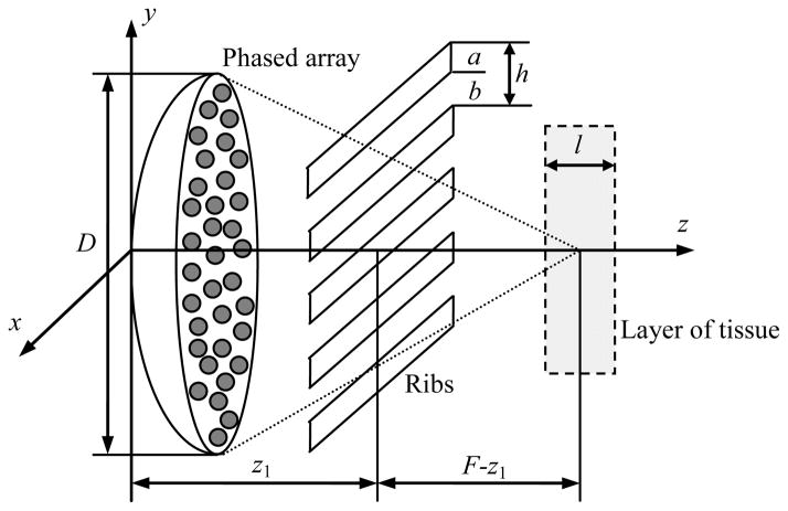
The geometry of focusing is shown in figure 1. No electronic steering of the focus was considered, and thus the focus was always located at the center of curvature of the array surface. The initial pressure distribution was first reconstructed in the initial plane z = 0 mm by applying the Rayleigh integral to the radiating elements, located at the spherical surface of the array (Yuldashev and Khokhlova 2011). This pressure distribution (figure 2a) was used as a boundary condition to the 3D Westervelt equation (Westervelt 1963). The equation was written in a retarded coordinate system to model forward propagation of acoustic waves in the direction to the focus:
| (1) |
Figure 1.
Geometry of nonlinear ultrasound field model generated by a HIFU array, and focusing through ribs into a layer of tissue.
Figure 2.
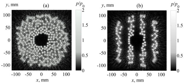
Pressure distributions reconstructed in the plane z = 0 to use as boundary conditions for nonlinear acoustic simulation of the field generated by the array. (a) –all the elements of the array are switched on. (b) –some elements of the array are switched off to minimize the ultrasonic impact on ribs. The distributions are normalized to the characteristic initial pressure amplitude p0 at the face of each element.
Here p is the acoustic pressure, z – the coordinate along the axis of the array, τ = t − z/c0, t – the time coordinate, Δ = ∂2/∂z2 + ∂2/∂y2 + ∂2/∂x2 - the Laplacian in all spatial coordinates, x and y – the transverse spatial coordinates; ρ0 – the density and c0 - the ambient sound speed in the medium, αw – coefficient of thermoviscous absorption in water, Lt – additional absorption term in tissue, β – coefficient of nonlinearity in the medium.
The linear operator Lt, which models additional absorption in tissue, governs the linear power law of absorption with frequency and the corresponding dispersion according to the equations:
| (2) |
Here c0 is the sound speed and αt 0 is the absorption coefficient at the fundamental frequency ω0 = f/f0 of ultrasound (O’Donnell et al 1981, Kashcheeva et al 2000).
Simulations were conducted using combined spectral and time domain representations of the solution for the pressure field. In the spectral domain, the pressure was represented as a Fourier series expansion using a finite number of harmonics:
| (3) |
Here pn is the pressure amplitude of the nth harmonic in the numerical solution of the equation (1), Nmax is the maximum number of harmonics included in simulations. The number Nmax was varied over the propagation distance depending on the degree of distortion of the pressure waveform. The initial number of Nmax at z = 0 was 10 and its maximum value in the focal region was 500. The transition between the spectral and temporal representations of the solution was carried out using a fast Fourier transform (FFT) from the FFTW library.
The Westervelt equation (1) was integrated over the propagation coordinate z using the method of fractional steps with a second-order operator-splitting algorithm for different physical effects: nonlinearity, diffraction, and absorption/dispersion. Two algorithms were employed to calculate the nonlinear term of the equation. In the first algorithm, a set of coupled nonlinear equations (Filonenko and Khokhlova 2001) for the amplitudes of harmonics, pn, was integrated using the Runge-Kutta method with a fourth order of accuracy (Press et al 2007). This algorithm was used in the nearfield of the beam, before formation of shocks in the pressure waveform, as it is effective for a small number of harmonics (up to several tens). At distances closer to the focus, where shock fronts developed, a conservative Godunov-type time domain scheme, which allowed accurate capture of the evolution of strongly distorted waveforms using a small number of grid points at the shocks, was used.
The diffraction term of equation (1) was calculated for each harmonic pn using the angular spectrum method (Zemp et al 2010). To reduce the reflections from the boundaries in the x and y directions, an artificial absorption quadratic with frequency, was introduced in the layer adjacent to boundaries of the spatial domain. The absorption and dispersion terms were calculated in the frequency domain using the exact solutions for each harmonic pn (Filonenko and Khokhlova 2001).
Spatial distributions of ultrasound field intensity were reconstructed from the distributions of the amplitudes of harmonics in the quasi-plane wave approximation as:
| (4) |
where |pn| is the absolute value of the complex pressure amplitude of the nth harmonic (3).
Following the approach used in the previous study (Yuldashev and Khokhlova 2011), the boundary condition to the model (1) was set at the plane z = 0 as a pressure distribution determined from the vibrations of the array elements distributed over the spherical shell. Pressure distribution was first calculated at the plane z = 2 cm using the Rayleigh integral and assuming that the elements are spherically curved circular pistons having the same magnitude V0 of the vibration velocity at their faces. Then the distribution was back projected to the plane z = 0 using the angular spectrum method. Characteristic values of the initial pressure amplitude p0 and intensity I0 were introduced as: p0 = ρ0c0V0 and .
In the first configuration, free field propagation in water was considered at increasing pressure levels I0 at the array element faces. All the elements of the array were switched on and neither ribs nor tissue were present in the acoustic beam path. Pressure fields were calculated on a 3D rectangular grid in the volume defined by 0 ≤ z ≤ 160 mm axially, x and y within the same spatial windows from −135 mm to +135 mm with spatial steps dz = λ/20 = 0.075 mm and dx = dy = λ/75 = 0.02 mm, where λ = 1.5 mm is the wavelength in water for 1 MHz frequency. Simulations were conducted for linear (β = 0 in equation 1) and nonlinear (β = 3.5) focusing for the intensity levels at the elements I0 = 1, 5, and 10 W·cm−2. Pressure waveforms calculated in each grid point of the focal region were analyzed to determine the initial intensity value I0 at which a shock front forms in the focus. The distributions of peak positive p+ and peak negative p− pressures were reconstructed along the z-axis and in the focal plane z = F from the calculated pressure waveforms. Acoustic parameters for simulations in water were chosen as: ρ0 = 1000 kg·m−3, c0 = 1500 m·s−1, β = 3.5, α0 = 4.3·10−6 m2·s−1.
In the second set of simulations, ribs were present in the beam path as shown in figure 1. Following the model of previous papers (Bobkova et al 2010, Ilyin et al 2011), the ribs were represented as infinitely thin and absolutely absorbing parallel stripes. This simplified model does not account for actual 3D shapes of the ribs that would affect overall diffraction and scattering field from the ribs. However, the condition of absolute absorption at the stripes seems to be adequate as it includes both the known strong absorption of ribs and the scattering effects in backward direction. The width of each rib was a = 18 mm, the width of the intercostal space was b = 14 mm, the plane of ribs was at z1 = 45 mm from the center of the array. Two boundary conditions were set for the modelling: when all the elements were switched on as in the previous free field simulations (figure 2a) and when the elements located opposite ribs were switched off (figure 2b), to minimize the ultrasound impact on ribs as described in the paper by Bobkova et al (2010). The corresponding boundary conditions calculated in the plane z = 0 for these two operational modes of the array are shown in the figure 2.
The distribution of the operating elements was obtained following the geometric approach: the focus was connected with the centers of each element by straight lines (rays). If the ray intersected a rib, the element was switched off; otherwise it operated with the same amplitude as without ribs. In the simulations, the intensity at the surface of each element was I0 = 1, 5, 10, 20, 30, and 40 W·cm−2. Pressure distributions in the focal region in case of the presence of ribs were calculated in two steps. At the first step, the pressure field was simulated from the plane z = 0 up to the plane z1 of the ribs. Then the pressure amplitude in the plane z1 on the ribs was set to zero. The resulting pressure distribution within the intercostal spaces was used as a boundary condition for further calculations toward the focal region. The same spatial windows and grid steps as in the free field modelling were used in simulations.
In the third set of simulations, a soft tissue layer was added to the model in the focal region of the beam as shown in figure 1. The layer of tissue was 20 mm thick and was located between the parallel planes z = 120 and 140 mm. Elements of the array were considered to be partially switched off in the same pattern as for the second case of simulations of propagation through the ribs in water only (figure 2b). This configuration corresponded to experimental conditions considered in the earlier paper (Bobkova et al 2010), where tissue heating at low output levels of sonications were investigated. Acoustic pressure field and heat deposition were calculated in tissue using the parameters ρ0 = 1000 kg·m−3, c0 = 1500 m·s−1, β = 4.7, αt0 = 4.84 m−1 (Duck 1990, Meaney et al 2000, Ilyin et al 2010). As sound speed and density in tissue were chosen the same as in water, no reflections from water/tissue interface were included in the simulations. The intensity at the elements was I0 = 2.5, 5, 10, 20, 30, and 40 W·cm−2. The lowest intensity of I0 = 2.5 W·cm−2 corresponded to the experimental conditions (Bobkova et al 2010).
2.3. Temperature and thermal dose modelling in the soft tissue behind the ribs
In order to simulate the temperature rise in tissue induced by the HIFU beam, the bioheat equation:
| (5) |
was solved. Here T is the temperature in tissue as a function of space and time, the initial temperature in tissue was T0 = 35 °C, cv = 3.06·106 J·m−3·°C−1 is the specific heat capacity per unit volume, χ = 1.93·10−7 m2·s−1 is the thermal diffusivity. Heat deposition Q in tissue was calculated from the results of nonlinear acoustic field modelling:
| (6) |
as a combination of absorption of each harmonic component of the wave.
The layer of tissue in the calculations was assumed to be thick enough that no temperature rise occurred at the outer boundary of the layer (i.e. T = T0). In the simulations of temperature (5), an explicit two-step finite-difference scheme of second order accuracy in time and space was used. The temperature distribution in tissue was calculated for a given radiated power of the array and irradiation time (exposure). The threshold for thermal damage of tissue was determined in accordance with the magnitude of thermal dose defined for the reference temperature of 56 °C (Hill et al 2004):
| (7) |
The integration was performed over the whole heating period theat (expressed in seconds), here T is the temperature (°C) of tissue, R0 = 0.5 for temperatures over 43 °C and R0 = 0.25 for temperatures less than 43 °C (Sapareto and Dewey 1984). The quantity t56 is the time equivalent of thermal dose (expressed in seconds), the value of t56 = 1 s corresponds to the threshold of destruction of tissue which is equivalent to the threshold of t43 = 140 mins (Dewey 1994, Daum and Hynynen 1998, Filonenko et al 2004). The reference temperature of 56 °C in calculating the thermal dose (7) was adopted as suggested in the book of Hill et al (2004) because this temperature and corresponding equivalent time t56 are more relevant to HIFU conditions, rather than 43 °C and t43, typical for low temperature hyperthermia conditions.
2.4. Continuous and pulse-periodic regimes of tissue heating
In order to evaluate the efficiency of nonlinear effects in tissue heating behind the ribs, two different temporal regimes of HIFU exposures were considered: continuous (cw) irradiation and pulse-periodic schemes. In both regimes, the parameters of irradiation were chosen so that the maximum temperature in tissue did not exceed 100 °C over the course of heating, because thermal effects in tissue modeled by equation (3) do not include boiling. Continuous mode was examined first and HIFU was switched on until the maximum temperature modeled in tissue reached 100°C. The results of linear and nonlinear modelling were compared. Time-to boil was determined, temperature distributions and regions of thermal lesions at the time of initiation of boiling were analyzed for different intensities at the array element faces.
The second regime was chosen as a pulse-periodic scheme, similar to those used for boiling histotripsy exposures, but assuming shorter duration of pulses so as not to reach boiling in tissue (Khokhlova et al 2011). The exposure parameters were chosen so that the time-average power of the array was the same, with an increase in the peak power within each pulse being compensated for by the pulse duration, i.e. lower duty factor (Khokhlova et al 2006). The total energy irradiated within one repetition period of pulses in the high-amplitude (nonlinear) regime was therefore the same as that in the continuous low-amplitude (linear) regime with the initial intensity I0 = 2.5 W·cm−2. The duty factor was 0.125 for an intensity of I0 = 20 W·cm−2, and 0.0625 for 40 W·cm−2. Pulse repetition time was assumed to be sufficiently short that heating could be averaged over a repetition period of the scheme. When nonlinear effects are absent, the time-average intensity is constant and thermal effects are the same for all peak intensities. When nonlinear effects become strong and shock fronts form, the enhancement of ultrasound absorption at the shocks and a more rapid increase of temperature should be observed in high pressure regions.
3. Results
3.1. Linear and nonlinear acoustic field distributions produced by the phased array in water
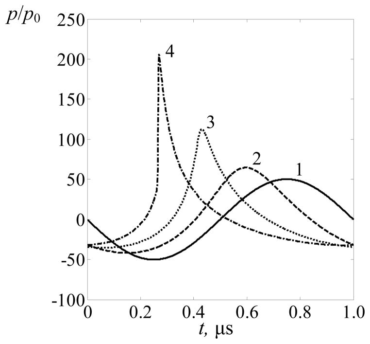
First, consider the results of the numerical simulation of the acoustic field in water. All the elements of the array were switched on, and no ribs were located on the ultrasound beam path. Figure 3 shows the comparison of focal waveforms (at z = F, x = y = 0) for the case of linear focusing (solid curve 1) and in nonlinear beams for different initial intensity values at the array elements: I0 = 1 W·cm−2 (curve 2), I0 = 5 W·cm−2 (curve 3), and I0 = 10 W·cm−2 (curve 4). The waveforms were normalized using the initial pressure at the array elements p0 = ρ0c0V0. The results showed that strong nonlinear waveform distortion and formation of a shock front are observed for the highest initial intensity of I0 = 10 W·cm−2. For initial intensities I0 below 10 W·cm−2, the waveforms exhibit nonlinear distortions with asymmetric compression and rarefaction phases, but shock fronts are not yet produced.
Figure 3.
Comparison of one cycle of the focal waveforms in a linear beam (solid curve 1) and in nonlinear beams simulated in a free field in water at I0 = 1 W·cm−2 (curve 2), I0 = 5 W·cm−2 (curve 3), and I0 = 10 W·cm−2 (curve 4), where I0 is the intensity at the array elements. All the elements of the array are switched on and no ribs are present at the beam path. The waveforms are normalized to the characteristic initial pressure amplitude p0 at the face of each element and are artificially shifted by 0.15 μs relative to each other for better separation.
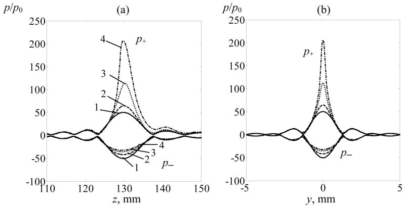
Figure 4 represents peak positive and peak negative pressure distributions along the z-axis (a) and in the focal plane (b) along the y-axis (x = 0). The distributions are normalized to the initial pressure values at the array elements. Solid curves marked (1) correspond to the linear beam simulations, dashed curves are the results of nonlinear simulations for I0 = 1 W·cm−2 (2), I0 = 5 W·cm−2 (3), and I0 = 10 W·cm−2 (4). Again, the distributions here are normalized using the initial pressure amplitude at the elements of the array. The results show that the focusing gain for the peak positive pressure in the nonlinear beam, Gp+ = p+(F)/p0, increases at higher array outputs in comparison with the linearly predicted gain G: Gp+ = 1.3G, 2.2G, and 4.1G for I0 = 1, 5, and 10 W·cm−2, respectively. The length and the width of the focal region of p+ decrease with the growth of the initial intensity from 1 W·cm−2 to 10 W·cm−2: the dimensions of the −6 dB level change from 1.6 mm to 0.5 mm along the y-axis and from 8.7 mm to 4.0 mm along the z-axis. In contrast to the peak positive pressure, the distribution of the peak negative pressure becomes longer and wider: the dimensions of the −6 dB level changes from 8.7 mm to 10.6 mm along the z-axis, and from 1.6 mm to 2 mm in the focal plane.
Figure 4.
Peak positive and peak negative pressure distributions along the z-axis (a) and in the focal plane (b) along the y-axis (x = 0). The distributions are calculated for linear beam focusing (1) and for nonlinear focusing for initial intensity at the array elements I0 = 1 W·cm−2 (2), I0 = 5 W·cm−2 (3), and I0 = 10 W·cm−2 (4). The distributions are normalized by the initial pressure amplitude p0 = ρ0c0V0.
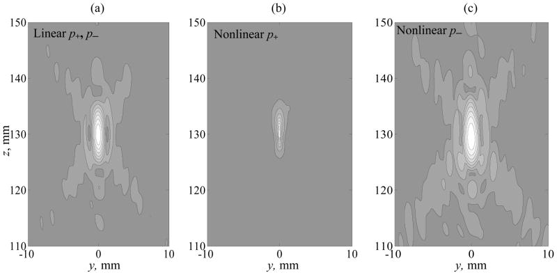
Spatial 2D distributions for the peak positive and peak negative pressures are shown in more detail in figure 5 for the linear beam (a) and strongly nonlinear case (b, c) simulated at I0 = 10 W·cm−2. In the linear beam (figure 5a), the peak positive and peak negative pressure distributions are identical. In the nonlinear case classical nonlinear-diffraction effects are observed: the peak positive distribution is much more localized in space (figure 5 b); in contrast, the distribution of the peak negative pressure is enlarged (figure 5 c) (Bessonova et al 2009). The distribution of the array elements is discrete and nonuniform, and thus some small degree of asymmetry of the field is observed along the transverse y-coordinate for lower pressure level contours. However, the focal region at the pressure levels higher than −6 dB is practically symmetric.
Figure 5.
Spatial distributions of the peak positive and peak negative pressures in an axial plane x = 0 in a linear (a) and nonlinear (b, c) field of the array. Nonlinear peak positive and peak negative pressure distributions are calculated for I0 = 10 W·cm−2. The distributions are normalized by the maximum value for each quantity. The plots contain 8 contours equally distributed from the maximum to minimum pressure levels in each plot.
Spatial 2D distributions for the peak positive and peak negative pressures are shown in more detail in figure 5 for the linear beam (a) and strongly nonlinear case (b, c) simulated at I0 = 10 W·cm−2. In the linear beam (figure 5a), the peak positive and peak negative pressure distributions are identical. In the nonlinear case classical nonlinear-diffraction effects are observed: the peak positive distribution is much more localized in space (figure 5 b); in contrast, the distribution of the peak negative pressure is enlarged (figure 5 c) (Bessonova et al 2009). The distribution of the array elements is discrete and non-uniform, and thus some small degree of asymmetry of the field is observed along the transverse y-coordinate for lower pressure level contours. However, the focal region at the pressure levels higher than −6 dB is practically symmetric.
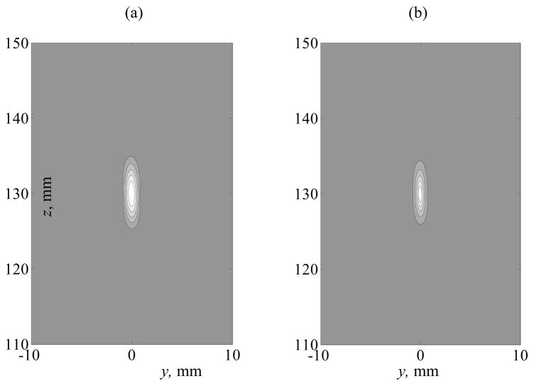
A characteristic difference in the acoustic pressure distributions in a linear and nonlinear (I0 = 10 W·cm−2) beam focusing is also noticeable in the corresponding intensity distributions shown in figure 6. Their width at the zero-zero level are practically the same in z and y-directions. At the −6 dB level the intensity beam width changes from 1.6 mm to 1.2 mm along y-axis and from 8.7 mm to 7.3 mm along z-axis.
Figure 6.
Spatial distributions of intensity in the x-plane of in a linear (a) and nonlinear (b) field of the array. The nonlinear case was calculated at I0 = 10 W·cm−2. The distributions are normalized by the maximum value for each plot. The plots contain 5 contours equally distributed from the maximum to minimum intensity level in each plot.
3.2. Effect of ribs on acoustic field distributions produced by the phased array in water
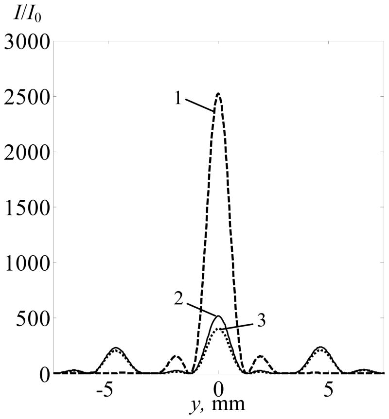
Intensity distributions in the focal plane for the case of linear focusing of the array field in the presence and absence of ribs are compared in figure 7. The distributions are normalized to the initial value of intensity I0 at the array elements. If all elements are switched on, and ultrasound propagates in water with no ribs present, the intensity distribution in the focal plane contains a single high amplitude central peak (curve 1). When ribs are present in the plane z1 = 45 mm, the intensity level in this focal peak decreases by a factor of five (curve 2). The reason for this effect is twofold. The first reason is screening of acoustic beam power by ribs. For the axial position of the rib plane considered here and their size, approximately 56% of all irradiated energy is absorbed by the ribs. The second reason is the focal splitting effect caused by the periodic structure of ribs. The splitting leads to a significant decrease of the focusing gain of the transducer as the total power in each of the side foci is about 50% of that in the main focus. The diffraction nature of this phenomenon has been discussed in detail in previous papers (Bobkova et al 2010, Khokhlova et al 2010).
Figure 7.
Intensity distributions in the focal plane along the y-axis (x = 0) transverse to the rib direction. The distributions were calculated in water for all elements switched on and no ribs present (curve 1), when all elements are switched on and ribs are in beam path (curve 2) and when ribs are present but some elements switched off to minimize the ultrasound impact on ribs (curve 3). The distributions were normalized by the element intensity I0, and ultrasound propagation was considered as linear.
If the elements of the array screened by the ribs are turned off using the simplest geometric procedure and the rest of the elements operate at the same intensity level I0, the ribs are better protected from HIFU heating. The power losses on the ribs in this case were only 25% of the total array power, i.e. more than two times less comparing to the case of all elements operating, which were 56% (Bobkova et al 2010). However, by switching these elements, additional distortions were introduced in the field distribution in the focal region (figure 7, curve 3). The intensity in the central maximum is decreased by a factor of 1.3. This means that irradiation from the elements located against the ribs provided a non-negligible contribution to the field in the central focus.
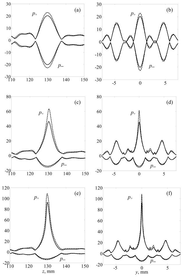
Distributions of the peak positive and peak negative pressure along the z-axis (left column) and in the focal plane along the y-axis (right column) are analyzed in figure 8. Both the cases of all array elements switched on (dashed lines), and with shadowed elements switched off (solid lines) are presented in the figure. The distributions are calculated in the presence of ribs for different intensity outputs of the array, i.e. for different degrees of nonlinear effects. The plots (a, b) correspond to linear focusing of the field. Focal splitting caused by the periodic structure of the ribs is observed in the focal plane (b) with the amplitude of the secondary maximum reaching 75% of the peak pressure value in the central focus. As the peak intensity in the central focus of the linear beam decreased by more than a factor of four in the presence of ribs (figure 7), it was expected that amplitude-dependent nonlinear effects would become significant for an initial intensity value close to I0 = 40 W·cm−2 compared to I0 = 10 W·cm−2 in the case of free field focusing in water without ribs (figure 2). The results of this case (I0 = 40 W·cm−2) and the case of moderate nonlinear effects (I0 = 20 W·cm−2) are shown in figures 8 (c–f). The asymmetry of the distributions for the peak positive and negative pressures are observed for both initial intensities, which indicates that nonlinear effects are already present, but only in the main focal lobe where the pressure is the highest. The asymmetry of the peak pressure distributions in the secondary foci is almost unnoticeable, indicating that nonlinear effects are weak in these regions. Similar to the linear focusing (a, b), both peak pressures have lower values in the main and secondary foci in the case when the array is operating with some elements switched off.
Figure 8.
Peak positive and peak negative pressure distributions along the z-axis (left column) and in the focal plane (right column) along the y-axis (x = 0) when all the elements of the array are active (dashed lines) and when some elements are switched off (solid lines). The distributions are calculated using the linear approximation (a, b) and accounting for nonlinear effects at I0 = 20 W·cm−2 (c, d) and I0 = 40 W·cm−2 (e, f). I0 is the intensity at the operating array element front face. The distributions are normalized by the initial pressure amplitude p0 = ρ0c0V0.
The degree of nonlinear effects is more obvious from analysis of the waveforms in the corresponding focal regions. The waveforms calculated in the main and secondary foci in the points (0, 0, 130 mm) and (0, 4.6 mm, 130 mm) are shown in figure 9 for the linear and two nonlinear (I0 = 20 and 40 W·cm−2) beam focusing conditions, as in the figure 8. The configuration when some elements of the array are switched off is considered. It is seen that the shock is present in the waveform in the main focus for I0 = 40 W·cm−2. At the lower source output (I0 = 20 W·cm−2), the focal waveform is distorted but not yet shocked. The waveforms in the secondary foci are only slightly distorted for both initial intensities of I0 = 20 and 40 W·cm−2.
Figure 9.
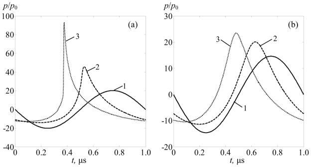
Pressure waveforms calculated in the main focus at (0, 0, 130 mm) – (a) and in the secondary focus at (0, 4.6 mm, 130 mm) – (b) for linear beam focusing (1) and accounting for nonlinear effects for I0 = 20 W·cm−2 (curves 2) and I0 = 40 W·cm−2 (curves 3). Some elements of the array are switched off to prevent rib heating. The waveforms are normalized to the initial pressure amplitude at the array elements
3.3. Nonlinear enhancement of tissue heating at the focus and suppression of side foci behind the ribs
Simulations of tissue heating behind the ribs were conducted for the array operating with some switched off elements. The ultrasound field and heat deposition rates in tissue were simulated using the linear and nonlinear acoustic models. The effect of enhanced heating due to the presence of shocks compared to linearly predicted heating was analyzed over the range of initial intensities I0 = 2.5, 5, 10, 20, 30, and 40 W·cm−2. The lowest value of I0 = 2.5 W·cm−2 was chosen, on the basis of the experimental conditions for the in vitro tissue ablation considered in previous studies (Bobkova et al 2010, Ilyin et al 2010). Higher intensity values, up to 40 W·cm−2 where nonlinear effects became significant were chosen, as shown in figure 9. For nonlinear simulations focusing gain for intensity in nonlinear beams, GI=IF/I0, increased by factors of 1.03, 1.05, 1.12, 1.3, 1.5, and 1.6 for I0 = 2.5, 5, 10, 20, 30, and 40 W·cm−2, respectively, compared to the linearly predicted GI.
The distribution of the heat deposition rates in tissue in a nonlinear beam along the z-axis (a) and in the focal plane along the y-axis (b) are shown in figure 10 for different initial intensities I0. Continuous wave (cw) irradiation is considered; each curve is normalized by the corresponding heating rate in the focus calculated using the linear approximation of ultrasound propagation. In the case of low intensity, I0 = 2.5 W·cm−2 (curves 1 and 1 ), the results of linear and nonlinear modelling are almost identical and thus the normalized peak heating rate in the main focus is equal to one. At higher intensity I0 = 20 W·cm−2 a small increase in focal heating is observed relative to the linear predictions due to nonlinear generation and absorption of higher harmonics (curve 2). A sharp change occurs between initial intensities of 20 W·cm−2 and 40 W·cm−2 when shock fronts start to develop at the focus, and the heat deposition rate increases dramatically over the linear prediction (curves 3 and 4). For initial intensity I0 = 40 W·cm−2, the heating rate calculated using the nonlinear model is 66 times higher than the heating calculated assuming linear propagation. In contrast, no enhancement of heating is observed in the secondary lobes, where pressures are lower and nonlinear effects weaker. The relative effect of heating in the secondary lobes is therefore strongly reduced in the case of nonlinear focusing through the ribs.
Figure 10.
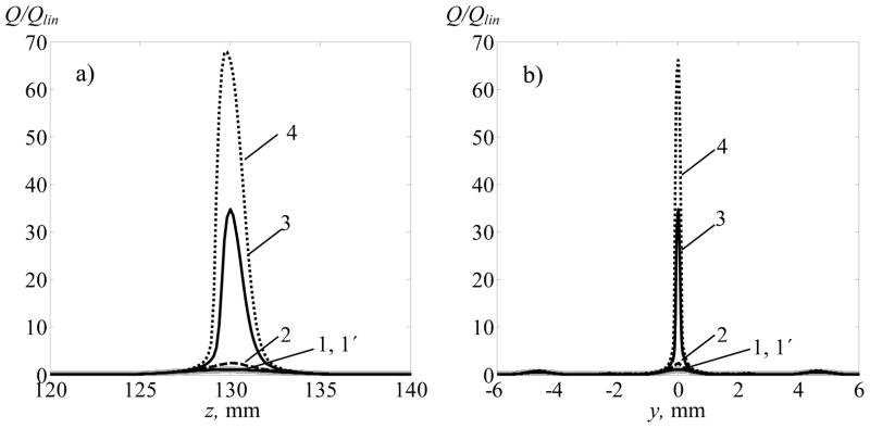
Distribution of heat deposition rate along the z-axis (a) and in the focal plane (b) along the y-axis (x = 0). The distributions were calculated using the linear approximation (grey bold curves 1) and accounting for nonlinearity for I0 = 2.5 W·cm−2 (1′), I0 = 20 W·cm−2 (2), I0 = 30 W·cm−2 (3) and I0 = 40 W·cm−2 (4).
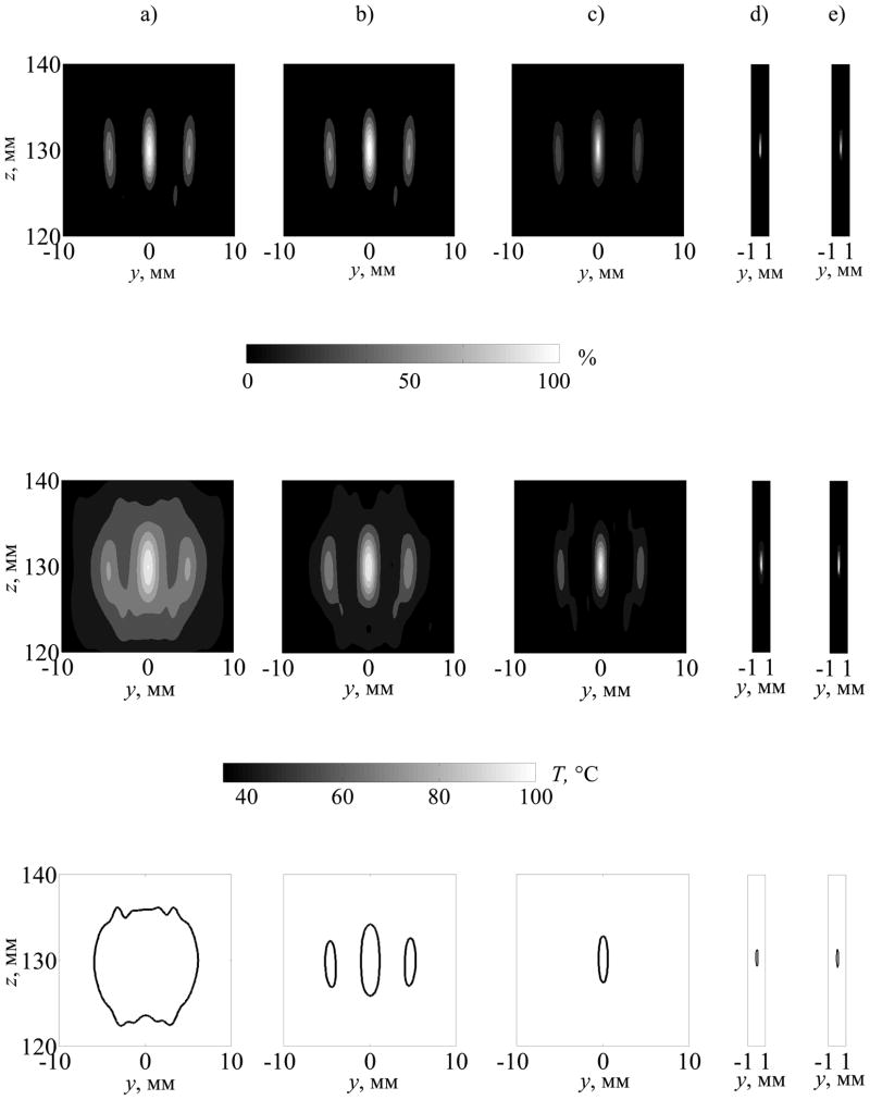
The effect of relative suppression of tissue heating in the secondary foci due to enhanced heating in the main focus is illustrated in more detail in figure 11 (upper row). Spatial distributions of heating rates in tissue are shown in the axial plane (yz) for different initial intensities at the array faces. The distributions are normalized here by the corresponding maximum value in the each plot. It is seen that with an increase of initial intensity from I0 = 2.5 W/cm2 (a) to 5 W/cm2 (b) and 20 W/cm2 (c), the heated regions in tissue become smaller and the relative level of the side foci decreases. For intensities I0 = 30 (d) and 40 W·cm−2 (e) the heating rate distributions are highly localized. The spatial window in plots (d) and (e) along the y coordinate is reduced to the region around the main focus, as the levels of the side foci are negligible.
Figure 11.
Spatial distributions of the heating rate Q/Qmax normalized to the maximum value of the corresponding distributions (upper row), temperature distributions T°C (middle row), and contours of thermal lesions in tissue (bottom row) at the time when the temperature in the center of the main focus reaches 100°C. Initial intensity at the array element front faces is: I0 = 2.5 W/cm2 (a), 5 W/cm2 (b), 20 W/cm2 (c), 30 W/cm2 (d), 40 W/cm2 (e).
Temperature distributions in tissue for the same values of initial intensity I0, and for nonlinear simulations, are presented in the middle row of figure 11 for the moment when peak temperature in tissue reaches 100°C. This temperature was reached in t = 19 s for I0 = 2.5 W·cm−2; t = 3.2 s (I0 = 5 W·cm−2); 740 ms (I0 = 10 W·cm−2); 190 ms (I0 = 20 W·cm−2); 9.5 ms (I0 = 30 W·cm−2); and 2.5 ms (I0 = 40 W·cm−2). The thermal dose is calculated at the same times and corresponding contours of thermal lesions are shown in the bottom row of the figure. Again, continuous wave exposures with switched subset of elements are considered.
For the lowest intensity and longest heating (I0 = 2.5 W·cm−2, t = 19 s), the main and two side heated regions merge due to heat diffusion and form one expanded lesion. This effect has also been observed in the experiments of the earlier study (Bobkova et al 2010) at the intensity output of the array shown in figure 12. In this case, the results of linear and nonlinear simulations are very close: for the linear (black curves) and nonlinear models (white curves) of heating the lesions are identical and show good agreement with the experiment (white colour in the images of tissue). Focal splitting is clearly observed in figure 11 in the temperature distributions for lesions formed for higher intensity and shorter heating times (I0 = 5 W·cm−2, 3.2 s). With further increase of intensity and decrease in heating time (I0 = 20, 30, and 40 W·cm−2) the dimensions of the central lesion in the main focus become smaller and the side foci disappear. These results show that by using nonlinear effects, it is possible to heat very localized tissue volumes up to boiling temperatures within very short exposure times, and to reduce the relative level of heating in undesired hot spots that form in the case of the linear beam propagation through the ribs.
Figure 12.
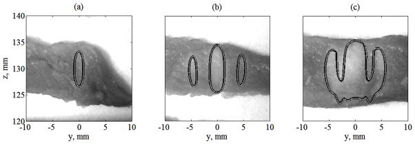
Contours of lesions modeled in the axial plane (x = 0) super-imposed on the images of lesions produced in ex vivo tissue samples. The contours were calculated using linear (dark curves) and nonlinear (thin white curves) acoustic modelling at I0 = 2.5 W·cm−2 after 5 s (a), 10 s (b) and 15 s (c) of heating.
The results of modelling acoustic and temperature fields in tissue are summarized in Table 1.
Table 1.
HIFU field parameters in a soft layer placed in the focal region behind the ribs. The array elements located in the shadow of ribs were switched off.
| Initial intensity I0, W·cm−2 | 2.5* | 2.5 | 5 | 10 | 20 | 30 | 40 |
| Initial pressure p0, MPa | 0.27 | 0.27 | 0.39 | 0.55 | 0.77 | 0.95 | 1.1 |
| Focusing gain, GI = IF/I0 | 367 | 377 | 387 | 410 | 476 | 552 | 580 |
| Ratio of intensities in the main and side foci Imain/Iside | 1.90 | 1.94 | 1.99 | 2.09 | 2.39 | 2.75 | 2.86 |
| Focusing gain, Gp = pF/p0 | 19.2 | 23.5 | 26.2 | 31.8 | 50.9 | 77.1 | 80.8 |
| Ratio of pressures in the main and side foci pmain/pside | 1.4 | 1.5 | 1.6 | 1.8 | 2.5 | 3.5 | 3.3 |
| Ratio of linear and nonlinear heating rates in the main focus QN/QL | 1.00 | 1.07 | 1.15 | 1.37 | 2.39 | 34.8 | 66.2 |
| Ratio of heating rates in the main and side foci Qmain/Qside | 1.90 | 2.00 | 2.12 | 2.42 | 3.92 | 45.4 | 71.3 |
| Time of achieving 100°C in the main focus, ms | 19100 | 19000 | 3200 | 740 | 190 | 9.5 | 2.5 |
| Ratio of temperature rise in the main and side foci when temperature in the main focus reaches 100 °C, ΔTmain/ΔTside | 1.79 | 1.82 | 2.00 | 2.20 | 3.00 | 26.0 | 65.0 |
The second column, marked as 2.5*W/cm2 for the initial intensity, corresponds to linear acoustic modelling, other initial values correspond to nonlinear modelling.
The previous figures have illustrated nonlinear enhancement of tissue heating in the main focus, relative suppression of the side foci, and reducing time to reach boiling temperatures for continuous wave (cw) exposures. Recent studies have shown a growing interest in using pulse-periodic schemes that enable combined thermal and mechanical bioeffects in tissue when high peak intensities are used within pulses and thus nonlinear effects are present (Parsons et al 2006, Khokhlova et al 2011). When irradiating through ribs, the use of such schemes (concentrating acoustic power in a shorter pulse within a longer repetition period) provides additional benefits compared to continuous exposures with the same time-average power. While increasing the peak power in the pulse results in significant nonlinear enhancement of heating in the focus, the ultrasound field in the rib plane is almost linear, and therefore no extra heating of ribs occurs. This situation is illustrated in figure 13 where the temperature rise over time in the main, and one of the side, foci is presented for pulse-periodic irradiation regime with different peak intensity values I0 and different pulse durations. The total energy irradiated within one pulse repetition period in the high-amplitude pulsing (nonlinear) regimes corresponds to the energy of continuous irradiation with an initial intensity I0 = 2.5 W·cm−2 (linear). The duty factor for intensity 20 W·cm−2 is 0.125, and for 40 W·cm−2 - 0.0625. At lower peak intensity levels I0 ≤ 20 W·cm−2, when no shocks are present in the focal waveform, almost no difference is observed in the temperature curves in either the main or the secondary foci. With intensities of I0 = 30 and 40 W·cm−2, shocks form in the main focus, leading to significant acceleration of the temperature rise in this position, and no increase in heating occurs in the secondary focus. With the same time-average intensity, tissue ablation in the focus is reached in less than 15 ms at 40 W·cm−2 and 80 ms at 30 W·cm−2 compared to 2 s for continuous exposure at 2.5 W·cm−2.
Figure 13.
Temperature in the main focus (a) and in one of the split foci (b) against irradiation time for the same time-average, and different peak, intensities I0 at the array elements: I0 = 2.5 W·cm−2 in continuous mode (1) and I0 = 10 W·cm−2 (2), I0 = 20 W·cm−2 (3), I0 = 30 W·cm−2 (4) and I0 = 40 W·cm−2 (5) in the pulse-periodic regimes. Curves 1–5 were simulated accounting for nonlinear effects, curve 1 was simulated linearly for I0 = 2.5 W·cm−2.
4. Discussion
Efficient tissue heating by shock waves have been shown to have some advantages in enhancing thermal effects in HIFU as well as in producing mechanical tissue disruption (Canney et al 2009, Khokhlova et al 2011). However, no studies have yet been done to evaluate the effects of shocks in tissue when using 2D multi-element HIFU arrays, and in the clinically important situation of sonicating through ribs. In this paper, nonlinear effects were studied in a high intensity focused ultrasound (HIFU) field produced by a typical therapeutic phased array in a free field in water, in water in the presence of ribs, and in a tissue layer behind the ribs. An array of 1 MHz frequency, 170 mm diameter, 130 mm focal length, consisting of 254-elements (focusing gain for pressure amplitude at low power output in water is Gp = pF/p0 = 48) was considered (Hand et al 2009, Bobkova et al 2010). Nonlinear enhancement of tissue heating in the central focus, corresponding relative suppression of side foci caused by diffraction due to the periodic structure of ribs, and different continuous wave and pulse-periodic regimes of tissue heating were evaluated.
The results of numerical modelling showed that when nonlinear propagation effects were sufficiently strong to create shock fronts in the pressure waveforms in the focus in water, the peak positive pressure in the waveform was 100 MPa, peak negative pressure - 15 MPa, and shock front amplitude - 90 MPa (figure 3, curve 4). The initial intensity at the array elements in this case was 10 W·cm−2 (0.55 MPa initial pressure). When irradiating through ribs, similar parameters were observed in the focal waveform at four times greater initial intensity of 40 W·cm−2 (1.1 MPa pressure). As shown in figure 10, in the case of focusing in tissue in the presence of ribs at an initial intensity of 40 W·cm−2 nonlinear heating of tissue is about 70 times greater than for the case of linear propagation at the same initial intensity. This strong enhancement of heating can potentially be used to accelerate purely thermal ablation of tissue by fast steering of the focus over the heated volume, as well as to realize newer protocols of mechanical tissue emulsification based on rapid shock wave heating - boiling histotripsy (Canney et al 2009, Khokhlova et al 2011). With an initial intensity of I0 = 40 W·cm−2, boiling in tissue was reached after 2.5 ms of irradiation, which is about four orders of magnitude faster than for low output sonications: 19 s for I0 = 2.5 W·cm−2. In addition to acceleration of tissue ablation, shorter shock wave exposures in in vivo clinical conditions (not considered here) would also reduce the effect of blood perfusion thus leading to more predictable outcomes of the treatment.
An important advantage of using shock wave exposures while irradiating through ribs has been revealed in this study. It has been shown that at higher intensities the relative effect of heating tissue in additional side foci formed due to diffraction by the periodic structure of ribs is reduced significantly (figure 11). Nonlinear effects are amplitude dependent; they also accumulate with propagation distance through high pressure regions. When the initial intensity at the array is sufficiently high that shocks form within the region of the main focus, nonlinear waveform distortion is almost negligible in the side foci of lower amplitude (figure 9). The relative effect of overheating unwanted tissue volumes is therefore reduced significantly. When modelling thermal effects at 1 cm depth of focus in tissue, strong nonlinear effects in terms of localized enhancement of heating in the main focal lobe and relative suppression of side heated spots were observed for initial intensities higher than 30 W·cm−2. Although these effects are illustrated here for the side lobes formed due to diffraction by the regular structure of ribs, the same mechanism can be applied to other unwanted secondary hot spots in tissue, formed, for example, due to tissue inhomogeneities or electronic steering of the array focus. Extra nonlinear heating by shocks will occur in the region of the main focus only, thus the relative thermal effect in other hot spots will be suppressed. This idea shows the potential for developing nonlinear HIFU irradiation protocols to produce confined lesions while better protecting overlying tissues, and ribs. As noted earlier in the introduction, a similar effect, but related to the value of the peak negative pressure was recently observed for cavitation-cloud histotripsy lesions as long as the pressure in the main lobe exceeds the cavitation cloud initiation threshold and secondary lobes remain below the threshold (Kim et al 2011).
Moreover, since heating is enhanced in the main focus only, and not at the ribs where the field is almost linear, even sonications carried out without switching off the array elements may be applicable. Pulse-periodic schemes with high peak intensities and low duty factors, as illustrated in figure 13, can be used to create lesions in the focus while not overheating ribs. Similarly, the paper by Kim et al (2011) proposes that histotripsy can generate confined focal lesions through rib obstacles without aberration correction at the array because the threshold for cavitation cloud formation, which is the mechanism for tissue damage, is not exceeded close to ribs. In addition to optimizing the array design, in some cases, when mechanical movement of the transducer instead of electronic steering of the array focus is acceptable, an array can be substituted by a single element source to use the total area of its surface for radiation and thus reach higher pressures in the focus necessary for shock formation.
The initial intensity values of 30 – 40 W·cm−2 reported here to reach shocks with this specific array are about the maximum that current transducers can provide while ensuring their safety in terms of thermal or mechanical damage (Cathignol 2002, Fleury et al 2002). In the case of focusing deeper into tissue than in the current study, higher values of initial intensity will be needed to compensate for additional absorption to reach the same pressures at the focus. However, variation of the array parameters (frequency, sparseness, focal length, and aperture) can decrease the threshold value of the array intensity required to produce shocks in the focus. For example, shock fronts form in the focus at half the initial intensity levels, at 5 W·cm−2 for another typical HIFU array, operating at a slightly higher frequency (1.2 MHz against 1 MHz) and with more compact distribution of the elements (64% against 40% area of the shell filled by the elements) (Yuldashev and Khokhlova 2011). Current trend is also to develop HIFU arrays with larger number of elements (Marsac et al 2012) and more compact distribution (Raju et al 2011) which will lead to the same pressures at the focus for lower initial intensities. The potential to reach and utilize shock wave exposures in tissue using 2D arrays even in the presence of ribs is therefore realistic.
The Westervelt-type equation extended for linear frequency law of absorption in tissue was shown to provide a useful model to evaluate nonlinear propagation effects in ultrasound fields generated by 2D HIFU arrays. Although the modelling is currently implemented to simulate forward ultrasound propagation only, i.e. does not account for the reflected waves, it still adequately captures the major bioeffects in tissue in the focal region. Nonlinear simulations, including the formation of shocks, have been validated against measurements in water for another 2D HIFU array with similar parameters (Kreider et al 2011) and shown good agreement. An acoustic model was combined here with the bioheat equation to model temperature rise in tissue, and thermally necrosed volumes were calculated based on the thermal dose formulation. The shapes of lesions predicted in the modelling showed good agreement with those previously obtained in in-vitro experiments at low power sonications. Previous studies of shock wave irradiation in simpler fields of single-element transducers using a KZK model in the absence of ribs have shown good correlation between heating by shocks and predicted bioeffects in simulation and experiment. Further studies are planned to design and build a multi-element HIFU array to implement shock wave heating regimes experimentally in tissue, as well as to evaluate the ability of using single-element transducers without overheating ribs.
5. Conclusion
Numerical simulations based on the nonlinear Westervelt-type equation have shown that high amplitude shock fronts can form at the focus of a multi-element focused therapeutic array at technically feasible intensity levels at the array elements while sonicating through ribs. Formation of shocks results in significant enhancement of tissue heating only in the main focus and the enhancement of heating was negligible in the side lobes of the field and at the ribs, where nonlinear effects are weak. Pulse-periodic exposures with high peak intensities and low duty cycle can be used to enhance thermal effects at the focus. As the total HIFU-on time to create a lesion using shock waves is significantly shorter, better protection of ribs can be provided even without additional aberration correction by adjustment of the operating parameters of the array elements. These results suggest that utilizing shocks can be beneficial to enable rapid generation of precise and localized lesions in tissue while better protecting ribs and overlaying tissues. Additional optimization of parameters and the design of compact therapeutic arrays to provide maximum power outputs with lower intensity levels at its elements is necessary to achieve shock wave regimes for sonications deep in tissue.
Acknowledgments
This work was supported in part by the National Institute of Health (project no EB007643) and the Russian Foundation for Basic Research (projects no 12-02-00028 and 12-02-31388). Numerical simulations were performed on the SKIF “Chebyshev” and the “Lomonosov” clusters of MSU supercomputer center. The authors gratefully acknowledge A Shaw and J Hand for the help in getting experimental data for comparison with modelling and unfunded partnership with the European Metrology Research Programme (project no HLT03). We are especially thankful to G ter Haar for the editorial comments and fruitful discussions.
References
- Aubry J-F, Pernot M, Marquet F, Tanter M, Fink M. Transcostal high-intensity-focused ultrasound: ex vivo adaptive focusing feasibility study. Phys Med Biol. 2008;53:2937–51. doi: 10.1088/0031-9155/53/11/012. [DOI] [PMC free article] [PubMed] [Google Scholar]
- Bailey MR, Khokhlova VA, Sapozhnikov OA, Kargl SG, Crum LA. Physical mechanisms of the therapeutic effect of ultrasound. Acoust Phys. 2003;49(4):369–88. [Google Scholar]
- Bessonova OV, Khokhlova VA, Bailey MR, Canney MS, Crum LA. Focusing of high power ultrasound beams and limiting values of shock wave parameters. Acoust Phys. 2009;55(4–5):463–73. doi: 10.1134/S1063771009040034. [DOI] [PMC free article] [PubMed] [Google Scholar]
- Bessonova OV, Khokhlova VA, Canney MS, Bailey MR, Crum LA. A derating method for therapeutic applications of high intensity focused ultrasound. Acoust Phys. 2010;56(3):376–85. doi: 10.1134/s1063771010030140. [DOI] [PMC free article] [PubMed] [Google Scholar]
- Bobkova S, Gavrilov L, Khokhlova V, Shaw A, Hand J. Focusing of high intensity ultrasound through the rib cage using therapeutic random phased array. Ultrasound Med Biol. 2010;36:888–906. doi: 10.1016/j.ultrasmedbio.2010.03.007. [DOI] [PMC free article] [PubMed] [Google Scholar]
- Botros YY, Ebbini ES, Volakis JL. Two-step hybrid virtual array-ray (VAR) technique for focusing through the rib cage. IEEE Trans Ultrasound Ferroelectr Freq Control. 1998;45(4):989–99. doi: 10.1109/58.710577. [DOI] [PubMed] [Google Scholar]
- Canney MS, Bailey MR, Crum LA, Khokhlova VA, Sapozhnikov OA. Acoustic characterization of high intensity focused ultrasound fields: A combined measurement and modeling approach. J Acoust Soc Am. 2008;124(4):2406–20. doi: 10.1121/1.2967836. [DOI] [PMC free article] [PubMed] [Google Scholar]
- Canney M, Khokhlova V, Hwang JH, Khokhlova T, Bailey M, Crum L. Tissue erosion using shock wave heating and millisecond boiling in high intensity ultrasound field. Proc. 9th International Symposium on Therapeutic Ultrasound; 23–26 September. 2009; Aix-En-Provence, France. 2009. pp. 36–9. [Google Scholar]
- Canney M, Khokhlova V, Bessonova O, Bailey M, Crum L. Shock-induced heating and millisecond boiling in gels and tissue due to high intensity focused ultrasound. Ultrasound Med Biol. 2010;36:250–67. doi: 10.1016/j.ultrasmedbio.2009.09.010. [DOI] [PMC free article] [PubMed] [Google Scholar]
- Cathignol D. High intensity piezoelectric sources for medical applications: technical aspects. In: Rudenko OV, Sapozhnikov OA, editors. Nonlinear Acoustics at the Beginning of the 21st Century; Proc. of 16th ISNA; Moscow. 2002. p. 371. [Google Scholar]
- Civale J, Clarke R, Rivens Iter Haar G. The use of a segmented transducer for rib sparing in HIFU treatments. Ultrasound Med Biol. 2006;32:1753–61. doi: 10.1016/j.ultrasmedbio.2006.06.005. [DOI] [PubMed] [Google Scholar]
- Cochard E, Prada C, Aubry JF, Fink M. Ultrasonic focusing through the ribs using the DORT method. Med Physics. 2009;36(8):3495–503. doi: 10.1118/1.3159755. [DOI] [PubMed] [Google Scholar]
- Crouzet S, Murat FJ, Pasticier G, Cassier P, Chapelon JY, Gelet A. High intensity focused ultrasound (HIFU) for prostate cancer: current clinical status, outcomes and future perspectives. Int J Hyperthermia. 2010;26(8):796–803. doi: 10.3109/02656736.2010.498803. [DOI] [PubMed] [Google Scholar]
- Daum DR, Hynynen K. Thermal dose optimization via temporal switching in ultrasound surgery. IEEE Trans Ultrasound Ferroelectr Freq Control. 1998;45:208–15. doi: 10.1109/58.646926. [DOI] [PubMed] [Google Scholar]
- Dewey WC. Arrhenius relationships from the molecule and cell to the clinic. Int J Hyperthermia. 1994;10:457–83. doi: 10.3109/02656739409009351. [DOI] [PubMed] [Google Scholar]
- Dubinsky TJ, Cuevas C, Dighe MK, Kolokythas O, Hwang JH. High-intensity focused ultrasound: current potential and oncologic applications. AJR Am J Roentgenol. 2008;190:191–9. doi: 10.2214/AJR.07.2671. [DOI] [PubMed] [Google Scholar]
- Duck FA. Physical Properties of Tissue. London: Academic Press Inc; 1990. p. 346. [Google Scholar]
- Filonenko EA, Khokhlova VA. Effect of acoustic nonlinearity on heating of biological tissue induced by high intensity focused ultrasound. Acoust Phys. 2001;47(4):468–75. [Google Scholar]
- Filonenko EA, Gavrilov LR, Khokhlova VA, Hand JW. Heating of biological tissues by two-dimensional phased arrays with random and regular element distributions. Acoust Phys. 2004;50:222–31. [Google Scholar]
- Fleury G, Berriet R, Le Baron O, Huguenin B. New piezocomposite transducers for therapeutic ultrasound. 2nd Int. Symp. on Therapeutic Ultrasound; Seattle. 2002. [Google Scholar]
- Gavrilov LR, Hand JW. A theoretical assessment of the relative performance of spherical phased arrays for ultrasound surgery. IEEE Trans Ultrason Ferroelectr Freq Control. 2000;47:125–39. doi: 10.1109/58.818755. [DOI] [PubMed] [Google Scholar]
- Gélat P, ter Haar G, Saffari N. Modelling of the acoustic field of a multi-element HIFU array scattered by human ribs. Phys Med Biol. 2011;56:5553–81. doi: 10.1088/0031-9155/56/17/007. [DOI] [PubMed] [Google Scholar]
- Hand JW, Shaw A, Sadhoo N, Dickinson RJ, Gavrilov LR. Initial testing of a prototype phased array device for delivery of High Intensity Focused Ultrasound (HIFU) Phys Med Biol. 2009;54:5675–93. doi: 10.1088/0031-9155/54/19/002. [DOI] [PubMed] [Google Scholar]
- Hesley GK, Gorny KR, Henrichsen TL, Woodrum DA, Brown DL. A clinical review of focused ultrasound ablation with magnetic resonance guidance: an option for treating uterine fibroids. Ultrasound Quarterly. 2008;24(2):131–9. doi: 10.1097/RUQ.0b013e31817c5e0c. [DOI] [PubMed] [Google Scholar]
- Hill CR, Bamber JC, ter Haar G, editors. Physical Principles of Medical Ultrasonics. 2. West Sussex, UK: John Wiley & Sons; 2004. [Google Scholar]
- Ilyin SA, Bobkova SM, Khokhlova VA, Gavrilov LR. Simulation of thermal lesions in biological tissues irradiated by high-intensity focused ultrasound through the rib cage. Physics of Wave Phenomena. 2011;19(1):62–7. [Google Scholar]
- Kashcheeva SS, Sapozhnikov OA, Khokhlova VA, Averkiou MA, Crum LA. Nonlinear distortion and attenuation of intense acoustic waves in lossy media obeying a frequency power law. Acoustical Physics. 2000;46(2):170–7. [Google Scholar]
- Khokhlova VA, Souchon R, Tavakkoli J, Sapozhnikov OA, Cathignol D. Numerical modeling of finite-amplitude sound beams: Shock formation in the near field of a cw plane piston source. J Acoust Soc Am. 2002;110(1):95–108. [Google Scholar]
- Khokhlova VA, Bailey MR, Reed JA, Cunitz BW, Kaczkowski PJ, Crum LA. Effects of nonlinear propagation, cavitation, and boiling in lesion formation by high intensity focused ultrasound in a gel phantom. J Acoust Soc Am. 2006;119(3):1834–48. doi: 10.1121/1.2161440. [DOI] [PubMed] [Google Scholar]
- Khokhlova TD, Canney MS, Khokhlova VA, Sapozhnikov OA, Crum LA, Bailey MR. Controlled tissue emulsification produced by high intensity focused ultrasound shock waves and millisecond boiling. J Acoust Soc Am. 2011;130(5):3498–510. doi: 10.1121/1.3626152. [DOI] [PMC free article] [PubMed] [Google Scholar]
- Khokhlova VA, Bobkova SM, Gavrilov LR. Focus splitting associated with propagation of focused ultrasound through the rib cage. Acoust Phys. 2010;56(5):665–74. doi: 10.1134/S106377101005012X. [DOI] [PMC free article] [PubMed] [Google Scholar]
- Khokhlova VA, Yuldashev PV, Bobkova SM, Ilyin SA. The role of nonlinear propagation effects in ablation of soft tissue behind the rib cage using a HIFU phased array. Proc. 11th Int. Symp. on Therapeutic Ultrasound; New York. 2011a. p. 52. [Google Scholar]
- Kim Y, Wang T-Y, Zhen Xu, Cain CA. Lesion generation through ribs using histotripsy therapy without aberration correction. IEEE Trans Ultrason Ferroelectr Freq Control. 2011;58(11):2334–43. doi: 10.1109/TUFFC.2011.2091. [DOI] [PMC free article] [PubMed] [Google Scholar]
- Kreider W, Sapozhnikov OA, Farr N, Yuldashev PV, Partanen A, Brazzle D, Bailey MR, Kaczkowski PJ, Khokhlova VA. Acoustic holography and nonlinear modeling methods to characterize the Philips MR-guided HIFU source. Proc. 11th Int. Symp. on Therapeutic Ultrasound; New York. 2011. p. 41. [Google Scholar]
- Li F, Gong X, Hu K, Li C, Wang Z. Effect of ribs in HIFU beam path on formation of coagulative necrosis in goat liver. Proc. 5th Int. Symp. on Therapeutic Ultrasound; Boston. 2006. pp. 477–80. [Google Scholar]
- Li J-L, Liu X-Z, Zhang D, Gong X-F. Influence of ribs on the nonlinear sound field of therapeutic ultrasound. Ultrasound Med Biol. 2007;33:1413–20. doi: 10.1016/j.ultrasmedbio.2007.05.001. [DOI] [PubMed] [Google Scholar]
- Liu H-Li, et al. Feasibility of transrib focused ultrasound thermal ablation for liver tumors using a spherically curved 2D array: A numerical study. Med Phys. 2007;34(9):3436–48. doi: 10.1118/1.2759888. [DOI] [PubMed] [Google Scholar]
- Marsac L, Chauvet D, Larrat B, Pernot M, Robert B, Fink M, Boch AL, Aubry JF, Tanter M. MR-guided adaptive focusing of therapeutic ultrasound beams in the human head. Med Phys. 2012;39(2):1141–9. doi: 10.1118/1.3678988. [DOI] [PMC free article] [PubMed] [Google Scholar]
- Maxwell AD, Wang T-Y, Cain CA, Fowlkes JB, Sapozhnikov OA, Bailey MR, Xu Z. Cavitation clouds created by shock scattering from bubbles during histotripsy. J Acoust Soc Am. 2011;130:1888–98. doi: 10.1121/1.3625239. [DOI] [PMC free article] [PubMed] [Google Scholar]
- Meaney PM, Cahill MD, ter Haar GR. The intensity dependence of lesion position shift during focused ultrasound surgery. Ultrasound Med Biol. 2000;26:441–50. doi: 10.1016/s0301-5629(99)00161-1. [DOI] [PubMed] [Google Scholar]
- O’Donnell M, Janes ET, Miller JG. Kramers-Kronig relationship between ultrasonic attenuation and phase velocity. J Acoust Soc Am. 1981;69:696–701. [Google Scholar]
- Parsons J, Cain C, Abrams G, Fowlkes J. Pulsed cavitational ultrasound therapy for controlled tissue homogenization. Ultrasound Med Biol. 2006;32:115–29. doi: 10.1016/j.ultrasmedbio.2005.09.005. [DOI] [PubMed] [Google Scholar]
- Press WH, Teukolsky SA, Vetterling WT, Flannery BP. Numerical Recipes in FORTRAN. 2. Vol. 77. Cambridge University Press; New York: 2007. [Google Scholar]
- Quesson B, Merle M, Kohler MO, Mougenot C, Roujol S, de Senneville BD, Moonen CT. A method for MRI guidance of intercostal high intensity focused ultrasound ablation in the liver. Med Phys. 2010;37(6):2533–40. doi: 10.1118/1.3413996. [DOI] [PubMed] [Google Scholar]
- Raju BI, Hall CS, Seip R. Ultrasound therapy transducers with space-filling non-periodic arrays. IEEE Trans Ultrason Ferroelectr Freq Control. 2011;58:944–54. doi: 10.1109/TUFFC.2011.1895. [DOI] [PubMed] [Google Scholar]
- Ritchie RW, Leslie T, Phillips R, Wu F, Illing R, ter Haar G, Protheroe A, Cranston D. Extracorporeal high intensity focused ultrasound for renal tumours: a 3-year follow-up. British Journal Urology International. 2010;106(7):1004–9. doi: 10.1111/j.1464-410X.2010.09289.x. [DOI] [PubMed] [Google Scholar]
- Sapareto SA, Dewey WC. Thermal dose determination in cancer therapy. Int J Radiat Oncol Biol Phys. 1984;10:787–800. doi: 10.1016/0360-3016(84)90379-1. [DOI] [PubMed] [Google Scholar]
- Westervelt PJ. Parametric acoustic array. J Acoust Soc Am. 1963;35(4):535–7. [Google Scholar]
- Wu F, Zhi-Biao W, Wen-Zhi C, Hui Z, Jin B, Jian-Zhong Z, Ke-Quan L, Cheng-Bing J, Fang-Lin X, Hai-Bing S. Extracorporeal high intensity focused ultrasound ablation in the treatment of patients with large hepatocellular carcinoma. Ann Surg Oncol. 2004;11:1061–9. doi: 10.1245/ASO.2004.02.026. [DOI] [PubMed] [Google Scholar]
- Yuldashev PV, Khokhlova VA. Simulation of three-dimensional nonlinear fields of ultrasound therapeutic arrays. Acoust Phys. 2011;57(3):334–43. doi: 10.1134/S1063771011030213. [DOI] [PMC free article] [PubMed] [Google Scholar]
- Zemp R, Tavakkoli J, Cobbold R. Modeling of nonlinear ultrasound propagation in tissue from array transducers. J Acoust Soc Am. 113(1):139–52. doi: 10.1121/1.1528926. [DOI] [PubMed] [Google Scholar]


