Abstract
Pressure-induced bond type switching and phase transformation in glassy carbon (GC) has been simulated by means of Density Functional Theory (DFT) calculations and the Stochastic Quenching method (SQ) in a wide range of pressures (0–79 GPa). Under pressure, the GC experiences a hardening transition from sp- and sp2-type to sp3-type bonding, in agreement with previous experimental results. Moreover, a new crystalline carbon allotrope possessing R3 symmetry (R3-carbon) is predicted using the stochastic SQ method. The results indicate that R3-carbon can be regarded as an allotrope similar to that of amorphous GC. A very small difference in the heat of formation and the coherence of the radial and angular distribution functions of GC and the R3-carbon structure imply that small perturbations to this crystalline carbon allotrope may provide another possible amorphization pathway of carbon besides that of quenching the liquid melt or gas by ultra-fast cooling.
Carbon is an intriguing element for scientists from many fields because of the diverse sp, sp2 and sp3 bonding states and its fascinating physical and chemical properties1. Within condensed matter physics, there are many well-known carbon allotropes, namely; graphite, fullerene, graphene, nanotubes, diamond and amorphous carbon2,3,4. Motivated by the supreme properties and potential applications of those carbon structures, there is great interest in synthesizing new allotropes.
The term glassy carbon (GC) includes numerous modifications of carbon with different fraction of sp, sp2 and sp3 hybridized states from short-range to intermediate-range-order structures. Many of these modifications are used within industrial applications where their unique properties are utilized. Combining the chemical inertness of a glass with the high electrical conductivity of a ceramic, GC finds important applications in the manufacturing of crucibles and electrodes and as coatings for electronic devices. One commonly used thin film form of glassy carbon is the diamond like carbon coating, which is well used as a protective wear resistant coating. Within this group of glassy carbon coatings, some contain about 50 at.% hydrogen (a-C:H), other contain less than 1% hydrogen (a-C)5. The a-C:H typically contain sp3 fractions smaller than 50%, while the a-C films can contain 85% or more sp3 bonds5.
Many different structures of glassy carbon have been suggested on the basis of X-ray Diffraction (XRD)-measurements and the high resolution transmission electron microscopy imaging4. Ergun and Tiensuu2 found both sp2 and sp3 C-C bonds in glassy carbon. Jenkins3 considered the GC crystallite as a complex polymer-like structure, where graphite-like layers were stacked together. The model of glassy carbon with carbyne-like chains has also been proposed by Pesin et al.5. Recently, a model for the structure of glassy carbon at high and low temperature have gained acceptance6. The high temperature structure can be thought of as mainly consisting of broken or imperfect fullerene-like multilayered nanoparticles with very large enclosed pores. The low temperature structure consists of a curved carbon sheet consisting of pentagons, heptagons and hexagons.
The transformation mechanism amongst various forms of carbon allotropes and the unrevealed metastable phases along these transition pathways have been a long-lasting issue, since these polymorphs possess entirely different electronic and mechanical properties. Cold compression with diamond anvil cell (DAC) and first-principles simulations are regarded as the most powerful experimental and theoretical tools to interpret the process of conversion7. At hydrostatic pressure up to 5 GPa, many experiments reveal a fascinating phase transformation of fullerenes into ordered or disordered diamond or graphite8, in which the hardness sometimes can approach that of perfect sp3-type diamond. Moreover, the compression behavior, the phase diagram, the optical, electronic, and mechanical properties of the C60 crystal have been well investigated in the past decade9. By means of cold compression of graphite at ambient temperature, Mao et al.7 observed partial sp2-type bonds conversion into sp3-type bonds in graphite at around 14 GPa, which demonstrated the formation of a new superhard phase instead of the hexagonal and cubic diamonds. Theoretical studies have proposed several possible structures for such cold compressed graphite, including the monoclinic M carbon10, body centered tetragonal Bct-C4 carbon11, orthorhombic W carbon12, R carbon, P carbon13, and Cco-C8 carbon14. The XRD-patterns of those predicted structures showed a rough agreement with the corresponding experimental results, However, M-Carbon has been recently supported again by experiment15. With the aid of high temperature (T = 2300–2500 K), graphite converts completely into diamond at pressures above 15 GPa16,17. Very recently, Lin et al.18 observed a new carbon allotrope with a fully sp3-bonded amorphous structure formed from GC after hydrostatic loading of more than 40 GPa at room temperature. Using synchrotron X-ray Raman spectroscopy, they found a continuous pressure-induced sp2-to-sp3 structural change. This new GC allotrope was suggested to be a superhard material, as indicated by its exceptional yield strength up to 130 GPa with a confining pressure of 60 GPa. Yet the exact glassy carbon structures during phase transition and the origin of its superior mechanical properties has not been explained.
In this paper, we explore the detailed structures of GC and illustrate its mechanical properties under a wide pressure range of 0–79 GPa by means of DFT. The initial GC model at ambient pressure was built by the stochastic quenching (SQ) method19,20,21,22,23 where the density and minimum number of carbon atoms were tested carefully. Our results provide theoretical evidence of a change in bonding type (sp, sp2, and sp3) of the GC-structures under high pressure. A certain amount of the C2 dimer was found in the glassy carbon structures, independently of the loading pressure but decreasing with annealing temperature. The existence of the C2-dimer may delay the sp2-sp3 transformation. More strikingly, we predict a new carbon crystalline phase which can be triggered to transform into the amorphous state by exerting a small perturbation to the system. It can be regarded as the embryo of GC and may provide an alternate method of amorphization of the carbon phase besides quenching from liquid melt or gas by ultra-fast cooling.
Results
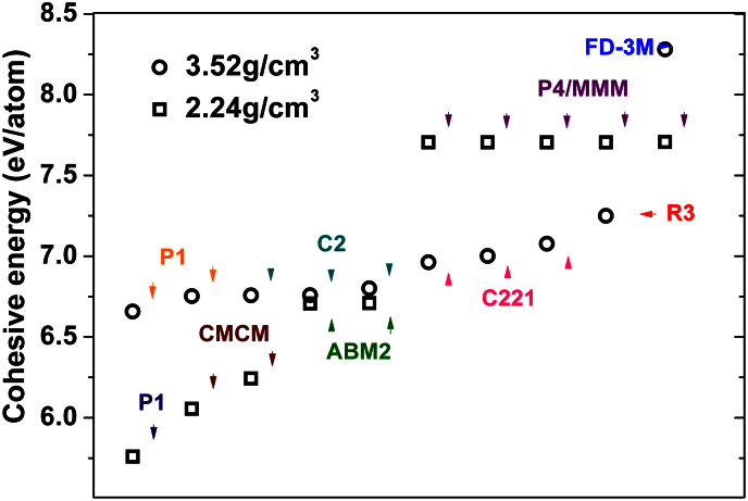
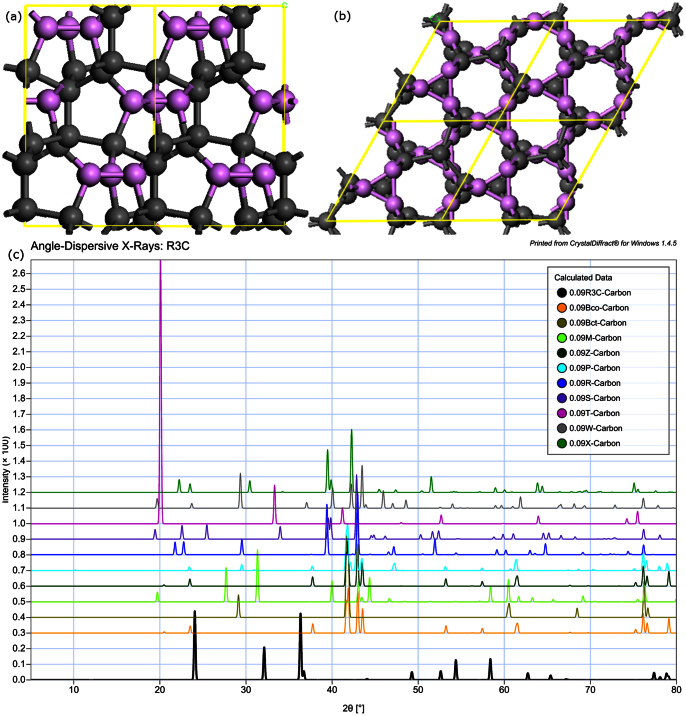
Figure 1 shows the cohesive energies and symmetries of twenty random structures generated by the SQ method. Clearly, these twenty structures cover many different atomic arrangement and symmetries. As already demonstrated in our previous work24, the SQ method efficiently reproduces metastable phases that may only be found experimentally by ultrafast cooling from liquid melt or by off-equilibrium synthesis. In addition, beyond the previously reported stable or metastable carbon phases (cubic diamond, monoclinic M-carbon10, body centered tetragonal bct-C4 carbon11, orthorhombic W carbon12, R carbon, P carbon13 and Cco-C8 carbon14), our simulations reveal a new trigonal structure with R3 symmetry. In Figure 2 (a) the detailed structure of this phase which we denote the R3-carbon phase is displayed. Within the unit cell of this structure, there are four inequivalent atoms bound with sp3 hybridized covalent bonds. The calculated atomic density and band gap are slightly lower than that of diamond. The calculated XRD-patterns of the R3-carbon phase along with the other carbon allotropes studied in this paper are shown in Figure 2 (b). R3-carbon phase is markedly different from S and B families of cold compressed graphite as is defined by Niu et al.17. The R3-carbon contains three-membered rings which enable a more compressed structure and serve as binding blocks between five and eight membered rings. Studying the calculated XRD-pattern of R3, it is clear that the R3-structure has its main peaks at 24.1 and 36.4 degrees 2θ, angles at which no other of the compressed graphite phases display any diffracted peaks. Moreover, all other carbon allotropes display main peaks between 40 and 45 degrees 2θ, whereas R3-carbon completely lacks intensity in this region.
Figure 1. The cohesive energies and symmetries of twenty random carbon structures with the densities of graphite (2.24 g/cm3) and diamond (3.52 g/cm3), respectively.
Figure 2.
(a) The R3-structure, the (001)-plane and the (010)-plane. Three-membered rings are colored in purple. (b) The calculated diffraction pattern of the R3 phase, Cco-C8 Carbon, Bct-Carbon, M-Carbon, Z-Carbon, P-Carbon, R-Carbon, S-Carbon, T-Carbon, W-Carbon and X-Carbon, respectively.
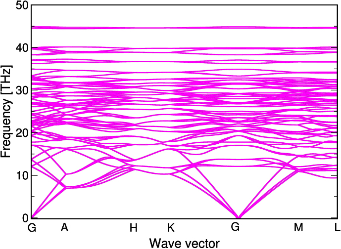
In order to investigate the dynamical stability of the R3-phase, phonon dispersion relationships have been calculated by Density Functional Perturbation Theory (DFPT) and the code of Phonopy (Fig. 3). The Brilliouin zone of this allotrope is complex due to its low symmetry and therefore phonon frequencies along paths in all three directions in space were studied (Г-A-H-K-Г-M-L-H). From the calculated phonon spectrum it is clear that there are no negative frequencies throughout the entire Brilliouin zone, which confirms that the R3-phase is dynamically stable.
Figure 3. The calculated phonon spectrum of the R3 phase along some selected paths in the Brillouin zone.
We first performed benchmark testing of the SQ method for a 4-atoms and a 8-atoms cell with densities of 2.24 g/cm3 and 3.52 g/cm3, respectively, corresponding to the density of graphite and diamond. To assess the accuracy of our first-principles total energy methods, we calculated the lattice constants and cohesive energies of diamond and graphite crystals using three exchange correlation functionals: the Perdew-Becke-Ernzerhof functional for solids and surfaces (PBEsol), a density functional constructed with a long-range dispersion correction (D2)25 and the van der Waals density functional (vdW-DF)26. In the bulk calculations, the Brillouin zone was sampled by a 10 × 10 × 10 k points mesh. The computed results are compared with experimental values in Table I. For the lattice constants, the results of DFT-D2 method shows best agreement with the experimental values, while the vdW-DF method yields the largest error bars. This sequence is completely opposite for the cohesive energy, where the error decreases in the order DFT-D2, DFT/PBEsol and vdW-DF. Moreover, the description of lattice constants and cohesive energy using vdW-DF method is comparable to previous calculations27. Considering the accuracy in the calculation of structures and cohesive energies as well as the computational time, we chose the PBEsol functional for the rest of all first-principles calculations in this paper.
Table 1. The lattice constants and cohesive energies of graphite and diamond computed by different exchange correlation functionals, including the Perdew-Becke-Ernzerhof functional for solids and surfaces (DFT/PBEsol), density functional constructed with a long-range dispersion correction (DFT-D2) and the van der Waals density functional (vdW-DF), compared with the relevant experimental data31. (The c/a ratio of graphite is set to 2.76 in present calculations).
| Graphite | PBEsol | vdW-DF | DFT-D2 | Expt. |
|---|---|---|---|---|
| a (Å) | 2.458 | 2.465 | 2.460 | 2.460 |
| EC(eV) | 8.29 | 7.99 | 8.41 | 7.37 |
| Diamond | PBEsol | vdW | DFT-D2 | Expt. |
| a (Å) | 3.554 | 3.574 | 3.545 | 3.54 |
| EC(eV) | 8.28 | 7.88 | 8.49 | 7.58 |
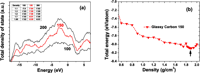
The validity of our glassy carbon model structure was assessed by computing the energy and total density of states (TDOS) of glassy carbon supercell models with different number of carbon atoms (100, 150, and 200 atoms). As shown in Figure 4a and its inset table, the total energy and the fingerprint peaks of TDOS converge at a supercell size of 150 atoms, further increasing the number of atoms in the GC model does not significantly change the total energy per carbon atom and the principal shape of TDOS. Previous studies have demonstrated that the supercell sizes of 150–200 atoms were enough for those amorphous phase investigations19,20,23,24. The total energy as a function of density (or volume) of the 150 atoms GC structure is plotted in Figure 4b. There is a local minimum in the total energy at a density of 1.88 g/cm3. Therefore, the dimension of the 150-atom supercell for the ground-state GC was fixed to be 14.41 Å (corresponding to a density of 1.88 g/cm3), respectively, which is within the range of the experimental densities for GC (1.02 g/cm3 to 2.1 ± 1 g/cm3 28) and agrees with the previous finding that the density of GC is lower than that of pure graphite (2.24 g/cm3)4.
Figure 4.
(a) Total density of state for increasing number of carbon atoms in the GC structure. The insert table displays the relationship between total energy with different density and number of carbon atoms in the model (b) The total as a function of density density of GC with 150 carbon atoms.
Overall speaking, the SQ method is able to locate a large number of possible metastable carbon allotropes with either sp2 or sp3-type bonding, which have been previously found by other random structural searches10,11,12,14 in a satisfactory manner. The ground-state graphite structure seems not reachable using this method without applying any symmetry constraint. This result differs from that found for monoatomic metals by Holmström et al.20, who found that the global energy minimum of the crystalline metal could be obtained for a small enough size of the cell. We attribute this difference firstly to the use of a cubic cell for the random guess and to the covalent nature of C-C bonds as well as the stronger tendency for carbon to amorphize compared to simple monoatomic metals. Nevertheless, it is reasonable to use the SQ-method for mapping the potential energy landscape of a disordered phase such as glassy carbon, as was also demonstrated in our previous paper24.
We further investigated the structural changes of GC under a series of hydrostatic pressures. The pressures were gradually applied as follows: the target volume was fixed to a certain value, and the cell geometry and atomic positions were relaxed simultaneously to obtain the final structures. We reduced the desired target volume step by step and repeated the above procedure until the external pressure reached 79 GPa. We first analyzed the structural characteristics of GC at ambient pressure, as presented in Table II. For the initial GC at ambient pressure, the density (ρ) is 1.88 g/cm3 and the mean coordination number (CN) is 2.8, both are lower than ρ = 2.24 g/cm3 and CN = 3 of graphite. With such low density and small coordination number, a 3-D network structure is still not achieved. Thus, the ground state structure of GC is composed of sp-hybridized chain segments that interlink to form some curved fragments of non-classical fullerenes, which include three-, four-, five-, six-, seven-, and eight- membered rings incorporating a very high sp2 ratio (90%). These sp2 fullerene fragments are stabilized by π bonding (C2 dimer). Moreover, there also exist sp3 hybridized atoms interlinking the sp2 dominated fullerene fragments, but the content is quite low. The binding type and relative content of bonding states of GC obtained by our stochastic quenching method are comparable to previous theoretical structural models2,3,5,6.
Table 2. Structural data for the GC under different pressures as calculated in this work, including mass density (density), the ratio of the C2 dimer, twofold coordinated atoms (sp), threefold coordinated atoms (sp2), threefold coordinated atoms (sp3), mean bond length (R1), average total coordination number (CN), bulk modulus (B), shear modulus (G) and Young's modulus (E). The theoretical results of bulk diamond are also shown for comparison.
| Pressure (GPa) | Density (g/cm3) | C2 dimer (%) | sp (%) | sp2 (%) | sp3 (%) | R1 (Å) | CN | B (GPa) | G (GPa) | E (GPa) |
| 0 | 1.88 | 9 | 12 | 72 | 7 | 1.463 | 2.86 | 97 | 36 | 96 |
| 3.61 | 2.09 | 9 | 10 | 70 | 11 | 1.462 | 2.95 | 111 | 62 | 156 |
| 6.56 | 2.35 | 12 | 3 | 60 | 25 | 1.470 | 3.10 | 138 | 87 | 216 |
| 8.46 | 2.50 | 13 | 0 | 53 | 34 | 1.476 | 3.23 | 150 | 101 | 248 |
| 9.86 | 2.68 | 9 | 0 | 49 | 42 | 1.496 | 3.43 | 240 | 154 | 381 |
| 18.49 | 2.89 | 11 | 0 | 44 | 45 | 1.488 | 3.4 | 256 | 152 | 389 |
| 30.3 | 3.13 | 15 | 0 | 32 | 53 | 1.485 | 3.49 | 315 | 215 | 525 |
| 55.9 | 3.48 | 13 | 0 | 12 | 75 | 1.48 | 3.7 | 416 | 270 | 666 |
| 58.3 | 3.54 | 13 | 0 | 9 | 78 | 1.48 | 3.72 | 434 | 314 | 759 |
| 79 | 3.75 | 11 | 0 | 0 | 89 | 1.475 | 3.78 | 521 | 368 | 893 |
| diamond | 3.52 | 0 | 0 | 0 | 100 | 1.54 | 4 | 447 | 540 | 1159 |
Figure 5 shows the representative GC structures under different external pressures of 0 GPa, 3.6 GPa, and 56 GPa, respectively. In general, these structures show distinct differences. For example, GC below 0 GPa has a two dimensional (2D) layered structure, while GC between 0 and 56 GPa exhibits a compact, three dimensional cross-linked network. Under compression, there is a clear tendency of increased density and the CN, as shown in Table II. Up to a high pressure of 79 GPa, the density rises to 3.75 g/cm3, which is even higher than for the ambient diamond (3.35 g/cm3). Moreover, the CN is also close to the maximal coordinate number of sp3 carbon, i.e. 4.
Figure 5. The GC structures under different pressure (0 GPa, 3.6 GPa, and 56 GPa).
The red carbon pairs represent the C2 dimer.
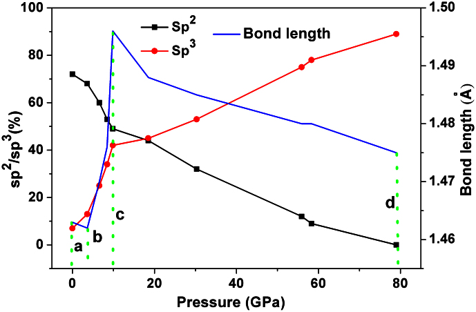
To gain deeper insight into the relationship between the detailed structures and static pressures, the evolution of local atomic structures of GC as a function of pressure can be monitored by the bond length and bonding states of C-C (dimer, sp, sp2 and sp3). Figure 6 and Table II show the bond length and fraction of sp, sp2, and sp3 in the static pressure range of 0–79 GPa. Upon compression, the variation of bond length can be divided into three distinct regions. From a to b (0–3.65 GPa), the bond length remains nearly invariant, the ratio of sp and sp2 decreases very slowly, and the sp3 content only increases from 7% to 11%. These results imply that the compression process of the broken or imperfect graphitic layer progressively approaches each other but does not reach the characteristic distance of C-C bonding. The region from b to c corresponds to a pressure range of 3.65–9.86 GPa, where the fraction of sp3 type bonding increases sharply. Meanwhile, the sp bonding vanishes gradually and the ratio of sp2-type bonding also reduces to nearly 40%. At a pressure of 9.86 GPa, the ratio of sp3 carbon (42%) is comparable to that of sp2 carbon (49%) and sp2 hybridized 2-D graphite-like structures transform to sp3 diamond-like ones. The loss of half of the π-bonds can be explained by the formation σ-bonds between imperfect graphitic layers as the layers continue to approach each other. Under further compression (the third region from c to d), the 2-D carbon sheets begin to deeper bend and further hybridize with each other. Therefore, the bonding states convert sequentially; as the pressure becomes larger than 50 GPa, the original sp2 type carbon totally convert to sp3 type.
Figure 6. The ratio of sp2 and sp3-type carbon bonding and bond length of GC with respect to external pressure up to 80 GPa.
The variation in sp3 fraction with pressure is compared to the calculated sp3 fractions in structures of amorphous carbon generated by the Car-Parrinello method and by the environment-dependent interaction potential (EDIP) developed by Marks et al.29,30. In their 64 atom simulations, they found a sp3 fraction of 57% at a density of 2.9 g/cm3, which should be compared to our calculated sp3 fraction of 45% at density of 2.89 g/cm3. Assuming that the fraction of dimers generated in the SQ method at this density (11%) would transform to sp3-like bonds as the structure is allowed to equilibrate at sufficient temperature, the sp3 content from our model will increase to 56% which is in close agreement with the results by Marks et al.29,30. Moreover, Marks et al.29,30 also found that the sp3 content would increase with increasing time of thermalization.
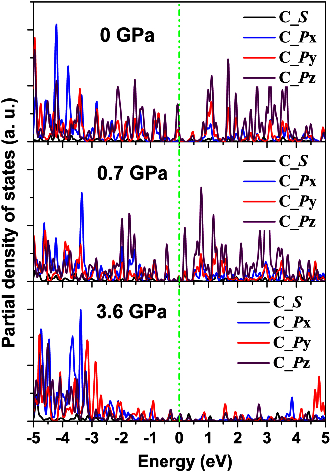
The variation of bond length of GC can be understood by the following two competing effects: high-pressure compression (which tends to shrinks the bond length) and the interconversion from sp2 to sp3 hybridization (which results in longer C-C bond length). As the pressure is less than 10 GPa, pressure-induced rehybridization from sp2 to sp3 dominates, and thus the C-C bond lengths are elongated31. This is a consequence of the formation of tetrahedral sp3 bonds through removing the unsaturated antibonding states of carbon, as is illustrated in Figure 7. C_p unsaturated bonds at the Fermi level as well as high energy antibonding states are prominent in the unpressurized structure. As the structure is gradually pressurized both these features diminish (Fig. 7). As a reference, the typical bond length of sp3 hybridized carbon is 1.54 Å (diamond), while 1.42 Å is the length of the σ-bond length in graphite31. Above 10 GPa, the sp3-hybridized carbon is more favorable in the amorphous structure, but the pressure-induced shrinking of the bond length is more pronounced. As a consequence, the bond lengths in all the structures under different pressures are all smaller than the standard C-C sp3 bond length, namely, 1.54 Å32. This can be understood from the presence of C2 dimers, which we will discuss in the following. Interestingly, up to a pressure of 79 GPa and a density of 3.65 g/cm3 we observed a certain number of C2 dimers in the GC, which are formed as a result of the π-interaction where triple like bonds of about 1.23 Å length are formed33. With increasing pressure, those C2 dimers do not vanish, that is, the density of the C2 dimers is not sensitive to the loading pressure on the GC. For example, the concentrations of the C2 dimer in the GC structures under pressures of 0 GPa, 6.56 GPa, 18.49 GPa, 55.9 GPa, and 79 GPa are 9%, 12%, 11%, 13% and 11%, respectively.
Figure 7. The evolution of orbital-projected density of states of the GC structure with pressure.
The Fermi level is set to 0 eV.
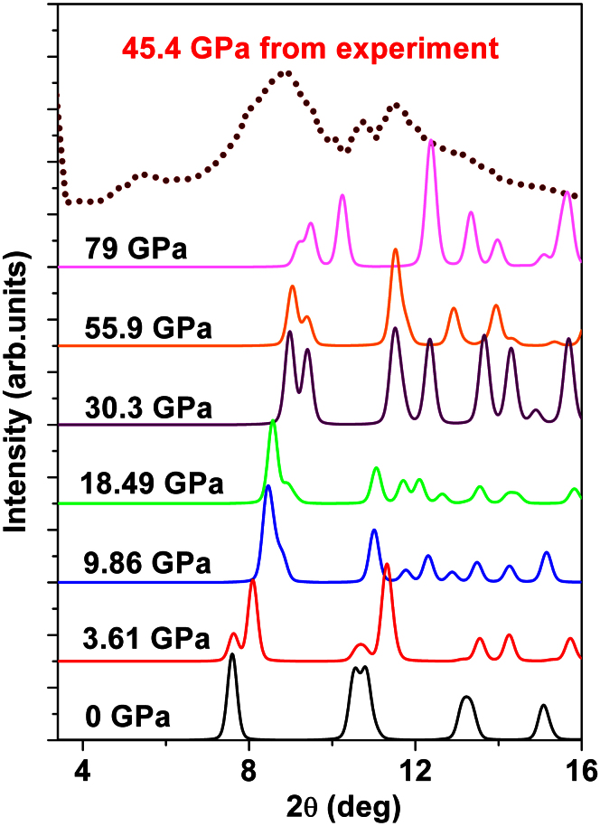
In Figure 8, the simulated XRD-patterns for the GC at different pressures are presented and compared with the experimental data measured by Lin et al.18 under an external pressure of 45.4 GPa. To generate the simulated XRD-pattern, a wavelength of λ = 0.3982 Å was used. Two peaks resembling the (002) interlayer distance and the (100) intralayer distance (and higher index planes) of polycrystalline graphite are found. The distance between these peaks stays rather constant, from 2.92 Å (0 GPa) to 3.11 Å (79 GPa) and Comparable to that of Lin et al.18 of 2.80 Å (45.4 GPa). The reduction in interplanar spacing (d) and the large pressure-induced shift of the peak corresponding to the distance between the soft (002) interlayers are also reproduced. However, the relative peak intensities do not compare well with Lin et al.18 and the low angle peak which appears at around 5.5 degrees 2θ in Lin's XRD-pattern is not reproduced. In our calculated XRD-spectra, the shift of the (002)-peak, corresponding to the decrease in interlayer distance is largest up to 30.3 GPa and seems to be related to the formation of a 3D-network. Above this threshold, there is no significant change of interlayer distance; instead splitting of both peaks occurs, indicating further symmetry breaking. The agreement with Lin et al. is overall relatively poor, suggesting that the GC allotrope found by the SQ-method is different to that synthesized by Lin et al.18.
Figure 8. XRD-patterns of GC at different pressures compared with experimental data taken from Ref. 18.
Our result deviates from the experimental findings by Lin et al.18 in two major aspects: (A) we find a considerably higher transition pressure, or rather, we do not find a complete sp2 to sp3-transformation; (B) we find C-C dimers, which display some π-bonding for all the pressures investigated in this work. Indeed, the occurrence of C2 dimers in our amorphous carbon structures is still reasonable, since the C2 dimer is also believed to be an important species or even a nucleation centre for the growth of diamond or nanotubes in experiments34,35. The existence of dimers is one of the reasons to why we do not obtain a 100% sp3 bond amorphous GC allotrope. One important cause of the difference between our calculated GC and the structure found by Lin et al.18 might be the synthesis method of the GC, which was not specified in the letter by Lin et al.18. The SQ-method does, as pointed out previously, well describe highly metastable structures formed in non-equilibrium processes, such as plasma-enhanced chemical vapor deposition or physical vapor deposition of thin films. Lin et al.18 instead uses a small bulk sample. Moreover, the temperature may also be an important parameter to consider. Therefore, MD simulations at 300 K, 700 K and 1300 K were performed for two of the high pressure GC phases (56 GPa and 79 GPa). The fraction of each bond type before and after heating is shown in Table III. We found the pairs of C2 dimers decreasing from 13 to 4 and from 11 to 1, respectively, when increasing temperature from 0 K to 1300 K. This suggests the C2 dimers would be considerably decreased in amount or dismissed if the experiments were performed at a high temperature.
Table 3. Structural data for the GC under 56 GPa and 79 GPa from MD simulations at 0 K, 300 K, 700 K, 1300 K, including the ratio of the C2 dimer, twofold coordinated atoms (sp), twofold coordinated atoms (sp2), and threefold coordinated atoms (sp3).
| Pressure (GPa) | T (K) | C2 dimer (%) | sp (%) | sp2 (%) | sp3 (%) |
|---|---|---|---|---|---|
| 56 | 0 | 13 | 0 | 12 | 75 |
| 300 | 8 | 0 | 9 | 83 | |
| 700 | 4 | 0 | 6 | 90 | |
| 1300 | 4 | 0 | 5 | 91 | |
| 79 | 0 | 11 | 0 | 0 | 89 |
| 300 | 3 | 0 | 2 | 95 | |
| 700 | 0 | 0 | 3 | 97 | |
| 1300 | 1 | 0 | 3 | 96 |
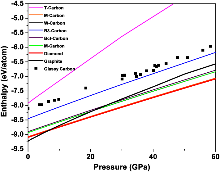
The thermodynamical stability, excluding the contribution from vibrational and mixing entropy, of pressure-induced GC can be determined by calculating the enthalpies H = E + PV, where E is the internal energy, P is the applied pressure, and V is the volume, without considering temperature. After optimizing the structures of GC under pressure, the value of the enthalpies can be obtained. The relationship between the calculated enthalpies and pressures for these pressure-dependent GCs in comparison with our calculated value of some crystalline phases (diamond, graphite, T-carbon, M-carbon, W-carbon, R3-carbon, Bct-C4 carbon, and Cco-C8 carbon) are plotted in Figure 9. According to the computed enthalpy, at 0 GPa GC is 0.5–1 eV less stable than some of the crystalline phases (diamond, graphite, M-carbon, W-carbon, R3-carbon, Bct-C4 carbon, Cco-C8 carbon); however, it is more stable than T-carbon. Under compression, M-carbon, W-carbon, Bct-C4 carbon, and Cco-C8 carbon become more stable than graphite beyond pressures of 15–25 GPa, which are comparable to the predictions made by many other groups10,11,12,14. In previous works, these phases were considered as the main products of cold compression of graphite. The R3-phase and glassy carbon display higher enthalpies (less negative) than graphite. More importantly, one can clearly see that the energy of GC under some pressures lies only 0.2 eV/atom above than R3-carbon. Such a small energy difference suggests a possible transition between them. However, to accurately consider also the kinetics of this transition, calculation of activation energy barriers for the diffusion of carbon from ideal sites in the crystalline R3-structure to the distorted positions of the GC-structure is required.
Figure 9. Enthalpy of formation calculated for different carbon allotropes (diamond, graphite, M-carbon, W-carbon, R3-carbon, Bct-C4 carbon, Cco-C8 carbon, T-carbon and GC) for pressures up to 60 GPa.
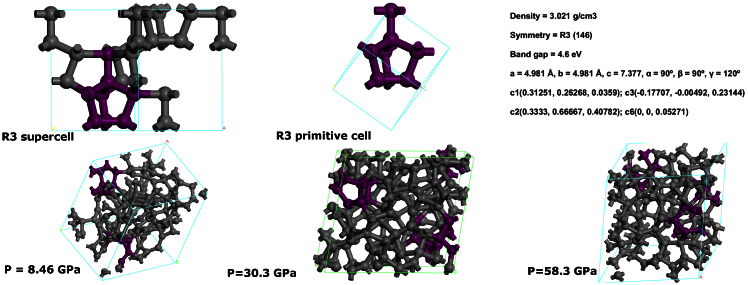
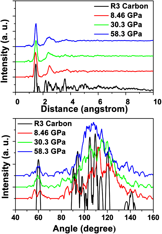
We now turn to explore the structural correlation between GC and R3-carbon, Figure 10 displays the structures of GC under three different pressures (8.46 GPa, 30.3 GPa and 58.3 GPa). After carefully analyzing the structures, we however found a very high content (around 10%) of a unit, similar to that of R3-carbon (or early phase). The early phase resembles crystalline R3-carbon but with distorted atomic positions or disconnecting one of the C-C bonds. As is seen in Figure 10, the early phase of GC contains three-membered carbon rings acting as building blocks between 5 and 8-membered rings, in proximity with R3-carbon. It is of interest to examine the radial distribution function (RDF) and angular distribution function (ADF) to further discuss the structural similarities, which are shown in Figure 11. These will describe the local order and orientation of carbon in the GCs, and is therefore better tool than XRD patterns. At a first glance, all three representative GC structures exhibit obviously amorphous features and the first nearest neighbor distance and second nearest neighbor distance of the RDF from our simulations are about 1.47 and 2.47 Å. Both the positions are consistent with the previous experimental36 and theoretical papers29,30. From ADF, we can clearly see there are four distinct peaks located at about 60°, 90°, 109°, 120° and 140° in the R3 structure. The 60° peak corresponds to the internal angles in the three-membered rings, whereas the 90° peak is attributed to bonds between these rings and the five- and eight-membered rings. 135° is the internal angle of an ideal octagon. In the R3-carbon the octagons are buckled, giving rise to peak contributions between 105 and 140°. Finally, the 109° peak corresponds to the dominant angle of sp3-hybridized carbon. From the calculated RDF, ADF and XRD-pattern of R3 we can conclude that such an unusual topology has not been reported for cold compressed graphite before and, furthermore, we find that characteristic peaks and characteristic Angles also exist in the GC structures under different pressure (8.46 GPa, 30.3 GPa, 58.3 GPa), which verify a similarity between the short-range order structures of the R3-carbon crystalline and the final glassy carbon phase.
Figure 10. Other possible transition paths from crystalline to amorphous carbon instead of quenching from liquid.
The R3-carbon structure can be seen as an initial unit of GC. (a) The primitive cell, supercell structure and atomic positions of the R3-crystalline carbon allotrope with trigonal symmetry of R3. (b) The structure of GC under different pressure (8.46 GPa, 30.3 GPa and 58.3 GPa). The cluster composed of purple carbon atoms is some representative units of the distorted R3-carbon.
Figure 11. Radial distribution function (RDF) and angle distribution function (ADF) of R3-carbon phase, GC under 8.48 GPa, 30.3 GPa, and 58.3 GPa from our DFT simulations.
Therefore, both a small energy difference and the close similarity of GC and the R3-carbon structure mentioned above suggests that the synthesis of GC from the R3-phase might be another route to produce the amorphous phase of carbon via a solid state amorphization (SSA). This phase transformation is different from the liquid to solid or gas to solid transition which both are generated by quenching the liquid melt or gas by ultra-fast cooling, accompanied by significant change of structures37,38.
SSA has been investigated by several studies reports39,40,41,42,43. Cahn and Johnson39 suggested SSA is a first-order phase transformation which can be caused by different driving forces, such as ion implantation, high energy particle irradiation, chemical diffusion, temperature or pressure. For example, Rehn et al.40 indicated that SSA was triggered by an elastic instability. Fecht41 also established a general theory for crystal-amorphous solid transitions and demonstrated that the crystalline phase can be ‘melted’ by a discontinuous increase of vacancy concentration. Especially, there are many four coordinate covalent systems observed where an order to disorder crystal to amorphous transition occurs. The instability of the diamond structure caused by phonon softening under compression may also lead to the transformation into the disordered state42. More interestingly, C60 fullerene under heating at moderate pressures will transform to the hard amorphous state, which is a similar case to our GC43. Commonly, solid state amorphization happen due to two basic features: a deep metastability of initial crystal and a similarity between the short-range order structures of the initial crystalline and final amorphous phase. Thus, based on our energetic analysis, RDF and ADF simulations, we can infer that by exerting some kind of perturbation (temperature, pressure, displacement, laser, ion bombardment, etc) on the crystalline R3-carbon, the long-range order may collapse and thus GC can be generated.
For sp3-carbon rich systems, the most important applications are their excellent mechanical properties inherited from diamond. Based on the equilibrium structures, we evaluated the mechanical properties of these GCs under different pressures. The bulk moduli, shear moduli, and Young's moduli of the GC under different pressures from our calculations are listed in Table II. For comparison, the elastic constant of diamond is also calculated using the same scheme. The calculated bulk, shear modulus and Young's modulus of 447 GPa, 540 GPa and 1159 GPa for diamond crystal are in good agreement with the experimental values of 442 GPa, 540 GPa and 1205 GPa44, respectively. Obviously, the bulk, shear, and Young's moduli of GC are strongly affected by the fraction of different bonding states. With increasing content of sp3 carbon bonding state, the Young's modulus rises gradually. As the pressure reaches 79 GPa, the content of sp3 bonding state reaches 90%, and the bulk moduli, shear moduli, and Young's moduli become 521 GPa, 368 GPa and 893 GPa, respectively. In our previous works45,46, we found Young's modulus a quite reliable parameter for estimating Vickers hardness of common covalent materials. If so, the pressure-induced GC structures are anticipated to possess a hardness approaching that of Diamond.
Discussion
In summary, we successfully generated one local minimum GC structure among a series of random structures with the SQ method. By means of DFT calculations we analyzed in detail its structural, thermodynamic and mechanical properties in a wide range of pressures (0–79 GPa). We present a theoretical picture of the pressure-induced phase transformation in GC, in proximity with previous experimental results. The transition pressure and obtained structure will depend on the specific synthesis method of the GC. The static pressure results in bond length changes and in a transition from sp to sp2 and sp3 carbon bonding states for GC. Consequently, the mechanical properties significantly vary due to the change of bonding type. With increasing pressure, the bulk moduli, shear moduli and Young's moduli approach diamond values. This may be an indication that off-equilibrium synthesis of glassy-carbon in bulk or thin film form, at high enough pressures may well result in a functional bulk material or coating with a hardness approaching that of diamond.
In addition, our results predict a new crystalline carbon allotrope named R3-carbon. Both the heat of formation and similar short-range order structures of R3-carbon and GC infer that this phase can be regarded as the embryo of amorphous GC. It provides another pathway to amorphization besides quenching from liquid melt or gas by ultra-fast cooling. This structure might also be tested as a seed layer for “epitaxial” growth of GC, utilizing their close-lying local structure and energetics. Therefore, we anticipate that the novel crystalline carbon allotrope and the promising pathway from this allotrope to synthesize amorphous carbon can be validated by future experiments.
Methods
In the present simulation, the ground state GC structures were generated by the stochastic quenching (SQ) method19,20,21,22,23, utilizing density functional theory (DFT) as implemented in the VASP package47. In our previous study of amorphous metal oxides by ultra-fast cooling from gas phase, it was shown that the SQ method provides a good description of the potential landscape of amorphous Al2O324. Initially, the atoms are distributed randomly within the simulation box, which in this case was a cubic supercell, where after the atomic positions were allowed to relax by the conjugate gradient method. The projector augmented wave (PAW) method48 was adopted and the 2s22p3 electrons of C were treated as valence electrons. A high energy cutoff of 700 eV was used for the plane-wave basis to ensure good convergence of the total energy and stress. The exchange-correlation interaction was described by the Perdew-Becke-Ernzerhofer functional (PBE) developed for solids and surfaces (PBEsol)49 within the gradient generalized approximation (GGA). The Brillouin zone was sampled in the Γ point only for the 150 atoms supercell of GC. During the relaxation process, we fixed the supercell geometry and turned the symmetry off. To ensure the reliability of the SQ method, we quenched 20 different random configurations with the density of graphite (2.24 g/cm3) and diamond (3.52 g/cm3), respectively. The volume and number of carbon atoms in the simulation cell were also determined carefully by repeating the above procedure.
The final structures obtained at different pressures were further optimized using higher cutoff of 1000 eV in order to evaluate the mechanical properties accurately. For the quasi-cubic supercell, the bulk modulus (B) was directly fitted from the derivative of Pressure–Volume (P–V) relationship under hydrostatic compression. Using the finite strain method50, we computed the elastic constants of the quasi-cubic supercell and then evaluated the isotropic shear modulus (G) using the Voigt–Reuss–Hill average scheme51. Consequently, the isotropic Young's modulus (E) can be calculated using the relationship: E = 9KG/(3K + G).
The dynamical stability of R3-carbon was investigated by phonon calculations in the software Phonopy52. The Perdew Becke Ernzerhof-functional (PBE)53, a k-point mesh of 6 × 6 × 6 k-points, centered in the Г-point and a cutoff of 750 eV, with the energy convergence limit of 10−8 eV was used to accurately relax the unit cell consisting of 24 atoms. The force constants were calculated in real space, within Density Functional Perturbation Theory (DPFT), where a 2 × 2 × 2 supercell consisting of 192 atoms, an energy cutoff of 750 eV and a k-point mesh including the Г-point only was used. XRD-patterns were calculated in the software CrystalDiffract® for Windows 1.4.5. using a simulated wavelength of Cu, λ = 1.54.
Author Contributions
X.J. and C.Å. wrote the main manuscript text and prepared the figures. J.Z. and R.A. have analyzed the results. X.J., C.A., L.P., J.Z. and R.A. have discussed & reviewed the manuscript.
Acknowledgments
We would like to acknowledge the Swedish Research Council (VR and FORMAS) and Stiftelsen J. Gust Richerts Minne (SWECO) for financial support. X. Jiang and P. Liu are thankful to the China scholarship council (CSC). R. Ahuja would like to acknowledge the Wenner-gren Foundation for financial support. C. Århammar would like to thank Prof. Duane Wallace et al. LANL, U.S.A. for the theoretical development of the SQ-method. SNIC and UPPMAX are acknowledged for providing computing time.
References
- Miller E. D., Nesting D. C. & Badding J. V. Quenchable Transparent Phase of Carbon. Chem. Mater. 9, 18–22 (1997). [Google Scholar]
- Ergun S. & Tiensuu V. H. Alicyclic Structures in Coals. Nature 183, 1668–1670 (1959). [Google Scholar]
- Jenkins G. M. & Kawamura K. Structure of Glassy Carbon. Nature 231, 175–176 (1971). [DOI] [PubMed] [Google Scholar]
- Pesin L. A. Review Structure and Properties of Glass-like Carbon. J. Mater. Sci. 37, 1–28 (2002). [Google Scholar]
- Pesin L. A. & Baitinger E. M. A New Structural Model of Glass-like Carbon. Carbon 40, 295–306 (2002). [Google Scholar]
- Harris P. J. F. Fullerene-related Structure of Commercial Glassy Carbons. Philos. Mag. 84, 3159–3167 (2004). [Google Scholar]
- Mao W. L. et al. Bonding Changes in Compressed Superhard Graphite. Science 302, 425–427 (2003). [DOI] [PubMed] [Google Scholar]
- Iwasa Y. et al. New Phases of C60 Synthesized at High Pressure. Science 264, 1570–1572 (1994). [DOI] [PubMed] [Google Scholar]
- Sundqvist B. Fullerenes under High Pressures. Adv. Phys. 48, 1–134 (1999). [Google Scholar]
- Li Q. et al. Superhard Monoclinic Polymorph of Carbon. Phys. Rev. Lett. 102, 175506 (2009). [DOI] [PubMed] [Google Scholar]
- Umemoto K., Wentzcovitch R. M., Saito S. & Miyake T. Body-Centered Tetragonal C4: A Viable sp3 Carbon Allotrope. Phys. Rev. Lett. 104, 125504 (2010). [DOI] [PubMed] [Google Scholar]
- Wang J. T., Chen C. f. & Kawazoe, Y. Low-Temperature Phase Transformation from Graphite to sp3 Orthorhombic Carbon. Phys. Rev. Lett. 106, 075501 (2011). [DOI] [PubMed] [Google Scholar]
- Niu H. et al. Families of Superhard Crystalline Carbon Allotropes Constructed via Cold Compression of Graphite and Nanotubes. Phys. Rev. Lett. 108, 135501 (2012). [DOI] [PubMed] [Google Scholar]
- Zhao Z. S. et al. Novel Superhard Carbon: C-Centered Orthorhombic C8. Phys. Rev. Lett. 107, 215502 (2011). [DOI] [PubMed] [Google Scholar]
- Wang Y., Panzik J. E., Kiefer B. & Lee K. K. M. Crystal Structure of Graphite under Room-temperature Compression and Decompression. Sci. Rep. 2, 520 (2012). [DOI] [PMC free article] [PubMed] [Google Scholar]
- Bundy F. P. Direct Conversion of Graphite to Diamond in Static Pressure Apparatus. Science 137, 1057–1058 (1962). [DOI] [PubMed] [Google Scholar]
- Irifune T., Kurio A., Sakamoto S., Inoue T. & Sumiya H. Materials: Ultrahard polycrystalline diamond from graphite. Nature 421, 599–600 (2003). [DOI] [PubMed] [Google Scholar]
- Lin Y. et al. Amorphous Diamond: A High-Pressure Superhard Carbon Allotrope. Phys. Rev. Lett. 107, 175504 (2011). [DOI] [PubMed] [Google Scholar]
- Wallace D. C. Evaluation of Thermodynamic Functions of Elemental Crystals and Liquids. Phys. Rev. E 56, 1981–1986 (1997). [Google Scholar]
- Holmström E. et al. Ab Initio Method for Locating Characteristic Potential-energy Minima of Liquids. Phys. Rev. E 80, 051111 (2009). [DOI] [PubMed] [Google Scholar]
- Amézaga A. et al. Quantitative Local Environment Characterization in Amorphous Oxides. Phys. Rev. B 81, 014210 (2010). [Google Scholar]
- Bock N. et al. Liquid-state Properties from First-principles Density Functional Theory Calculations: Static Properties. Phys. Rev. B 82, 144101 (2010). [Google Scholar]
- Holmström E. et al. Structure Discovery for Metallic Glasses using Stochastic Quenching. Phys. Rev. B 82, 024203 (2010). [Google Scholar]
- Århammar C. et al. Unveiling the Complex Electronic Structure of Amorphous Metal Oxides. P. Nat. Acad. Sci. Usa. 108, 6355–6360 (2011). [Google Scholar]
- Grimme S. Semiempirical GGA-type Density Functional Constructed with a Long-range Dispersion Correction. J. Comput. Chem. 27, 1787–1799 (2006). [DOI] [PubMed] [Google Scholar]
- Dion M., Rydberg H., Schröder E., Langreth D. C. & Lundqvist B. I. Van der Waals Density Functional for General Geometries. Phys. Rev. Lett. 92, 246401 (2004). [DOI] [PubMed] [Google Scholar]
- Klimeš J., Bowler D. R. & Michaelides A. Van der Waals Density Functionals Applied to Solids. Phys. Rev. B 83, 195131 (2011). [Google Scholar]
- Townsend S. J., Lenosky T. J., Muller D. A., Nichols C. S. & Elser V. Negatively Curved Graphitic Sheet Model of Amorphous Carbon. Phys. Rev. Lett. 69, 921–924 (1992). [DOI] [PubMed] [Google Scholar]
- Marks N. A. et al. Comparison of Density-functional, Tight-binding, and Empirical Methods for the Simulation of Amorphous Carbon. Phys. Rev. B 65, 075411 (2002). [Google Scholar]
- Marks N. A., McKenzie D. R., Pailthorpe B. A., Bernasconi M. & Parrinello M. Ab Initio Simulations of Tetrahedral Amorphous Carbon. Phys. Rev. B 54, 9703–9714 (1996). [DOI] [PubMed] [Google Scholar]
- Kittel C. Introduction to Solid State Physics. (Wiley, 1996). [Google Scholar]
- Mackay A. L. & Terrones H. Diamond from Graphite. Nature 352, 762–762 (1991).1881433 [Google Scholar]
- Stephan U., Frauenheim T., Blaudeck P. & Jungnickel G. π Bonding versus Electronic-defect Generation: An Examination of Band-gap Properties in Amorphous Carbon. Phys. Rev. B 50, 1489–1501 (1994). [DOI] [PubMed] [Google Scholar]
- Goyette A. N. et al. Spectroscopic Determination of Carbon Dimer Densities in Plasmas. J. Phys. D. Appl. Phys. 31, 1975 (1998). [Google Scholar]
- Sternberg M., Zapol P. & Curtiss L. A. Carbon Dimers on the Diamond (100) Surface: Growth and Nucleation. Phys. Rev. B 68, 205330 (2003). [Google Scholar]
- Gilkes K. W. R., Gaskell P. H. & Robertson J. Comparison of Neutron-scattering Data for Tetrahedral Amorphous Carbon with Structural Models. Phys. Rev. B 51, 12303–12312 (1995). [DOI] [PubMed] [Google Scholar]
- Raoux S., Welnic W. & Ielmini D. Phase Change Materials and Their Application to Nonvolatile Memories. Chem. Rev. 110, 240–267 (2009). [DOI] [PubMed] [Google Scholar]
- Kolobov A. V., Krbal M., Fons P., Tominaga J. & Uruga T. Distortion-triggered Loss of Long-range Order in Solids with Bonding Energy Hierarchy. Nat. Chem. 3, 311–316 (2011). [DOI] [PubMed] [Google Scholar]
- Johnson W. L. Thermodynamic and Kinetic Aspects of the Crystal to Glass Transformation in Metallic Materials. Prog. Mater. Sci. 30, 81–134 (1986). [Google Scholar]
- Rehn L. E., Okamoto P. R., Pearson J., Bhadra R. & Grimsditch M. Solid-State Amorphization of Zr3Al: Evidence of an Elastic Instability and First-Order Phase Transformation. Phys. Rev. Lett. 59, 2987–2990 (1987). [DOI] [PubMed] [Google Scholar]
- Fecht H. J. Defect-induced Melting and Solid-state Amorphization. Nature 356, 133–135 (1992). [Google Scholar]
- Lyapin A. G. & Brazhkin V. V. Pressure-induced Lattice Instability and Solid-state Amorphization. Phys. Rev. B 54, 12036–12048 (1996). [DOI] [PubMed] [Google Scholar]
- Vadim V. B. et al. Bulk Nanostructured Carbon Phases Prepared from C60: Approaching the ‘Ideal’ Hardness. J Phys.: Conden. Matt. 19, 236209 (2007). [Google Scholar]
- Brazhkin V. V., Lyapin A. G. & Hemley R. J. Harder than Diamond: Dreams and Reality. Philos. Mag. A 82, 231–253 (2002). [Google Scholar]
- Jiang X., Zhao J. J., Wu A. M., Bai Y. Z. & Jiang X. Mechanical and Electronic Properties of B12-based Ternary Crystals of Orthorhombic Phase. J. Phys.: Conden. Matt. 22, 315503 (2010). [DOI] [PubMed] [Google Scholar]
- Jiang X., Zhao J. & Jiang X. Correlation Between Hardness and Elastic Moduli of the Covalent Crystals. Comp. Mater. Sci. 50, 2287–2290 (2011). [Google Scholar]
- Kresse G. & Furthmüller J. Efficient Iterative Schemes for Ab Initio Total-Energy Calculations Using a Plane-wave Basis Set. Phys. Rev. B 54, 11169-11186 (1996). [DOI] [PubMed] [Google Scholar]
- Blöchl P. E. Projector Augmented-wave Method. Phys. Rev. B 50, 17953–17979 (1994). [DOI] [PubMed] [Google Scholar]
- Perdew J. P. et al. Restoring the Density-Gradient Expansion for Exchange in Solids and Surfaces. Phys. Rev. Lett. 100, 136406 (2008). [DOI] [PubMed] [Google Scholar]
- Zhao J., Winey J. M. & Gupta Y. M. First-principles Calculations of Second- and Third-order Elastic Constants for Single Crystals of Arbitrary Symmetry. Phys. Rev. B 75, 094105 (2007). [Google Scholar]
- Hill R. The Elastic Behaviour of a Crystalline Aggregate. Proc. Phys. Soc. A 65, 349 (1952). [Google Scholar]
- Togo A., Oba F. & Tanaka I. First-principles Calculations of the Ferroelastic Transition between Rutile-type and CaCl2-type SiO2 at High Pressures. Phys. Rev. B 78, 134106 (2008). [Google Scholar]
- Perdew J. P., Burke K. & Ernzerhof M. Generalized Gradient Approximation Made Simple. Phys. Rev. Lett. 77, 3865–3868 (1996). [DOI] [PubMed] [Google Scholar]


