Abstract
Multiprotein adsorption of hen egg white lysozyme at a model charged ionic surface is studied using fully atomistic molecular dynamics simulations. Simulations with two, three, and five proteins, in various orientations with respect the surface, are performed over a 100 ns time scale. Mutated proteins with point mutations at the major (Arg128 and Arg125) and minor (Arg68) surface adsorption sites are also studied. The 100 ns time scale used is sufficient to observe protein translations, rotations, adsorption, and aggregation. Two competing processes of particular interest are observed, namely surface adsorption and protein–protein aggregation. At low protein concentration, the proteins first adsorb in isolation and can then reorientate on the surface to aggregate. At high concentration, the proteins aggregate in the solution and then adsorb in nonspecific ways. This work demonstrates the role of protein concentration in adsorption, indicates the residues involved in both types of interaction (protein–protein and protein–surface), and gives an insight into processes to be considered in the development of new functionalized material systems.
Introduction
Protein–protein and protein–surface interactions are essential for numerous medical and technological material systems and their applications.1 Biomaterials play an enormous role in medicine,2 and in particular nanoparticles coated by proteins may be widely used as drug delivery systems or in vitro diagnostics.3 In recent work we have employed molecular dynamics simulations to elucidate single hen egg white lysozyme (HEWL) adsorption mechanisms on a model charged ionic surface,4 successfully identifying the protein adsorption sites and key residues in good agreement with experiment. The work also revealed further details such as the order of events in the adsorption process, the importance of internal protein flexibility, and the role of electrostatic interactions.4−7 In this paper we build on this work and analyze simulations of multiprotein adsorption, giving new insight into the role of protein–protein interactions in the adsorption process.
Because of its modest size with 129 residues, its globular shape in solution, and its low cost, HEWL is one of the most studied proteins with a well-characterized structure.8 This ellipsoidal protein is categorized as a “hard” protein; despite its internal flexibility, it does not easily change its structure,9 behavior confirmed in our previous single-protein adsorption simulations.4,6,7 We have shown that HEWL possesses two charged-surface adsorption sites: the major one located at the N,C-terminal protein face comprising Arg128, Arg125, Arg5, and Lys1 and the minor one comprising Arg68 which is used only accidentally and is located almost opposite to the N,C-terminal face.4,6,7 Figure 1 shows the HEWL protein with the key residues labeled. Our atomistic molecular dynamics results agree with previous experimental and theoretical studies.10−13
Figure 1.
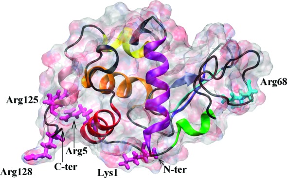
HEWL molecule. The protein surface is indicated as a ghost surface colored by charge; secondary structure elements are shown as a cartoon. In domain α, helix A (residues 5–16) is indicated by red, helix B (25–37) by orange, helix C (88–101) by purple, helix D (109–116) by yellow, and helix 310 (120–125) by pink. In domain β, the β1 structure (residues 43–46) is indicated by blue, β2 (51–54) by cyan, β3 (58–60) by ice-blue, and helix 310 (79–84) by green. The main residues creating the major adsorption site (Lys1, Arg5, Arg125, and Arg128) and the minor one (Arg68) are indicated by light pink and light cyan licorice, respectively.
Real protein layer formation at a surface naturally involves the interactions of the proteins with one another as well as with the surface. Insight into these interactions has come from in-liquid atomic force microscopy (AFM) experiments.14−16 In these experiments, very low HEWL concentrations are used so that the protein layer formation occurs over many hours, allowing the evolution of the submonolayer surface protein layer to be monitored. It is found that the proteins cluster together on the surface, with the clusters growing by the surface diffusion and aggregation of monomers and indeed clusters themselves, with cluster mobility decreasing inversely with size. Statistical analysis of the AFM images in comparison with Monte Carlo simulation reveals that on the charged ionic mica surface, the HEWL surface mobility is low but significant at about 4.5–9 × 10–16 cm2/s.15,16
Building on our previous work with single protein adsorption, we aim to obtain new insight into the surface interactions using fully atomistic molecular dynamics simulations of multiprotein adsorption. Although the diffusion of clusters observed experimentally is far beyond the time scales available to this type of simulation, we can nevertheless learn details of the interactions between the proteins themselves and with the surface. It is known that in solution lysozyme readily forms dimers.17−20 It is therefore appropriate to investigate this process using molecular dynamics and to see how it is modified when surface adsorption provides a competitive alternative.
Here we will present MD studies of the multiprotein adsorption of HEWL on our model charged ionic surface. We employ a 100 ns time scale which, as our simulations for single protein adsorption have shown,4−7 is sufficient to observe protein adsorption and reorientation on the surface. As we have shown previously, such a time scale also allows protein rotations and translations in solution and further nonspecific adsorption to the surface. Analysis of protein diffusion indicated that single proteins are mobile in the solution and can be on the surface when weakly adsorbed using Arg68.4,7 Therefore we can assume that 100 ns is also enough to observe protein oligomerization both in solution and at the surface in more crowded protein systems. Indeed, within this time scale the early events in the dimer formation have been observed in this present study, but the continuation of the trajectory beyond 100 ns was required to monitor the whole process.
We assume adsorption to be specific when the protein uses one of its adsorption sites identified for single protein adsorption (i.e., the N,C-terminal face or Arg68)4,6,7 and nonspecific if uses any other residue to interact with the surface directly or indirectly through hydrogen bonds (H-bonds) with surface water layers. Typically an arginine (Arg) residue is used, since its side chain is long, flexible, and charged and may create hydrogen bonds with water molecules. As we shall show, the scenario chosen does depend on local protein concentration. In particular, if the concentration is high, protein–protein interactions are favored and oligomerization before adsorption dominates. Since the oligomers are less mobile than monomers, rotations in solution are slower, and as a result, the oligomer can be trapped in a local energy minimum and so adsorb nonspecifically using any available residue. An additional complication emerges because the main surface adsorption site at the N,C-terminal face can often be involved in the protein–protein interactions, providing an element of competition between various interactions.
Despite its limitations, namely the simulation time, number of molecules in the simulation cell, and relatively high concentrations, simulations of multiprotein adsorption reproduce the experimental environment much better than single-protein systems. The results therefore have huge implications for understanding the role of various factors important in protein adsorption and hence will have an impact in the design of new materials dedicated to protein immobilization and surface functionalization.
Methodology
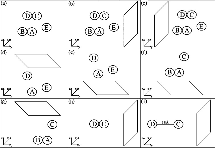
We study systems containing two, three, and five HEWL molecules corresponding to protein concentrations ∼60, ∼90, and ∼150 g/L, respectively. All simulations were performed in a water box at pH 7, and with the surface present at four different orientations. Taking into account calculations for mutated proteins (mainly with point mutations at Arg128, Arg125, and Arg68 in various combinations), we obtain 25 100 ns trajectories of the HEWL assembly in the close proximity to the model charged ionic surface. Nine of these surface trajectories will be discussed in detail here (the others support our interpretation without adding new information). One additional trajectory was calculated for five proteins in the water box without any surface present, to be used as a reference system. Figure 2 illustrates the various simulations performed in this study. Simulations with mutations are annotated as in R128G, which means that Arg128 has been replaced with Gly128. Computational model details may be found in the Methods Section given in the Supporting Information. Note the similarities with the protocol previously used for single protein simulations.4−7
Figure 2.
Schematic diagram illustrating the simulations performed in this study. The typical trajectory length was 100 ns. (a) The protein assembly in water only (water is not shown). (b) Five proteins with the surface in the x,z plane in orientation 1. Due to mutations R128G alone and R128G together with R68G on all five proteins, independent starts and various size of simulation cell, the total number of trajectories peformed in this configuration was 8. (c) Five proteins with the surface in the x,z plane in orientation 2; one trajectory was run for this orientation. (d) The three protein system for ADE protein molecules with the surface in the x,y plane in orientation 1. The number of independent runs was 7, including runs with mutations R128G alone, R128G together with R68G, R128G together with R125G and L129G together with R21G on all three proteins. (e) The three protein system for ADE protein molecules with the surface in the x,y plane in orientation 2; one trajectory was run for this orientation. (f) The three protein system for ABC protein molecules with the surface in the x,y plane in orientation 1. (g) The three protein system for ABC protein molecules with the surface in the x,y plane in orientation 2. For each ABC orientation one 100 ns trajectory was performed. (h) Two protein system for molecules C and D oriented as in the crystal. The total number of trajectories was 4: one simulation for native proteins, one for R128G mutation on protein C only, one for R128G mutation on protein D only, and finally one simulation for R128G mutation on both proteins. (i) Two protein system for molecules C and D oriented as in the crystal but translated by 20 Å which results in a protein–protein separation of 13 Å. One trajectory for the native proteins and one for R128G mutation on each molecule was performed.
Results and Discussion
Two Protein System
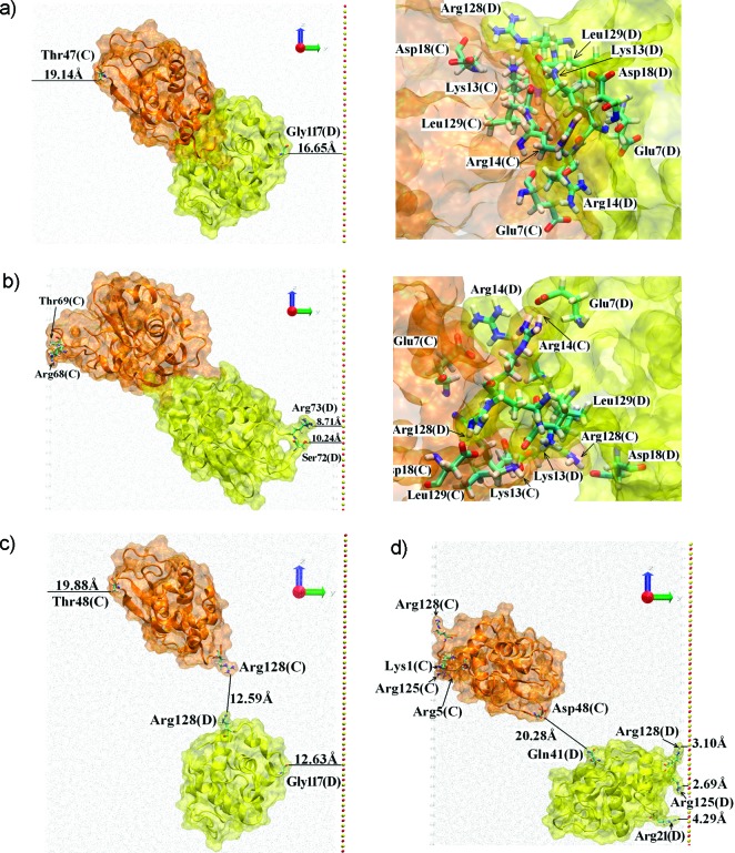
The simulations with two proteins (C and D in Figure 2) show that there is a competition between surface adsorption and dimer formation. We consider first the case when proteins C and D start close together in positions taken from the bulk HEWL crystal structure (symmetry group P43212), thereby forming a dimer in solution (see Figure 3a). The final position of the dimer after a 100 ns trajectory is shown in Figure 3b. The protein–protein interactions at the dimer interface, namely Arg128(C)-Asp18(D), Asp18(C)-Arg128(D), Arg14(C)-Glu7(D), Glu7(C)-Arg14(D), Leu129(C)-Lys13(D), and Lys13(C)-Leu129(D) remained unchanged throughout the trajectory. Details about the CD dimer interface are given in Table 1.
Figure 3.
CD dimer. Proteins are shown as a ghost orange (protein C) and yellow (protein D) surface, the secondary structure is indicated by a cartoon. Important residues are shown by licorice with the coloring scheme: oxygen (red), hydrogen (white), carbon (magenta), and nitrogen (blue). Water molecules are indicated by gray dots. The surface is shown as red and yellow CPKs, for oxygen and silica atoms respectively. Important residues as well as distances are labeled. (a) The initial structure of the CD dimer positioned as in the crystal structure. The inset shows residues involved in the dimer interface. (b) The final structure (after 100 ns trajectory) of the CD dimer. The inset shows residues involved in the dimer interface. (c) The initial structure of the CD dimer with one protein translated by 20 Å with respect to the other. (d) The final structure (after 100 ns trajectory) of this separated CD dimer. Note that the proteins shown in panels b and d, as discussed in the text, adsorbed to the image of the surface located on the left side of the box. The image of the surface is produced by using periodic boundary conditions for the system and visualized by the highly ordered water molecules. For details about the image of the surface see results for single-protein adsorption.4−7
Table 1. Possible H-Bonds Observed at Dimer Interfacesa.
| five proteins trajectory | |||
|---|---|---|---|
| AB dimer |
CD dimer |
||
| atoms of A and B | D (Å) | atoms of C and D | D (Å) |
| Arg61HE-Leu129OT1 | 1.80 | Arg14HH11-Leu129OT2 | 1.80 |
| Arg61HH22-Leu129OT2 | 1.55 | Arg14HH21-LeuOT1 | 1.76 |
| Arg112HH11-Asp119OD1 | 1.86 | Glu7OE2-Lys1HZ3 or | 1.69 |
| Arg112HH21-Asp119OD2 | 1.75 | Glu7OE2-Tyr20HH | 1.67 |
| Asp48OD1-Arg125HH22 | 1.72 | Leu129OT2-Arg128HH12 | 1.69 |
| DE dimer | |
|---|---|
| atoms of D and E | D (Å) |
| Arg68HH22-Leu129OT1 | 1.87 |
| three proteins trajectory | |||
|---|---|---|---|
| dimer DE after 100 ns |
dimer DE after 200 ns |
||
| atoms of D and E | D (Å) | atoms of D and E | D (Å) |
| Leu129OT1-Arg21HH11 | 1.73 | Leu129OT1-Arg21HH21 or | 1.66 |
| Leu129OT2-Arg21HH21 | 1.91 | Leu129OT1-Lys13HZ2 | 1.70 |
| Leu129OT2-Arg21HH11 or | 1.70 | ||
| Leu129OT2-Lys13HZ2 | 2.05 | ||
| Tyr20HH-Asp101OD1 | 1.72 | ||
| statistically independent dimer DE after 200 ns |
statistically independent dimer DE after 300 ns |
||
|---|---|---|---|
| atoms of D and E | D (Å) | atoms of D and E | D (Å) |
| Leu129OT2-Lys116HZ2 | 1.69 | Leu129OT2-Lys116HZ1 | 1.62 |
| Tyr20HH-Asp48OD1 | 1.80 | ||
| two proteins trajectory | |
|---|---|
| CD dimer | |
| atoms of C and D | D (Å) |
| Arg14HH11-Glu7OE1 | 1.52 |
| Arg14HH21-Glu7OE2 | 1.82 |
| Arg128HH11-Asp18OD2 | 1.86 |
| Arg128HH21-Asp18OD2 | 1.88 |
| Asp18OD1-Arg128HH21 | 1.85 |
| Asp18OD2-Arg128HH11 | 1.72 |
| Glu7OE1-Arg14HE | 2.00 |
| Glu7OE2-Arg14HH22 | 1.67 |
| Leu129OT1-Lys13HZ1 | 1.65 |
| Lys13HZ2-Leu129OT1 | 2.46 |
| Lys13HZ3-Leu129OT2 | 1.73 |
Order of atoms involved is alphabetical, first atom in the possible bond belongs to protein A, second to protein B (C and D or D and E, respectively, in CD and DE dimer). In the next column, the distance D is given in Å.
The protein dimer essentially evolved as a single body and adsorbed to the image of the surface using Arg68 from protein C. This protein had to travel a distance about 20 Å toward the image; the initial distance between the protein and the surface was about 22 Å, while the final one was only 2 Å. It is worth noting that adsorption at Arg68 was found in single protein simulations and identified as a minor adsorption site.4 Two other residues, Thr69 and Arg73, also participate in the interaction of protein C with the image of the surface. Note that the dimer could not adsorb in the preferred, stronger way since the N,C-terminal face of both proteins are employed in the dimer interface. An indication that the adsorption is not a preferred interaction is provided by the orientation of proteins’ dipole moments; neither dipole was oriented toward the surface or its image. The long loop connecting β-sheet B3 and α-helix310 in the β-domain (residues 61–78) of protein C has changed its orientation, detaching from the protein surface and exposing Arg68 to the image. Similar behavior is observed in protein D; the long loop is detached from the rest of the protein, and two side chains, Arg73 and Ser72, are exposed to the surface. However, in this case the distance is too big (∼10 Å) to be considered as a contact with the surface.4 Mutations at positions Arg128 and/or Arg125 on both proteins, mutating the arginines to glysines, made the dimer interface weaker but did not cause the dimer to dissociate on our 100 ns time scale, thereby leaving the adsorption pattern unchanged (data not shown). The dimer used in this study might be a candidate for the strongly bound HEWL dimer observed recently.20
To check the hypothesis about the competition between the adsorption and oligomerization processes we have performed further simulations that start with a dissociated dimer. Here one protein was translated by 20 Å away from the other. Since the proteins were overlapping, the distance separating the protein surfaces was 12.6 Å (see Figure 3c) at the start of the simulation. In this case proteins did not interact before adsorption and so adsorbed as a single proteins; protein D adsorbed to the surface while protein C adsorbed to the surface’s image. Both proteins used their N,C-terminal face to adsorb. Arg128, Arg125, Arg5, and Lys1 of protein C were strongly interacting with the image, whereas in the case of protein D, Arg128, Arg125, and additionally Arg21 were involved in contacts with the surface (see Figure 3d). The general adsorption mechanism was similar to those described for single protein adsorption,4 and the final protein orientations can be described as end-on with the angle ∼80° between the dipole moment (almost equivalent to the protein long axis) and the surface (or its image in the case of protein C). Since the dipole moment behavior was essentially the same as in the single-protein adsorption studies,4−7 it is not shown here to keep the figures clear. Figure 3d shows that upon adsorption both proteins have flattened their surfaces.
The detailed behavior of the dimer in its crystal form as well as the dissociated one is illustrated by movies dimer.avi and dimer_trans.avi provided in the Supporting Information.
Three Protein System
One of the objectives in this work is to discover how preadsorbed proteins can create clusters on the surface. This type of behavior was detected in a trajectory using three protein molecules (see Figure 4) and agrees with experimentally observed HEWL tendency for dimer formation on a silicon oxide surface21 or very close to a silica–titania surface, where they are able to sense the surface.22
Figure 4.
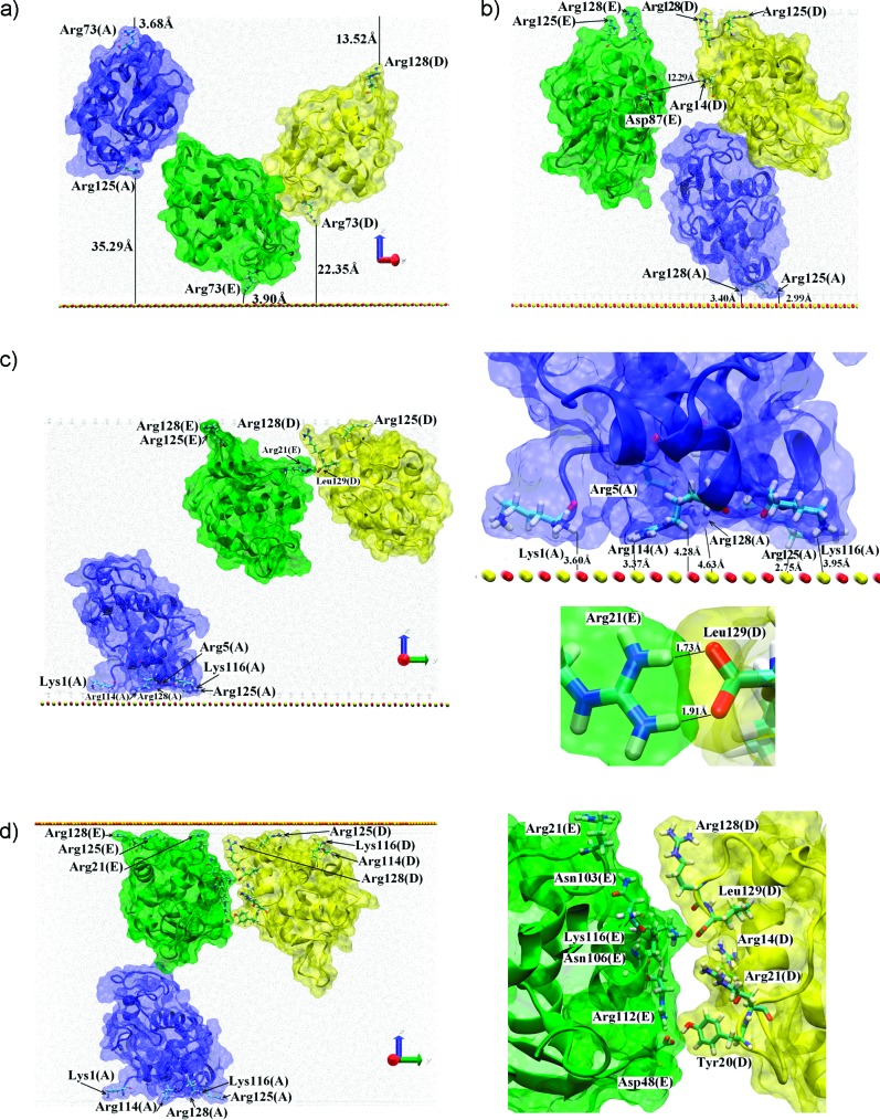
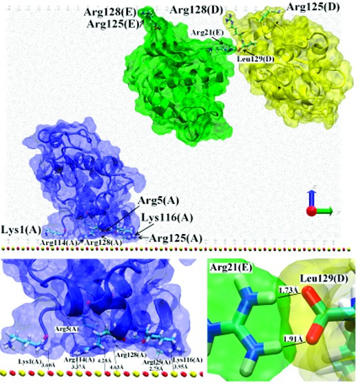
Three protein system with A (blue), D (yellow), and E (green) located as in the crystal structure. The coloring scheme is the same as in Figure 3. (a) The initial structure with no contacts between proteins. (b) The three protein system after 40 ns of the trajectory. (c) The system after the 100 ns of trajectory. The lower inset shows interactions between proteins D and E, while the upper one shows interactions between protein A adsorbed to the surface and the surface atoms. (d) The A, D, E system after a 200 ns trajectory. The inset shows the DE dimer interface.
Proteins A, D, and E from Figure 2 were initially located relatively close to each other (each protein had a neighbor less than 10 Å away) but no dimers were formed (see Figure 4a). After 40 ns (Figure 4b), all three proteins were adsorbed to the surface or its image using their N,C-terminal face, in orientations somewhere between the side-on and end-on ways. This remained the case after 100 ns (Figure 4c). Surprisingly, the initial distance to the surface did not determine where the adsorption occurred, which instead was determined by each protein’s dipole moment. Initially protein A was close (∼3.68 Å) to the image of the surface, while protein E was close (∼3.90 Å) to the surface and protein D was located in the middle of the simulation box. Then protein A adsorbed to the surface using Arg128, Arg125, Lys116, Arg114, Arg5, and Lys1 (the N,C-terminal face), while proteins D and E adsorbed to the image of the surface by Arg128, Arg125, and in the case of protein D also Lys1. The dipole moments were oriented toward these adsorption surfaces. The proteins adsorbed independently; the initial distance between proteins D and E was ∼10 Å, and after about 40 ns, these proteins had adsorbed with separation ∼13 Å (see Figure 4b).
After adsorption the anchored proteins (mainly protein D) started to rotate toward each other and expose side chains to create H-bonds and/or salt-bridges. In the final structure at 100 ns Leu129(D) creates two contacts with Arg21(E) (for details see Figure 4c and Table 1). This seems to be the start of dimer formation. Continuation of the trajectory supports this view; after another 100 ns the dimer was more tightly bonded with the interface containing more residues from both proteins: Leu129, Arg128, Arg21, Tyr20, Asn19 and Lys13 from protein D and Lys116, Asn103, Asp101 and Arg21 from protein E (for details see the movie cluster3.avi provided in the Supporting Information). The geometry indicates that at the interface several H-bonds may be created: Tyr20(D)HH-Asp101(E)OD1 (1.72 Å), Leu129(D)OT2-Arg21(E)HH11 (1.70 Å), and Leu129(D)OT1-Arg21(E)HH21 (1.66 Å). The last two may be replaced by alternative contacts: Leu129(D)OT2-Lys13(E)HZ2 (2.05 Å) or Leu129(D)OT1-Lys13(E)HZ2 (1.70 Å), see also Table 1. The orientation of Arg73 from both proteins suggests that in the longer trajectory those residues may also take a part in the protein–protein interactions. No substantial changes in the protein–surface interface were observed; in both proteins Arg125 and Arg128 residues still played a crucial, anchoring role. Note that Arg128(D) was simultaneously involved in both type of interaction, with the surface and with the other protein.
In another statistically independent version of the simulation we have continued the described trajectory with the surface located opposite to its position shown on Figure 4c (proteins D and E adsorbed to the surface and protein A adsorbed to the image). Similar behavior was seen; the protein–surface interface did not change much and the protein–protein interactions became stronger (see Figure 4d). The list of residues involved in the dimer formation is also similar: Leu129, Arg128, Arg21, Tyr20 and Arg14 from protein D and Lys116, Arg112, Asn106, Asn103, Asp48, and Arg21 from protein E. As listed in Table 1 and shown in Figure 4d, at least two contacts at the interface were created. All three proteins remained adsorbed, and in the case of proteins D and E, the interactions with the surface became even stronger. The orientations of Arg128(D) and Gln121(E) provide a possibility of contact between those two residues. Indeed, continuation for another 100 ns has shown that neither Gln121(E) nor Arg128(D) are necessary to stabilize the surface interaction at this stage and can contribute to the dimer interface (for details see the movie cluster3_opp.avi provided in the Supporting Information).
It is worth emphasizing that there was a competition between adsorption and dimerization in these simulations. The N,C-terminal face of the proteins had already been involved in surface adsorption, and for this reason dimer formation, as observed in the previous section with proteins C and D, was hindered. On the other hand, it appears that Arg128 is first used in the single-protein adsorption and then, if a good candidate presents itself nearby on the surface, Arg128 desorbs and helps in the formation of a strongly bonded dimer interface. Therefore the residue Arg128, and possibly also Arg125, seem to play crucial roles in both the protein–protein and protein–surface interactions. When these arginines (on both D and E proteins) are substituted by glycines and the trajectory continued from the stage shown on Figure 4c, the surface adsorption is weaker and dimer formation at the surface is prevented (data not shown).
Five Protein System
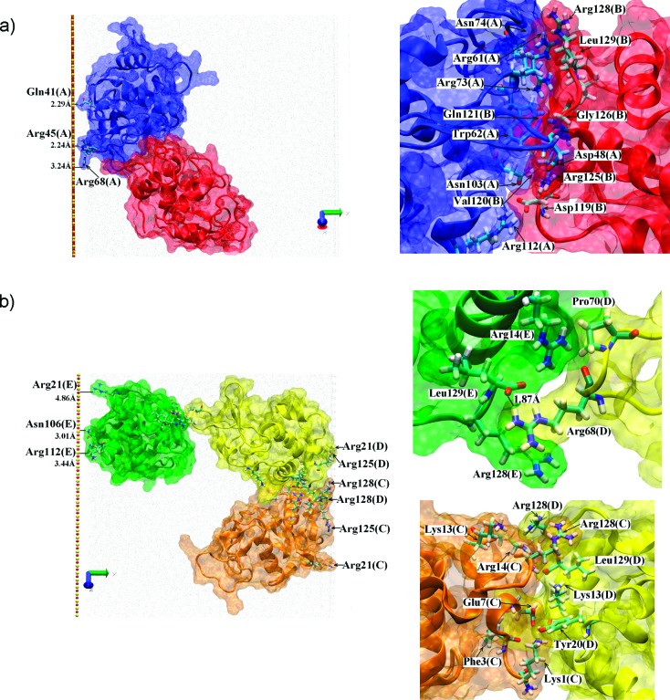
The behavior observed in the simulation with all five proteins in the cell is a composition of the above events as seen in the Supporting Information movies cluster5_1.avi and cluster5_2.avi, which show the trajectory from different view points, and cluster5_3.avi, which shows the situation after 100 ns of the trajectory. Proteins A and B were initially close to each other and created a dimer which then adsorbed as a whole body to the surface using the minor adsorption site of protein A (Figure 5a). For this reason the adsorption is not very strong. Proteins C and D formed a dimer from the start and also adsorbed as a whole body to the image surface, using parts of the N,C-terminal face from both proteins. The CD adsorption, as well as the dimer formation, seems to be relatively strong. Protein E adsorbed as a single protein to the surface and finally found a spatial neighbor, protein D from the CD dimer, which is adsorbed on the image surface at the other side of the simulation cell. Since the ED interface contained only a few residues from both proteins involved and only one H-bond possibility was observed (see Figure 5b and Table 1), this interaction may be described as weak and probably not representative of how proteins interact either on the same surface or freely diffusing in solution.
Figure 5.
Final orientation of the five proteins system. To keep the figure clear and informative, at most three molecules are shown simultaneously. The coloring scheme is the same as in the previous figures. (a) The final orientation of proteins A (blue) and B (red), the inset showing the dimer interface. (b) The final orientation of proteins C (orange), D (yellow), and E (green). Insets show the dimer interfaces DE and CD. Relative orientation of all five molecules may be seen from the cluster5_3.avi file in the Supporting Information.
The interface of the CD dimer in the five-protein simulation is only slightly different to that described above in the two-protein section; Arg128 interacted with both the surface and the partner protein (Figure 5b). Since both proteins also used Arg125 to interact with the surface, the surface adsorption via the N,C-terminal faces remains strong.
The AB dimer interface is very different to the CD one, involving Arg112, Asn103, Asn74, Arg73, Trp62, Arg61, and Asp48 from protein A and Leu129, Arg128, Arg125, Gly126, Gln121, Val120, and Asp119 from protein B (for more details see Table 1 and Figure 5). Due to the spatial locations (on the protein surface) of the various residues we have observed to be involved in dimer interfaces, we speculate that HEWL has at least three areas which may be involved in dimer formation (Figure 6). This has important implications for the type of HEWL aggregate that can form at the surface.
Figure 6.
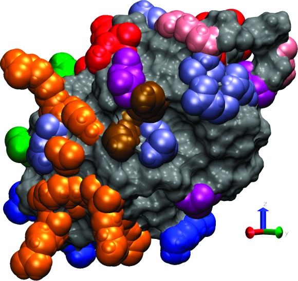
HEWL binding sites and polar residues observed on the protein surface. The protein surface is shown as a solid surface, with the residues composing the main surface adsorption site (Arg128, Arg125, Arg5, Arg14 and Lys1) shown as blue van der Waals spheres. The first (Arg112, Asn103, Arg61, and Asp48), second (Leu129, Arg128, Arg21, Tyr20, Asp18, Arg14, Lys13, and Glu7), and third (Asp119 and Lys116) protein binding sites are indicated by red, orange, and green van der Waals spheres, respectively. Note that residues Arg128 and Arg14 belong to both the main surface adsorption site (the N,C-terminal face) and the second protein binding site. The additional residues are colored as follows: arginines (Arg) pink, aspartic acid (Asp) purple, asparagine (Asn) navy, and lysine (Lys) brown.
The proteins’ dipole moments were always oriented toward the adsorption surface, with the orientation varying from side-on (proteins A and E) to intermediate between side-on and end-on (C and D). Protein B was not adsorbed directly. The main (N,C-terminal face) adsorption site was used by two proteins (C and D), the minor adsorption site (Arg68) by A and the last protein (E) used Arg21 and its spatial neighbors: Arg112, Lys116, and Asn106; details of the adsorbed state of the proteins are shown in Figure 5. In the two later cases adsorption was relatively weak and the proteins were observed to be relatively mobile on the surface, much more than observed for the adsorption via the main adsorption site.4,7
We finish this section by describing the impacts point mutations had on the interactions, targeting Arg128 and Arg68 which we know to be key for single protein surface adsorption.4 Mutations were performed on all five proteins at the final state of the 100 ns trajectory described above. Subsequently a further 100 ns simulation was performed to observe the impact of these mutations. Changing Arg128 to Gly128 weakened the CD dimer interface and reduced the number of residues involved. Only 2 H-bonds were observed after the 100 ns trajectory: Glu7(C)OE2-Lys13(D)HZ2 (1.60 Å) and Asp87(C)OD2-Arg14(D)HH11 (1.65 Å). The new dimer interface comprised Glu7(C), Asp87(C), Lys1(C), Lys13(D), Arg14(D), and Asp18(D). In another, statistically independent trajectory, 100 ns after the mutation no H-bonding was observed and the interface was composed from Phe3(C), Agr14(C), Hsd15(C), Lys13(D), Arg14(D), and Leu129(D). Additionally the mutation of Arg128 had a small but visible influence on the adsorption state; without this residue the adsorption of some proteins appeared weaker. Nevertheless this last effect was not so clear as in the case of systems with lower protein concentration.4 Mutating Arg68 to Gly68 in addition to using Gly128, we find that the weak DE interface is destroyed, causing loss of all contacts between these proteins.
Cluster Formation Mechanisms
To the best of our knowledge, detailed HEWL cluster formation mechanisms have not been previously studied. Based on the protein contacts at the dimer interfaces (see Table 1) and the spatial location on the protein surface of the residues involved in the contacts, we propose that HEWL possesses three regions which may be significant for protein–protein interactions (see Figure 6 and Supporting Information movie binding_sites.avi). The first one (colored red in Figure 6) is composed from Arg112, Asn103, Arg61, and Asp48, and the second one (orange in Figure 6) contains Leu129, Arg128, Arg21, Tyr20, Asp18, Arg14, Lys13, and Glu7. The third region is more speculative; it is made by Asp119 and Lys116 (green in Figure 6) which are capable of forming H-bonds, although we did not observe the conditions for such bonding in our simulations but did find other aspartic acid and lysine residues involved in the protein–protein interface. Note that the second protein binding site lies spatially close to the main adsorption binding site at the N,C terminal face comprising Arg128, Arg125, Arg5, and Lys1 and sometimes Arg144 and can even contain two of its residues (Arg128 and Arg14).
While we have identified three protein–protein binding sites, we note that perhaps more are feasible. In Figure 6 we also show the distribution of polarizable residues across the HEWL surface, all of which might contribute to interprotein binding, although specific competition with intraprotein stabilization would need to be considered first to confirm this. Nevertheless, even with just the three sites observed in our simulations, HEWL might easily form globular-like oligomers on the solid surface due to its “hard protein” surface flexibility, as observed in AFM experiments.14−16 Depending on the local protein concentration, the oligomers may be created in close proximity to the surface as well as in the bulk solution. The main adsorption binding site can be, but does not have to be, exposed to the surface. Due to protein flexibility, the N,C-terminal face can be buried in the dimer interface, or partially or even fully exposed.
Stable dimer formation in bulk water employs more residues than surface adsorption, hence one can speculate that dissociation of preformed dimers (utilizing the N,C terminal face) is more difficult than desorption of strongly adsorbed HEWL from the surface. Indeed, we have previously observed single protein desorption following mutation of Arg128 to a glycine,4 whereas here we did not observe bulk-water dimer dissociation with this mutation. As a consequence, we propose the following multiprotein adsorption mechanisms, depending on local protein concentration.
If the concentration is low, proteins adsorb as monomers using mainly their N,C-terminal face and then diffuse on the surface to create oligomers using the various protein–protein binding sites. If the protein adsorbs using the minor adsorption site (Arg68), desorption is probable as we have seen previously4 and the protein may adsorb again using the preferred and energetically lower main adsorption site. Once a dimer is created, dissociation is not likely and desorption from the surface is also less probable because of the more numerous interactions with the surface. Generally, in a dimer in which both proteins have adsorbed to the surface via the N,C-terminal face, the number of interactions with the surface is double that of a single protein. It is also likely that the surface mobility of dimers will be correspondingly lower than that of single monomers, although we cannot access the time scales for such diffusion in these simulations. Certainly this view is consistent with the experimental AFM data that show surface mobility decreases with cluster size. Larger clusters will then form through the diffusion of the surface-adsorbed species. Note that all our data point to the creation of monolayer clusters on the surface at low protein concentration, in full agreement with the AFM experiments.14−16
In the case of high protein concentration HEWL creates dimers, and possibly higher oligomers, in solution which may affect the accessibility of the main adsorption site. The oligomers then adsorb specifically via the main adsorption site or nonspecifically using any available partially charged residue with a long and flexible side chain. In the first case the adsorption is stable and the oligomers can take a part in the cluster growth process as described above. In the second case the adsorption state is not stable and desorption is very likely. It is possible that the desorbed oligomers might then change their internal organization to be available for subsequent specific adsorption, although this process might be kinetically limited.
Conclusions
We have found that HEWL possesses at least three regions which can be involved in the dimer interface so that higher order oligomerization, both in solution and on the surface, is possible. The categorization of HEWL as a hard protein, which maintains its tertiary and secondary structures well while possessing surface flexibility, is fully endorsed by our simulations and supports the conclusion for oligomer formation.
We have found that while there is competition between dimer formation and surface adsorption, one does not preclude the other. We can therefore anticipate the growth of monolayer clusters on the charged ionic solid surface when exposed to a dilute solution of HEWL, as indeed is observed experimentally.14−16 In this regard, the study has been successful in elucidating molecular-level details of larger-scale film formation mechanisms. However, as with all computational studies, we must bear in mind the limitations of the methodology. The choice of force field parameters, and the short duration of the simulated time compared to experiment, are common considerations when interpreting simulation. In this study we also must acknowledge that we have created a very crowded system in a limited cell size, so that sometimes the protein clusters can interact with themselves and with image surfaces due to the periodic boundary conditions employed. Throughout our discussion we have tried not to overinterpret any artifacts that these conditions induce, such as when the CD dimer interacts with the image surface and the E protein then interacts with the surface as well as the CD pair (five proteins system). Instead we focus on the type of interface that can form during protein–protein and protein–surface interactions, bearing in mind the limitations of the methodology we have employed, and believe that we have successfully gained important insights that cannot be obtained in any other way.
Given the growing importance of biotechnologies which depend on a detailed understanding of the nature of protein film formation,23 we believe this type of simulation has an important role to play in future research. We have demonstrated that it is possible to gain insight into the earliest stages of protein aggregation at a surface, and believe the same approach will provide essential guidance to a wide range of technologically relevant systems.
Acknowledgments
This work was supported by the U.K. Engineering and Physical Sciences Research Council through Grant No. EP/E013384 and by University of Strathclyde. Parts of our results were obtained using the National Service for Computational Chemistry Software (NSCCS) resources (URL: http://www. nsccs.ac.uk) and the Faculty of Engineering High Performance Computer at the University of Strathclyde.
Supporting Information Available
Movies showing protein dynamics in illustrative trajectories as well as location of the protein binding sites and the molecular dynamics protocol. This material is available free of charge via the Internet at http://pubs.acs.org.
Supplementary Material
References
- Huebsch N.; Mooney D. J. Nature 2009, 462, 426. [DOI] [PMC free article] [PubMed] [Google Scholar]
- Langer R.; Tirrell D. A. Nature 2004, 428, 487. [DOI] [PubMed] [Google Scholar]
- Peng G.; Tisch U.; Adams O.; Hakim M.; Shehada N.; Broza Y. Y.; Billan S.; Abdah-Bortnyak R.; Kuten A.; Haick H. Nat. Nanotechnol. 2009, 4, 669. [DOI] [PubMed] [Google Scholar]
- Kubiak-Ossowska K.; Mulheran P. A. Langmuir 2010, 26, 15954. [DOI] [PubMed] [Google Scholar]
- Mulheran P. A; Kubiak K. Mol. Simul. 2009, 35, 561. [Google Scholar]
- Kubiak K.; Mulheran P. A. J. Phys. Chem. B 2009, 113, 12189. [DOI] [PubMed] [Google Scholar]
- Kubiak-Ossowska K.; Mulheran P. A. Langmuir 2010, 26, 7690. [DOI] [PMC free article] [PubMed] [Google Scholar]
- Sauter C.; Otalora F.; Gavira J. A.; Vidal O.; Giege R.; Garcia-Ruiz J. M. Acta Crystallogr., Sect. D 2001, 57, 1119. [DOI] [PubMed] [Google Scholar]
- Wertz C. F.; Santore M. M. Langmuir 2002, 18, 1190. [Google Scholar]
- Aizawa T.; Koganesawa N.; Kamakura A.; Masaki K.; Matsuura A.; Nagadome H.; Terada Y.; Kawano K.; Nitta K. FEBS Let. 1998, 422, 175. [DOI] [PubMed] [Google Scholar]
- Ravichandran S.; Madura J. D.; Talbot J. J. Phys. Chem. B 2001, 105, 3610. [Google Scholar]
- Dismer F.; Petzold M.; Hubbuch J. J. Chromatogr. A 2008, 1194, 11. [DOI] [PubMed] [Google Scholar]
- Xie Y.; Zhou J.; Jiang. S. J. Chem. Phys. 2010, 32, 065101. [DOI] [PubMed] [Google Scholar]
- Kim D. T.; Blanch H. W; Radke C. J. Langmuir 2002, 18, 5841. [Google Scholar]
- Mulheran P. A.; Pellenc D.; Bennett R. A.; Green R. J.; Sperrin M. Phys. Rev. Lett. 2008, 100, 068102. [DOI] [PubMed] [Google Scholar]
- Pellenc D.; Bennett R. A.; Green R. J.; Sperrin M; Mulheran P. A. Langmuir 2008, 24, 9648. [DOI] [PubMed] [Google Scholar]
- Bruzzesi M. R.; Chiancone E.; Antonini E. Biochemistry 1965, 4, 1796. [DOI] [PubMed] [Google Scholar]
- Etheve J.; Dejardin P.; Boissiere M. Colloids Surf., B 2003, 28, 285. [Google Scholar]
- Ermakova E. J. Mol. Model 2005, 12, 34. [DOI] [PubMed] [Google Scholar]
- Onuma K.; Inaka K. J. Cryst. Growth 2008, 310, 1174. [Google Scholar]
- Wahlgren M.; Arnebrant T.; Lundström I. J. Colloid Interface Sci. 1995, 175, 506. [Google Scholar]
- Ball V.; Ramsden J. J. J. Colloids Surf., B 2000, 17, 81. [Google Scholar]
- Schmitt Y.; Hahl H.; Gilow C.; Mantz H.; Jacobs K.; Leidinger O.; Bellion M.; Santen L. Biomicorfluidics 2010, 4, 032201. [DOI] [PMC free article] [PubMed] [Google Scholar]
Associated Data
This section collects any data citations, data availability statements, or supplementary materials included in this article.


