Abstract
For biological samples showing a preferred orientation on the carbon support film of an electron microscope (EM) grid, accurate three-dimensional (3D) reconstructions by single-particle cryo-EM require data collection in which the specimen grids are tilted in the microscope, to obtain adequate numbers of particles that cover the high-degree angular distribution. However, image drift caused by the electron beam interacting with the cryo specimen becomes severe when grids are tilted to high angles (> 30°). We produced deformed grids by applying a deliberate mechanical deformation to EM grids containing a thin carbon film supported by a thick holey carbon film. We applied cryo-EM using deformed grids to the isolated cardiac ryanodine receptor, an ion channel complex known to assume a preferred orientation on the carbon support film. These grids contained more particles having high Euler angle orientations without the need to tilt the specimen grids. Meanwhile, the drifting that was apparent in the images was reduced from that typical of images from tilted regular EM grids. This was achieved by imaging particles in holes close to the deformed areas, where carbon films were locally bent, offering planes of inclination with various angles. The deformed grids improve the efficiency and quality of data collection for single-pahrticle cryo-EM of samples showing a limited range of orientations.
Keywords: single-particle cryo-EM, deformed EM grids, preferred orientation, ryanodine receptor
Single-particle methods have been developed that allow three-dimensional (3D) reconstructions to be determined from electron micrographs of isolated macromolecules. Over the past 30 years, this methodology has been applied to numerous biological macromolecules, such as proteins, RNAs, and macromolecular complexes and assemblies (Frank, 2009). When preparing cryo-EM samples, a thin layer of continuous carbon support film is commonly applied over holey carbon EM grids (Grassucci et al., 2007). The thin carbon film improves the sample stability when exposed to the electron beam. In addition, it allows accurate determination of the defocus value from the strong Thon rings in Fourier space. However, some macromolecules have a preferred orientation on the carbon film, and so to compute an accurate 3D reconstruction, specimen grids need to be tilted up to 50-60° in the microscope to obtain particles that adequately cover the high-degree angular distribution, regardless of which reconstruction method (random conical or projection matching) is used (Penczek et al., 1994; Radermacher et al., 1987). Electron crystallography of two-dimensional crystals is another reconstruction technique in 3D cryo-EM that also requires recording images and electron diffraction patterns at a series of tilted angles (up to 70°) (Walz and Grigorieff, 1998).
Unfortunately, tilting the cryo samples enhances the effect of charging, leading to an apparent image drift problem. Charging is the buildup of electric charges on the layer of vitreous ice, which is particularly problematic in the highly tilted (>30°) images, and results in blurry, unusable images (Glaeser and Downing, 2004). Charging causes only a slight change in focus but little or no image drifting in the low-tilt (<20°) images. For example, we find that with our sample of ryanodine receptor (Meng et al., 2009), images of untilted specimen are readily obtained, such that, typically, several hundred CCD images can be acquired in about six hours and over 90% are useable for further image processing. This number can be increased several-fold when automated data acquisition software is adopted (Suloway et al., 2005). On the contrary, when grids are tilted above 30°, based on our experience, less than 20% of the images can be used. Another problem accompanying tilted specimens is reduced contrast in the images, which results from the increased thickness of the ice layer. At 60° tilt, the ice thickness is effectively doubled.
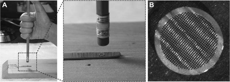
It has been shown that image drifting can be reduced by a superfluid helium-cooled cryo-EM stage (Fujiyoshi et al., 1991), by using titanium-silicon metal glass film (Rhinow and Kühlbrandt, 2008) or doped silicon carbide nanocrystalline film (Yoshioka et al., 2010) instead of carbon film, or applying an additional carbon film to the side of the ice layer facing away from the primary carbon support on the grid (Gyobu et al., 2004). Previously, trimming of the EM grids with a scalpel and bending them with tweezers was briefly mentioned by Kühlbrandt and Unwin, and by Deatherage and colleagues as an aid to achieve high tilt angles (Deatherage et al., 1983; Kühlbrandt and Unwin, 1982). However, the samples were either glucose-embedded or negatively stained for conventional EM, but not frozen-hydrated for cryo-EM. To improve the quality of cryo-EM images and efficiency of data collection, we are seeking an alternative and simple approach to obtain high angular distributions of biological macromolecules that have a preferred orientation on the carbon film, without the need to tilt the specimen grids. This is achieved by creating some small areas with locally tilted carbon support films by mechanically deforming (wrinkling) the EM grids, followed by adding sample solution to the grids, blotting, and plunging into liquid ethane as in typical procedures (Grassucci et al., 2007). Since the wrinkled carbon support films are formed before the macromolecules become embedded in the ice layer, the thickness of the ice layer in the locally tilted carbon support films is similar to the ice layer on those areas of the grid where carbon support film is flat. Moreover, particles with high Euler angles can be imaged in these locally tilted carbon films. The procedure to produce deformed EM grids is straightforward. We have made a mold that has ridges from an inner surface of a tweezers tip. A pencil eraser (clean and flat) is used as a pressure plate. A deformed grid is produced by pressing the pencil eraser on the EM grid, which is place over the mold, as shown in Figure 1.
Figure 1. Set-up for producing deformed EM grid.
(A). A mold is made from a tweezers tip, and a holey EM grid with a thin layer of carbon support film is placed on the surface with ridges. A pencil eraser is used as a stamping tool. A deformed grid is produced by applying pressure on the EM grid. (B) Picture of a deformed EM grid taken on an Olympus dissecting microscope showing a wrinkled surface.
We were very cautious when blotting the grids to avoid the possibility of flattening the locally deformed areas of the grids. We have tried: (1) blotting from the edge of the grids with a torn edge of filter paper so as to avoid applying any pressure directly on the deformed grids; (2) double-sided blotting using a homemade guillotine plunger with two soft cushion pads layered underneath filter papers; (3) double-sided blotting using a Gatan CP3 semi-automatic plunger with GentleBlot Technology (GentleBlot optimizes blotting force by mean of adjustable blotting pressure for gentle and effective blotting), and we used the lowest blotting pressure to avoid flattening the deformed grids. Nevertheless, methods (2) and (3) still resulting in some flattening, but the results were more reproducible compared to method (1). Results shown below are mainly from the cryo deformed grids prepared with the Gatan CP3 plunger. Roughly, we can find intact holey films in ~30% local highly tilted areas.
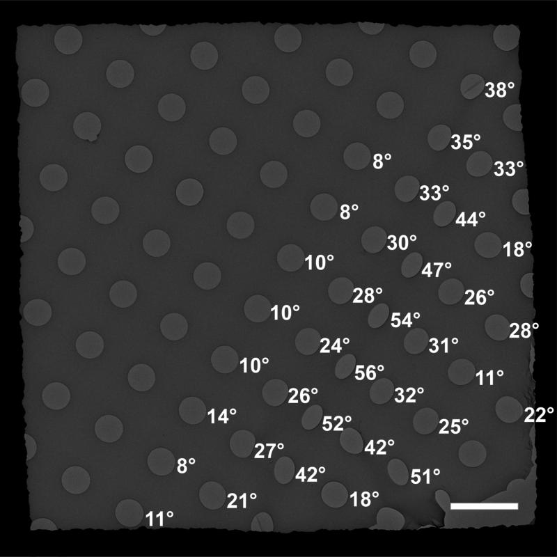
Quantifoil grids (type 2/4 which have ~2 μm circular holes and a spacing of ~4 μm between the holes) were used to test for the presence of locally tilted carbon films: the holes in the flat regions are circular in shape, whereas those from the wrinkled areas appear elliptical and the local tilting angles can be determined from the ratio of the transverse and conjugate diameters of the ellipses. We found that the majority of holes showed small changes in shape, corresponding to tilting angles below 20°, but some areas had holes that tilted up to 60° (Figure 2). For images recorded in the holes with locally tilted carbon films, image drifting was not completely eliminated but the fraction of usable images was improved. In certain grids, 90% of CCD images were suitable for further analysis. We agree with others that beam-induced movement due to charging is likely to be a major source of image degradation for cryo-specimens, especially at high tilt angles (Downing et al., 2004; Glaeser and Downing, 2004; Yoshioka et al., 2010). However, other factors, such as tilting of the side-entry cryo-holder in the stage, can also introduce instability of the specimen and result in image drifting. Using the deformed grids to avoid tilting the holder will completely eliminate the image drifting cause by instability of the tilted cryo holder. The reason for deformed grids improvement is not fully clear and needs further investigation, for example, measuring the ice thickness in the locally tilted holes and in the untilted holes, measuring the success rates in the locally low tilted holes and in locally high tilted holes. Nonetheless, it showed that deformed grids could reduce image drifting and improve the success rate in data collection of tilted images.
Figure 2. Deformed EM grids have locally tilted carbon support films.
A CCD image of a deformed Quantifoil grid captured on a FEI Tecnai F20 electron microscope, showing that some of the circular holes appear elliptical due to localized tilting of the carbon film. Numbers next to the holes are the local tilt angles determined from the ratio of the transverse and conjugate diameters of the ellipses. Scale bar = 5 μm.
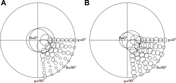
We collected two cryo-EM datasets of cardiac ryanodine receptor (RyR2) (Liu et al., 2002), one using regular EM grids, and the other one use deformed EM grids. Both datasets were imaged without tilting the specimen grids in the cryo-holder, and for deformed grids, images were recorded in the holes with locally untilted or tilted carbon films. 3,756 and 3,573 particles were selected from regular EM grids and deformed EM grids, respectively. Particles from both datasets were aligned to a set of reference projections that were generated from a reference 3D volume. Since the RyR2 is a rotationally symmetric homo-tetramer, 4-fold symmetry is usually applied in the image processing, and so the range of the angle ϕ only needs to be between 0° and 90°, and thus the Euler angular distribution only covers one quarter of the 3D sphere. The angular step of angle θ was set to 10° in this test, which resulted in 48 projection directions that were quasi-evenly spaced over one quarter of the 3D sphere.
Figure 3 shows the angular distribution of aligned particles from the two datasets. The diameters of the circles indicate the relative numbers of particles. Particles are clearly distributed more toward higher Euler angles (≥ 30°) in the deformed grids compared to the regular EM grids. The RyR2 has a preferred orientation on the carbon support film with more than 70% of particles having orientations with Euler angles less than 30°, and only ~30% of the particles have orientation ≥ 30° (Figure 3A). In contrast to regular EM grids, the number of particles in each high angular direction (30°-90°) almost doubled for the deformed EM grids, over 56% of the particles having an orientation with an Euler angles ≥ 30° (Figure 3B).
Figure 3. Deformed EM grids increased frequency of particles displaying high Euler angles.
Plots of the Euler angle distribution of RyR2 particle orientations on regular holey EM grids (A) and on deformed EM grids (B), particles (3,756 particles from regular grids, and 3,573 from deformed grids) are from images that were collected without tilting the specimen grids in the microscope. Since the RyR2 is a homo-tetramer, 4-fold symmetry is usually applied during image processing, and so the Euler angle distribution only covers one quarter of the 3D sphere. The diameters of the circles indicate the relative numbers of particles. More particles are distributed toward high Euler angles (≥ 30°) in the deformed grids than in the regular EM grids.
To verify the quality of the particles in the deformed grids, we computed a 3D reconstruction of RyR2 using the Spider/WEB software package (Frank et al., 1996). We expanded the dataset to a total number of 9,189 particles, and a 3D reconstruction of RyR2 was computed from 7,155 particles (some particles with lower Euler angles were removed to ensure that each view would be represented by almost equal numbers of particles). The resolution, 30 Å, was measured by using the Fourier shell correlation criteria with a cutoff of 0.5 (Malhotra et al., 1998). For comparison, the same resolution was attained for our recent published 3D reconstruction of RyR2 (Huang et al., 2012), which was computed from 7,102 particles, selected from a dataset of 23,566 particles so as to achieve roughly equal sampling of the views. The images were collected with regular cryo-EM grids tilted in specimen holder at 0°, 10°, 20°, 30°, 40°, and 50°. These results demonstrated that particles from deformed grids and from regular grids are of similar quality, but the efficiency of data collection using untilted deformed grids was improved. In addition, use of deformed grids avoids oversampling of particles with lower Euler angles that results from using regular grids.
In summary, we describe here a simple novel method to remodel EM grids by applying a deliberate mechanical deformation using a simple homemade device. The deformed EM grids can be used in cryo-EM data collection for biological samples that have a preferred orientation on the carbon support film. Particles with high angular distributions are readily obtained without tilting the specimen grids, and the image drifting is greatly reduced relative to that which is typically present when regular EM grids are tilted.
Acknowledgments
We gratefully acknowledge the 3D-EM Facilities at the Wadsworth Center. This work was supported by National Institutes of Health grants R01HL095541 and R01AR040615.
Footnotes
Publisher's Disclaimer: This is a PDF file of an unedited manuscript that has been accepted for publication. As a service to our customers we are providing this early version of the manuscript. The manuscript will undergo copyediting, typesetting, and review of the resulting proof before it is published in its final citable form. Please note that during the production process errors may be discovered which could affect the content, and all legal disclaimers that apply to the journal pertain.
References
- Deatherage JF, Taylor KA, Amos LA. Three-dimensional arrangement of the cell wall protein of Sulfolobus acidocaldarius. J. Mol. Biol. 1983;167:823–848. doi: 10.1016/s0022-2836(83)80113-2. [DOI] [PubMed] [Google Scholar]
- Downing KH, McCartney MR, Glaeser RM. Experimental characterization and mitigation of specimen charging on thin films with one conducting layer. Microsc. Microanal. 2004;10:783–789. doi: 10.1017/s143192760404067x. [DOI] [PubMed] [Google Scholar]
- Frank J. Single-particle reconstruction of biological macromolecules in electron microscopy – 30 years. Q. Rev. Biophys. 2009;42:139–158. doi: 10.1017/S0033583509990059. [DOI] [PMC free article] [PubMed] [Google Scholar]
- Frank J, Radermacher M, Penczek P, Zhu J, Li Y, Ladjadj M, Leith A. SPIDER and WEB: Processing and visualization of images in 3D electron microscopy and related fields. J. Struct. Biol. 1996;116:190–199. doi: 10.1006/jsbi.1996.0030. [DOI] [PubMed] [Google Scholar]
- Fujiyoshi Y, Mizusaki T, Morikawa K, Yamagishi H, Aoki Y, Kihara H, Harada Y. Development of a superfluid helium stage for high-resolution electron microscopy. Ultramicroscopy. 1991;38:241–251. [Google Scholar]
- Glaeser RM, Downing KH. Specimen charging on thin films with one conducting layer: Discussion of physical principles. Microsc. Microanal. 2004;10:790–796. doi: 10.1017/s1431927604040668. [DOI] [PubMed] [Google Scholar]
- Grassucci RA, Taylor DJ, Frank J. Preparation of macromolecular complexes for cryo-electron microscopy. Nat. Protoc. 2007;2:3239–3246. doi: 10.1038/nprot.2007.452. [DOI] [PMC free article] [PubMed] [Google Scholar]
- Gyobu N, Tani K, Hiroaki Y, Kamegawa A, Mitsuoka K, Fujiyoshi Y. Improved specimen preparation for cryo-electron microscopy using a symmetric carbon sandwich technique. J. Struct. Biol. 2004;146:325–333. doi: 10.1016/j.jsb.2004.01.012. [DOI] [PubMed] [Google Scholar]
- Huang X, Fruen B, Farrington DT, Wagenknecht T, Liu Z. Calmodulin-binding locations on the skeletal and cardiac ryanodine receptors. J. Biol. Chem. 2012;287:30328–30335. doi: 10.1074/jbc.M112.383109. [DOI] [PMC free article] [PubMed] [Google Scholar]
- Kühlbrandt W, Unwin PNT. Distribution of RNA and protein in crystalline eukaryotic ribosomes. J. Mol. Biol. 1982;156:431–448. doi: 10.1016/0022-2836(82)90259-5. [DOI] [PubMed] [Google Scholar]
- Liu Z, Zhang J, Li P, Chen SRW, Wagenknecht T. Three-dimensional reconstruction of the recombinant type 2 ryanodine receptor and localization of its divergent region 1. J. Biol. Chem. 2002;277:46712–46719. doi: 10.1074/jbc.M208124200. [DOI] [PubMed] [Google Scholar]
- Malhotra A, Penczek P, Agrawal RK, Gabashvili IS, Grassucci RA, Jünemann R, Burkhardt N, Nierhaus KH, Frank J. Escherichia coli 70 S ribosome at 15 Å resolution by cryo-electron microscopy: localization of fmet-tRNAfMet and fitting of L1 protein. J. Mol. Biol. 1998;280:103–116. doi: 10.1006/jmbi.1998.1859. [DOI] [PubMed] [Google Scholar]
- Meng X, Wang G, Viero C, Wang Q, Mi W, Su X-D, Wagenknecht T, Williams AJ, Liu Z, Yin C-C. CLIC2-RyR1 interaction and structural characterization by cryo-electron microscopy. J. Mol. Biol. 2009;387:320–334. doi: 10.1016/j.jmb.2009.01.059. [DOI] [PMC free article] [PubMed] [Google Scholar]
- Penczek PA, Grassucci RA, Frank J. The ribosome at improved resolution: New techniques for merging and orientation refinement in 3D cryo-electron microscopy of biological particles. Ultramicroscopy. 1994;53:251–270. doi: 10.1016/0304-3991(94)90038-8. [DOI] [PubMed] [Google Scholar]
- Radermacher M, Wagenknecht T, Verschoor A, Frank J. Three-dimensional reconstruction from a single-exposure, random conical tilt series applied to the 50S ribosomal subunit of Escherichia coli. J. Microsc. 1987;146:113–136. doi: 10.1111/j.1365-2818.1987.tb01333.x. [DOI] [PubMed] [Google Scholar]
- Rhinow D, Kühlbrandt W. Electron cryo-microscopy of biological specimens on conductive titanium–silicon metal glass films. Ultramicroscopy. 2008;108:698–705. doi: 10.1016/j.ultramic.2007.11.005. [DOI] [PubMed] [Google Scholar]
- Suloway C, Pulokas J, Fellmann D, Cheng A, Guerra F, Quispe J, Stagg S, Potter CS, Carragher B. Automated molecular microscopy: The new Leginon system. J. Struct. Biol. 2005;151:41–60. doi: 10.1016/j.jsb.2005.03.010. [DOI] [PubMed] [Google Scholar]
- Walz T, Grigorieff N. Electron crystallography of two-dimensional crystals of membrane proteins. J. Struct. Biol. 1998;121:142–161. doi: 10.1006/jsbi.1998.3945. [DOI] [PubMed] [Google Scholar]
- Yoshioka C, Carragher B, Potter CS. Cryomesh™: A new substrate for cryo-electron microscopy. Microsc. Microanal. 2010;16:43–53. doi: 10.1017/S1431927609991310. [DOI] [PMC free article] [PubMed] [Google Scholar]


