Abstract
Objective:
Tooth/implant supported fixed prostheses may present biomechanical design problems, as the implant is rigidly anchored within the alveolus, whereas the tooth is attached by the periodontal ligament to the bone allowing movement. Many clinicians prefer tooth/implant supported fixed prosthesis designs with rigid connectors. However, there are some doubts about the effect of attachment placement in different prosthesis designs. The purpose of this study was to examine the stresses accumulated around the implant and natural teeth under occlusal forces using three dimensional finite element analysis (3D FEA).
Materials and Methods:
In this study, different connection designs of tooth/implant fixed prosthesis in distal extension situations were investigated by 3D FEA. Three models with various connection designs were studied; in the first model an implant rigidly connected to an abutment, in the second and third models an implant connected to abutment tooth with nonrigid connector in the distal part of the tooth and mesial part of the implant. In each model, a screw type implant (5×11mm) and a mandibular second premolar were used. The stress values of these models loaded with vertical forces (250N) were analyzed.
Results:
There was no difference in stress distribution around the bone support of the implant. Maximum stress values were observed at the crestal bone of the implant. In all models, tooth movement was higher than implant movement.
Conclusion:
There is no difference in using a rigid connector, non rigid connector in the distal surface of the tooth or in the mesial surface of an implant.
Keywords: 3D Finite Element Analysis, Fixed Prosthesis, Rigid Connection, Non- Rigid Connection
INTRODUCTION
Dental implant has been accepted as a successful clinical reality due to osseointegration. Despite the fact that dental implants have been used widely for restoring complete and partial edentulous jaws, still there is debate on connecting the implant to the natural tooth [1].
Having used implant in fixed partial denture, fixed prostheses can be supported either by implant or tooth/implant (tooth/implant supported fixed prostheses [TIFPs]).
According to Branemark protocol in partially edentulous dentition taking into account the differential reaction of the implant and natural tooth in static and dynamic load, the connection of the natural tooth to the implant is avoided [2]. Since there is a biomechanical challenge in connecting teeth to osseointegrated implants, the use of rigid connectors (RCs) in TIFPs is not supported by Skalak [3,4]. Implants being rigidly fixed to the bone differ from natural teeth surrounded by periodontal ligaments in terms of viscoelastic properties. Consequently, under masticatory load, different patterns of stress and strain can be seen in the bone around the implant and the tooth [5–8]. Besides, the stress and strain pattern on natural teeth and the surrounding structures, which healthy periodontal ligament allows a mobility of 50 to 200 μm to the natural teeth and the flexibility of the bone may allow 10 μm implant movement [6]. The other criterion is that no lateral force should be designed on the prosthesis.
To compensate for dissimilar mobility of natural teeth and implant systems, several specific methods have been suggested.
Non rigid connectors (NRCs) act as stress breakers with the ability to separate the splinted units [8,14], an implant with a stress-absorbing element (intra mobile element or stress-breaking element) or an implant with a stress-eliminating space have been recommended by some authors for TIFPs [6,15,20].
However, several reports have explored the use of non-rigid connectors and the association with abutment tooth intrusion [16,17].
Theoretically, the tooth intrusion phenomenon could be the consequence of disuse atrophy, mechanical binding and weakened rebound memory.
On the other hand, thanks to prosthesis and implant, rigid connectors have the inherent flexibility to modify dissimilar mobility characteristics [18].
Although the long-term radiographic evaluation of TIFPs is in favor of non-rigid connectors for less bone loss around the implant in comparison with rigid connectors[18,19], there is no agreement on proper connector’s design selection for TIFPs systems.
The outcome of in vitro studies has shown unequal force distribution which is not usually compatible with the observed results in in vivo studies [20–23, 28–33].
MATERIALS AND METHODS
The review of the literature reveals that consensus regarding the use of RCs, NRCs or stress-absorbing element has not been achieved. Besides, there is no detailed assessment of the role and location of NRCs between the natural tooth and implant [24–27, 34]. In this in vitro study, our null hypothesis was that various connection designs in the TIFPs may not change the load transfer between the implant and tooth abutments. Therefore, the purpose of this study was to examine the stress distribution on the supporting structures of the TIFPs under static vertical loads with the 3D FEA. In this study, three types of different TIFP designs in the distal extension partially edentulous mandible were evaluated. It was assumed that the first and second molars were extracted and an implant was inserted in the second molar position. Computer tomography (CT) images of an adult human mandible was used to make the three dimensional model of the edentulous mandible distal to the second premolar [35–37].
CT data in DICOM format was imported into the software of Rapid Form (INUS Technology, Seoul, Korea).
In this software, the CT data were directly converted to surface and finally the solid model. The height of the posterior mandibular region was determined as 23mm, the cortical bone thickness was determined as 2mm and the periodontal membrane width was accepted as 0.25mm [38].
For the solid-model construction of these prostheses, three extracted intact teeth (second premolar, first and second molars) and an implant fixture (Biomet 3i, 5×11) were used.
They were digitized using the optical digitizing system ATOS II (GOM, Braunschweig, Germany) [39,41].
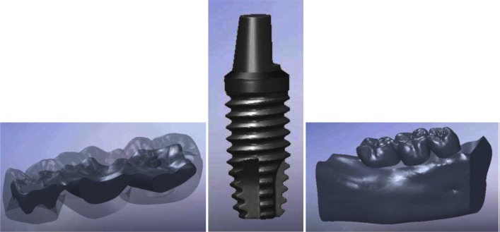
This system digitizes the objects with high accuracy and 3D local. The measured data can be exported as point clouds, sections or STL-data. Here, STL-data imported to Rapid Form (INUS Technology, Seoul, Korea) was used to make the solid models of the teeth and implant system (Fig 1) [41–,43].
Fig 1.
The prepared 3D solid model, A) the 3-unit FP, B) the implant system, C) the assembled model consisting of tooth (second premolar), PDL, the implant system, the 3-unit FP, and alveolar bone.
Then the models of the pulp and the simplified 0.25mm periodontal ligament (PDL) of the second premolar were obtained as reference from Wheeler`s measurements [38]. The axes of the natural teeth and the implants in the models were compatible with the Spee Curve. In addition, the prepared models of the teeth were used to construct a 3-unit FPD in Solid Works 2008 environment [42].
In this design of the prosthesis, the thickness of porcelain was 1.5 to 2mm and gold alloy was used as a metal substructure material (Table 1) [44]. Finally, all these prepared models were assembled. Three models consisted of:
Model 1: The second premolar and the implant were connected rigidly.
Model 2: The second premolar and the implant were connected by a non-rigid attachment with the matrix connector positioned on the distal side of the second premolar.
Model 3: The second premolar and the implant were connected by a non-rigid attachment with the matrix connector positioned on the mesial side of the implant (Table 2).
Table 1.
Mechanical properties of the Materials
| Material | Young (Elastic)’s Modulus(MPa) | Poisson’s Ratio |
|---|---|---|
| Cortical bone | 13700 | 0.30 |
| Cancellous bone | 1370 | 0.30 |
| Titanium (implant system) | 103400 | 0.35 |
| Gold alloy | 100000 | 0.30 |
| Porcelain | 69000 | 0.28 |
| Dentin | 18600 | 0.31 |
| Pulp | 3 | 0.45 |
| Periodontal ligament | 69 | 0.45 |
Table 2.
Fixed Prosthesis Designs Used in this Study
| Fixed prosthesis design | |
|---|---|
| Model 1 | The second and the implant are connected rigidly |
| Model 2 | The second premolar and the implant are connected by a nonrigid attachment with the matrix connector positioned on the distal side of the premolar |
| Model 3 | The second premolar and the implant are connected by a non-rigid attachment with the matrix connector positioned on the mesial side of the implant |
When a rigid connector was used in the FE models, the nodes attached to the patrix/matrix components at the same location needed to merge to modify the original interfacial fixation (contact), becoming a bonded condition.
This did not allow relative micro-motion and the displacement was continuous between the different materials.
In this study, mesh generation and data processing were carried out in the 3D FEM analysis package (ABAQUS V6.7-1; Simulia Corp., Providence, USA). The mesh consisted of the 4-node linear tetrahedral solid elements with an approximate element size of 0.3mm (300μm) to obtain more accurate results [38].
The entire model included 911,449 elements and 1,196,657 nodes.
Materials used in this study were evaluated as homogenous, isotropic and linear and the osseointegration of the implants was accepted as 100% [26]. In the mathematical model, while the implants were directly in contact with the bone, the natural teeth had primary mobility within the borders of the periodontal membrane. Besides, the matrix and the patrix surfaces of the NRC of the TIFP were allowed to vertically move on each other. The nodes at the mesial and distal surfaces of the alveolar bone were fixed in all directions as the boundary condition. Contact between the patrix and matrix surfaces of the nonrigid connectors was assigned as tangential-frictionless (non bonded), to simulate the sliding function of a nonrigid connector; whereas the other parts of the model were assumed to be completely tied to each other. A linear static analysis was performed on the prepared 3D solid models with a vertical occlusal load of 250 N on the occlusal surface of each tooth at a right angle (0° to the long axis of supports) on the central fossa.
RESULT
Stress at Bone Regions
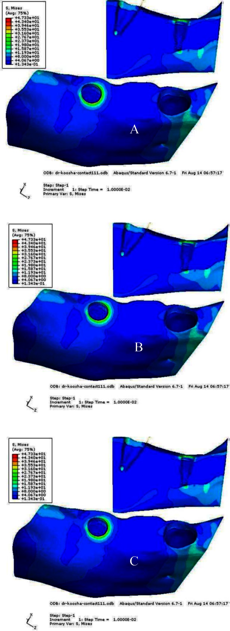
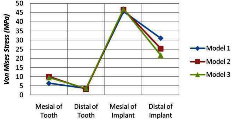
The patterns of stress distribution in all three models were almost similar, but the differences were in the stress values. The maximum stress values in the mesial and distal surfaces of the crestal region of the implant bone interface was 45.62 and 31.05 MPa, respectively. The maximum stress values accumulated around the natural tooth were 6.47 MPa in the mesial and 3.68 MPa in the distal crestal surface. The equivalent Von Mises stress contours for the rigid connection configuration are shown in Figure 2A.
Fig 2.
The equivalent Von Mises stress contours, A) model 1, B) model 2, C) model 3
Model 2 (The second premolar and the implant are connected by a non-rigid attachment with the matrix connector positioned in the distal side of the second premolar):
The highest equivalent Von Mises stress values were obtained in the cortical bone region of both mesial and distal sides with values ranging between 46.69 and 25.38 MPa, respectively. The maximum stresses around the natural tooth were 10.10 MPa and 3.29 MPa in mesial and distal crestal region, respectively.
The Von Mises stress contours for Model 2 are shown in Figure 2B.
Model 3 (The second premolar and the implant are connected by a non-rigid attachment with the matrix connector positioned on the mesial side of the implant): The highest equivalent Von Mises stress values were 46.98 and 21.78 MPa, respectively in the mesial and distal cortical region of the implant abutment. The stresses around the natural tooth were 9.64 and 3.67 MPa in the mesial and distal cortical region, respectively. The equivalent Von Mises stress contours for Model 3 are shown in Figure 2C. Maximum equivalent Von Mises stress values in selected critical regions of the models are summarized in Table 3.
Table 3.
Von Mises Stresses at Critical Regions (MPa)
| Around Natural Tooth (MPa) | Around Implant Abutment(MPa) | |||
|---|---|---|---|---|
| Mesial | Distal | Mesial | Distal | |
| Model 1 | 6.47 | 3.68 | 45.62 | 31.05 |
| Model 2 | 10.10 | 3.29 | 46.69 | 25.38 |
| Model 3 | 9.64 | 3.67 | 46.98 | 21.78 |
Stress at the Implant System
There was no significant difference in the patterns of Von Mises stress distribution in implant system of all three models.
But, the values of stress were different in each model.
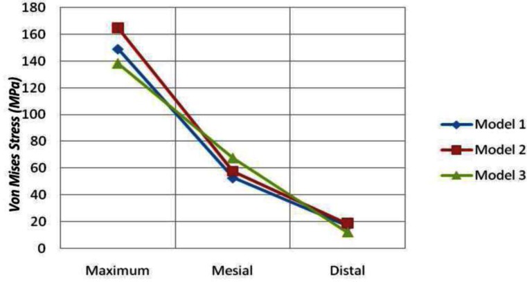
Model 1: The maximum stress value on the implant was 149.1 MPa. The maximum stresses in mesial and distal side of the implant were 52.74 and 16.88 MPa, respectively. The Von Mises stress contours of the implant for Model 1 are shown in Figure 3.
Fig 3.
The Vone Mises stress contours of the implant, A) model 1, B) model 2, C) model 3
Model 2: The highest Von Mises stress was 165.0 MPa for the implant system.
The maximum Von Mises stresses were 57.66 and 18.70 MPa in the mesial and distal of the implant, respectively. The Von Mises stress contours of the implant for Model 2 are shown in Figure 3.
Model 3: The highest equivalent Von Mises stress value was 138.3 MPa in the implant.
The maximum Von Mises stresses accumulated in the mesial and distal side of the implant were 67.59 and 12.17 MPa, respectively.
The Von Mises stress contours of the implant for Model 3 are shown in Figure 3. The maximum equivalent Von Mises stress values in all three models are summarized in Table 4.
Table 4.
Von Mises Stresses at the Implant System (MPa)
| Maximum (MPa) | Mesial (MPa) | Distal (MPa) | |
|---|---|---|---|
| Model 1 | 149.1 | 52.74 | 16.88 |
| Model 2 | 165.0 | 57.66 | 18.70 |
| Model 3 | 138.3 | 67.59 | 12.17 |
Displacement of the tooth and the Implant
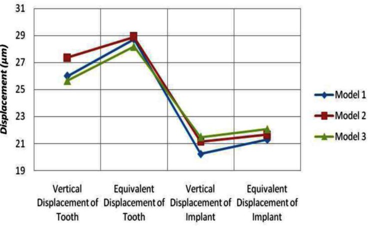
Model 1: The maximum vertical displacements of the natural tooth and the implant were 26.01 and 20.24 μm, respectively. In addition, the maximum equivalent displacement was 28.74 μm for the natural tooth and 21.30 μm for the implant.
Model 2: The highest vertical displacements obtained for the natural tooth and the implant were 27.37 and 21.15 μm, respectively.
The maximum equivalent displacements were 28.89 μm for the natural tooth and 21.66 μm for the implant.
Model 3: The highest vertical displacement values were 25.65 and 21.48 μm for the natural tooth and the implant, respectively. The maximum equivalent displacement was 28.19 μm for the natural tooth and 22.06 μm for the implant. The maximum vertical and equivalent displacement values for the natural tooth and the implant of the models are summarized in Table 5.
Table 5.
Vertical and equivalent displacement at the natural tooth and the implant (μm)
| Natural Tooth (μm) | Implant (μm) | |||
|---|---|---|---|---|
|
| ||||
| Vertical displacement | Eqivalent displacement | Vertical displacement | Equivalent displacement | |
| Model 1 | 26.01 | 28.74 | 20.24 | 21.30 |
| Model 2 | 27.37 | 28.89 | 21.15 | 21.66 |
| Model 3 | 25.65 | 28.19 | 21.48 | 22.06 |
DISCUSSION
Thestudyofbiomechanicsofstressloadedindentistryhasbeenperformedwidely by the 3DFEA model; however, the current investigations used in this study by the FEA program were limited by the unrealistic assumptions such as homogeneous, linear elastic and isotropic condition for the bone, tooth and peri- odontal ligament.
Furthermore, in this method it has been assumed that bonding of the bone and the implant are perfect. In this study, masticatory forces were static and loaded axially relative to the occlusal plane compared with the dynamic masticatory forces, which are oblique to the occlusal surface. Consequently, the reconstruction of all the natural details can hardly be obtained.
There is some controversy about the mechanical property of the PDL. This range is about 0.01MPa to 1750 MPa [49].
The Young’s modulus of the PDL in this article seems to be a generally well-accepted value and has been used in many other similar studies. So Young`s modulus of the PDL was selected as 69MPa [21,24,25,34,48].
Taking these limitations into account, identical stress values with reality cannot be achieved in this study, but the differences in stress and cones of different TIFP designs could be observed. Stress increased in the mesiocervical surface of the implant in all TIFP designs. The implant movement in the alveolus is at the micron level as the rigid anchorage between the bone and the implant [26,47].
Comparing the natural tooth with the implant, intrusion may occur during mastication in natural dentition, while stress may accumulate around the implant.
Moreover, the rotational center in the implant which is at the crestal bone level is much higher than natural teeth [20,34,46]. Therefore, the cortical bone is the stress accumulation area in the implant support [34].
Formation of cortical and spongious bone structure with two different structures and different elastic moduli and rigidity make the cortical bone susceptible to stress accumulation in this area [20,34]. A similar outcome was achieved by Mish and Ismail regarding 3D FEA results [32]. Moreover, Melo et al. evaluated the effect of NRCs in the amount of stress accumulated in the surrounding bone of TIFPs and they did not observe any reduction of stress [33]. In Menicucci et al. in vitro studies, the deteriorating effect was found in the static load compared with the transitional one.
In addition, they stated that periodontal ligament is the pivotal factor in the distribution of applied force between the tooth and the implant with rigid connection [23].
In terms of location of the NRC in the TIFP designs, Bechelli advocates the implant support sides. Physiological movement of the natural tooth, protection from torque effect and equal distribution of force on the implant and the tooth are the advantages of Bechelli’s supported design [13].
Burak et al. investigated these three models by 2D FEA and photoelastic analysis and stated that the stress on implant support was decreased more in model 3 than models 1 and 2.
These last two models had the same stress distribution pattern [34]. This study is contrary to Burak’s finding and the stress distribution patterns were similar in the three models.
Stress distribution in the mesiocervical area was much greater than the distocervical in the three models and it was greater in models 2 and 3 than model 1 (Fig. 4).
Fig 4.
The equivalent Von Mises stress in the bone regions
It seems that the occlusal load of TIFP did not distribute equally in the supportive area. Stress distribution in model 3 was less than model 1 and 2 as the attachment was on the mesial side of the implant.
Implant stress distribution in model 2 was greater than the two other systems, as the pontic was cantilevered (Fig. 5).
Fig 5.
The Von Mises stress of the implant
Implant mobility was greater in model 3 and lesser in model 1, so placement of the attachment implant may have an important role (Fig. 6).
Fig 6.
The displacement of the natural tooth and the implant
CONCLUSION
Within the limitations of this study, the following conclusions are drawn:
According to this 3D FEA, there is no difference in stress distribution of the implant bone support in the 3 models.
Displacement of the implant in model 3 was greater than the two other models.
There was less stress distribution in implant system in model 3 than the two other models.
Different TIFP designs did not affect the stress accumulation around the natural teeth.
REFERENCES
- 1.Lin CL, Chang SH, Wang JC.Finite element analysis of biomechanical interactions of a tooth-implant splinting system for various bone qualities Chang Gung Med J 2006March–Apr292143–53. [PubMed] [Google Scholar]
- 2.Kay HB. Free-standing versus implant-tooth-interconnected restorations: understanding the prosthodontic perspective. Int J Periodontics Restorative Dent. 1993;13(1):47–69. [PubMed] [Google Scholar]
- 3.Skalak R. Aspects of biomechanical considerations. In: Branemark PI, Zarb GA, Albrektsson T, editors. Tissue- integrated prostheses: osseointegration in clinical dentistry. Chicago, IL: Quintessence; 1985. pp. 117–28. [Google Scholar]
- 4.Skalak R. Osseointegration biomechanics. J Oral Implantol. 1986;12(3):350–6. [PubMed] [Google Scholar]
- 5.Richter EJ. Basic biomechanics of dental implants in prosthetic dentistry. J Prosthet Dent. 1989 May;61(5):602–9. doi: 10.1016/0022-3913(89)90285-0. [DOI] [PubMed] [Google Scholar]
- 6.Weinberg LA, Kruger B. Biomechanical considerations when combining tooth-supported and implant-supported prostheses. Oral Surg Oral Med Oral Pathol. 1994 Jul;78(1):22–7. doi: 10.1016/0030-4220(94)90112-0. [DOI] [PubMed] [Google Scholar]
- 7.Glantz PO, Nilner K. Biomechanical aspects of prosthetic implant-bone reconstructions. Periodontol. 2000 Jun;17:119–24. doi: 10.1111/j.1600-0757.1998.tb00129.x. [DOI] [PubMed] [Google Scholar]
- 8.Akpinar I, Anil N, Parnas L. A natural tooth’s stress distribution in occlusion with a dental implant. J Oral Rehabil. 2000 Jun;27(6):538–45. doi: 10.1046/j.1365-2842.2000.00511.x. [DOI] [PubMed] [Google Scholar]
- 9.Geramy A, Ommati-Shabestary Gh, Eglima L. Influence of the angle of cervical convergence on stresses to the PDL of abutments: A 3D analysis using finite element method. J Dent Tehran Uni Med Sci. 2007;4(1):15–20. [Google Scholar]
- 10.Ahangari AH, Geramy A, Valian A. Ferrule designs and stress distribution in endodontically treated upper central incisors: 3D finite element analysis. J Dent Tehran Uni Med Sci. 2008;5(3):105–10. [Google Scholar]
- 11.Monzavi A, Nokar S, Javadi HR. The effect of post diameter on stress distribution in maxillary central incisor, A: three dimentional finite element study. J Dent Tehran Uni Med Sci. 2004;1(2):17–23. [Google Scholar]
- 12.Cho GC, Chee WW. Apparent intrusion of natural teeth under an implant-supported prosthesis: a clinical report. J Prosthet Dent. 1992 Jul;68(1):3–5. doi: 10.1016/0022-3913(92)90274-e. [DOI] [PubMed] [Google Scholar]
- 13.Bechelli AH. The osseointegrated prosthesis- combination of osseointegrated implants and natural teeth in fixed prostheses. J Oral Implantol. 1992;18(1):62–5. [PubMed] [Google Scholar]
- 14.Sheets CG, Earthman JC. Tooth intrusion in implant assisted prostheses. J Prosthet Dent. 1997 Jan;77(1):39–45. doi: 10.1016/s0022-3913(97)70205-1. [DOI] [PubMed] [Google Scholar]
- 15.Garcia LT, Oesterle LJ.Natural tooth intrusion phenomenon with implants: a survey Int J Oral Maxillofac Implants 1998March–Apr132227–31. [PubMed] [Google Scholar]
- 16.Rieder CE, Parel SM. A survey of natural tooth abutment intrusion with implant-connected fixed partial dentures. Int J Periodontics Restorative Dent. 1993 Aug;13(4):334–47. [PubMed] [Google Scholar]
- 17.Sheets CG, Earthman JC. Tooth intrusion in implant assisted prostheses. J Prosthet Dent. 1997 Jan;77(1):39–45. doi: 10.1016/s0022-3913(97)70205-1. [DOI] [PubMed] [Google Scholar]
- 18.Naert IE, Ducky JA, Honsy MMF, Vansteenberghe D. Freestanding and tooth-implant connected prostheses in the treatment of partially edentulous patients. Part 1: An up to 15-years clinical evaluation. Clin Oral Implants Res. 2001 Jun;12(3):237–44. doi: 10.1034/j.1600-0501.2001.012003237.x. [DOI] [PubMed] [Google Scholar]
- 19.Schlumberger TL, Bowley JF, Maze GI. Intrusion phenomenon in combination tooth-implant restorations: a review of the literature. J Prosthet Dent. 1998 Aug;80(2):199–203. doi: 10.1016/s0022-3913(98)70110-6. [DOI] [PubMed] [Google Scholar]
- 20.Misch Carl E. Natural teeth adjacent to multiple implant sites: effect of diagnosis and treatment plan. St. Louis: Mosby; 2005. Dental implant prosthetics; pp. 184–90. [Google Scholar]
- 21.Oruc S, Eraslam O, Tukay HA, Atay A. Stress analysis of effects of nonrigid connectors on fixed partial dentures with pier abutments. J Prosthet Dent. 2008 Mar;99(3):185–92. doi: 10.1016/S0022-3913(08)60042-6. [DOI] [PubMed] [Google Scholar]
- 22.Rigdon TF. Retrievable/fixed prosthetics for implant and natural dentitions. Int J Oral Implant. 1991;8(1):59–62. [PubMed] [Google Scholar]
- 23.Menicucci G, Mossolov A, Mozzati M, Lorenzetti M, Preti P. Tooth-implant connection: some biomechanical aspects based on finite element analysis. Clin Oral Implants Res. 2002 Jun;13(3):334–41. doi: 10.1034/j.1600-0501.2002.130315.x. [DOI] [PubMed] [Google Scholar]
- 24.Lin CL, Wang JC, Chang WJ. Biomechanical interactions in tooth– implant-supported fixed partial dentures with variations in the number of splinted teeth and connector type: a finite element analysis. Clin Oral Implants Res. 2008 Jan;19(1):107–17. doi: 10.1111/j.1600-0501.2007.01363.x. [DOI] [PubMed] [Google Scholar]
- 25.Lin CL, Wang JC, Kuo YC. Numerical simulation on the biomechanical interactions of tooth/implant-supported system under various occlusal forces with rigid/non-rigid connections. J Biomech. 2006;39(3):453–63. doi: 10.1016/j.jbiomech.2004.12.020. [DOI] [PubMed] [Google Scholar]
- 26.Uysal H, Iplikcioglu H, Avci M, Bilir OG, Kural O.Efficacy of the intramobile connector in implant-tooth supported fixed prostheses: an experimental stress analysis Int J Prosthodont 1996July–Aug94355–61. [PubMed] [Google Scholar]
- 27.Lindh T, Gunne J, Danielsson S.Rigid connections between natural teeth and implants: a technical note Int J Oral Maxillofac Implants 1997September–Oct12674–8. [PubMed] [Google Scholar]
- 28.Eskitascioglu G, Usumez A, Sevimay M, Soykan E, Unsal E. The influence of occlusal loading location on stresses transferred to implant supported prostheses and supporting bone: A three-dimensional finite element study. J Prosthet Dent. 2004 Feb;91(2):144–50. doi: 10.1016/j.prosdent.2003.10.018. [DOI] [PubMed] [Google Scholar]
- 29.Kronstrom M, Trulsson M, Soderfeldt B. Patient evaluation of treatment with fixed prostheses supported by implants or a combination of teeth and implants. J Prosthodont. 2004 Sep;13(3):160–5. doi: 10.1111/j.1532-849X.2004.04027.x. [DOI] [PubMed] [Google Scholar]
- 30.Lang NP, Pjetursson BE, Tan K, Brägger U, Egger M, Zwahlen M. A systematic review of the survival and complication rates of fixed partial dentures (FPDs) after an observation period of at least 5 years. II. Combined tooth-implant-supported FPDs. Clin Oral Implants Res. 2004 Dec;15(6):643–53. doi: 10.1111/j.1600-0501.2004.01118.x. [DOI] [PubMed] [Google Scholar]
- 31.Gunne J, Astrand P, Lindh T, Borg K, Olsson M.Tooth-implant and implant supported fixed partial dentures: a 10-year report Int J Prosthodont 1999May–Jun123216–21. [PubMed] [Google Scholar]
- 32.Misch CM, Ismail YH. Finite element stress analysis of tooth-to-implant fixed partial denture designs. J Prosthodont. 1993 Jun;2(2):83–92. doi: 10.1111/j.1532-849x.1993.tb00388.x. [DOI] [PubMed] [Google Scholar]
- 33.Melo C, Matsushita Y, Koyano K, Hirowatari H, Suetsugu T. Comparative stress analyses of fixed free-end osseointegrated prostheses using the finite element method. J Oral Implantol. 1995;21(4):290–4. [PubMed] [Google Scholar]
- 34.Ozçelik T, Ersoy AE.An investigation of tooth/implant-supported fixed prosthesis designs with two different stress analysis methods: an in vitro study J prosthodont 2007March–Apr162107–16. [DOI] [PubMed] [Google Scholar]
- 35.Huang HL, Huang JS, Ko CC, Hsu JT, Chang CH, Chen MY. Effects of splinted prosthesis supported a wide implant or two implants: a three dimensional finite element analysis. Clin Oral Implants Res. 2005 Aug;16(4):466–72. doi: 10.1111/j.1600-0501.2005.01124.x. [DOI] [PubMed] [Google Scholar]
- 36.Manda M, Galanis Ch, Georgiopoulos V, Provatidis C, Koidis P. Effect of severely reduced bone support on the stress field developed within the connectors of three types of cross-arch fixed partial dentures. J Prosthet Dent. 2009 Jan;101(1):54–65. doi: 10.1016/S0022-3913(08)60292-9. [DOI] [PubMed] [Google Scholar]
- 37.Li W, Swain MV, Li Q, Steven GP. Towards Automated 3D Finite Element Modeling of Direct Fiber Reinforced Composite Dental Bridge. J Biomed Mater Res B Appl Biomater. 2005 Jul;74(1):520–8. doi: 10.1002/jbm.b.30233. [DOI] [PubMed] [Google Scholar]
- 38.Wheeler RC. Dental anatomy, physiology and occlusion. Philadelphia, PA: Saunders; [Google Scholar]
- 39.1974
- 40.Versluis A, Messer HH, Pintado MR. Changes in compaction stress distributions in roots resulting from canal preparation. Int Endod J. 2006 Dec;39(12):931–9. doi: 10.1111/j.1365-2591.2006.01164.x. [DOI] [PubMed] [Google Scholar]
- 41.Rundquist BD, Versluis A. How does canal taper affect root stresses? Int Endod J. 2006 Mar;39(3):226–37. doi: 10.1111/j.1365-2591.2006.01078.x. [DOI] [PubMed] [Google Scholar]
- 42.Jung YJ, Kim MJ, Baek SH. Hard and soft tissue changes after correction of mandibular prognathism and facial asymmetry by mandibular setback surgery: three-dimensional analysis using computerized tomography. Oral Surg Oral Med Oral Pathol Oral Radiol Endod. 2009 Jun;107(6):763–71. doi: 10.1016/j.tripleo.2008.12.026. [DOI] [PubMed] [Google Scholar]
- 43.Cha BK, Choi JI, Jost-Brinkmann PG, Jeong YM. Applications of three-dimensionnally scanned models in orthodontics. Int J Comput Dent. 2007 Jan;10(1):41–52. [PubMed] [Google Scholar]
- 44.Tsumita M, Kokubo Y, Vult von Steyern P, Fukushima S. Effect of framework shape on the fracture strength of implant-supported all-ceramic fixed partial dentures in the molar region. J Prosthodont. 2008 Jun;17(4):274–80. doi: 10.1111/j.1532-849X.2007.00287.x. [DOI] [PubMed] [Google Scholar]
- 45.Shillingburg HT, Hobo S, Whitsett LD, Jacobi R, Brackett SE. Fundamentals of Fixed Prosthodontics. 3rd ed. Chicago, IL: Quintessence; 1997. pp. 142–50. [Google Scholar]
- 46.Sato Y, Teixeria ER, Tsuga K, Shindoi N. The effectiveness of a new algorithm on a three- dimentional finite element model construction of bone trabeculae in implant biomechanics. J Oral Rehabil. 1999 Aug;26(8):640–3. doi: 10.1046/j.1365-2842.1999.00442.x. [DOI] [PubMed] [Google Scholar]
- 47.Weinberg LA. Atlas of tooth -and Implant-supported prosthodontics. Chicago: Quintessence; 2003. pp. 51–3. [Google Scholar]
- 48.Breeding LC, Dixon DL, Sadler JP, McKay ML. Mechanical considerations for the implant tooth-supported fixed partial denture. J Prosthet Dent. 1995 Nov;74(5):487–92. doi: 10.1016/s0022-3913(05)80350-6. [DOI] [PubMed] [Google Scholar]
- 49.Eraslan O, Sevimay M, Usumez A, Eskitascıoğlu G. Effects of cantilever design and material on stress distribution in fixed partial dentures—a finite element analysis. J Oral Rehab. 2005 Apr;32(4):273–8. doi: 10.1111/j.1365-2842.2004.01429.x. [DOI] [PubMed] [Google Scholar]
- 50.Rees JS, Jacobsen PH. Elastic modulus of the periodontal ligament. Biomaterials. 1997 Jul;18(14):995–9. doi: 10.1016/s0142-9612(97)00021-5. [DOI] [PubMed] [Google Scholar]
- 51.Ruse ND. Propagation of erroneous data for the modulus of elasticity of periodontal ligament and gutta percha in FEM/FEA papers: a story of broken links. Dent Mater. 2008 Dec;24(12):1717–9. doi: 10.1016/j.dental.2008.04.006. [DOI] [PubMed] [Google Scholar]


