Abstract
Purpose
To develop a modular MR-compatible lower leg exercise device for muscle testing using a clinical 3 T MR scanner.
Materials and methods
An exercise device to provide isotonic resistance to plantar- or dorsiflexion was constructed from nonferrous materials and designed for easy setup and use in a clinical environment. Validation tests were performed during dynamic MR acquisitions. For this purpose, the device was tested on the posterior lower leg musculature of five subjects during 3 min of exercise at 30% of maximum voluntary plantarflexion during 31-phosphorus MR spectroscopy (31P-MRS). Measures of muscle phosphocreatine (PCr), inorganic phosphate (Pi), and pH were obtained before, during, and after the exercise protocol.
Results
At the end of exercise regimen, muscle PCr showed a 28% decrease from resting levels (to 21.8±3.9 from 30.4±3.0 mM) and the average PCr recovery rate was 35.3±8.3 s. Muscle Pi concentrations increased 123% (to 14.6±4.7 from 6.5±3.3 mM) and pH decreased 1.5% (to 7.06±0.14 from 7.17±0.07) from resting levels.
Conclusion
The described MR-compatible lower leg exercise was an effective tool for data acquisition during dynamic MR acquisitions of the calf muscles. The modular design allows for adaptation to other whole-body MR scanners and incorporation of custom-built mechanical or electronic interfaces and can be used for any MR protocol requiring dynamic evaluation of calf muscles.
Keywords: Exercise, Ergometer, MR-compatible
Introduction
Dynamic MR acquisitions during and immediately after muscle exercise, such as 31-phosphorus magnetic resonance spectroscopy (31P-MRS), are important tools for noninvasive assessment of muscle physiology, which may be altered in various metabolic and genetic conditions [1]. However, implementing a reproducible in-magnet lower extremity exercise device presents several challenges, including space constraints, need for sturdy nonferrous materials, compatibility with clinical scanners, and ease of assembly in a busy environment.
Prior reports have described exercise devices that were limited to plantarflexion-only exercise [2], required complex hardware [2–5], were not portable [5], did not support isotonic and isometric exercise [6], and were built for research scanners [7]. These designs do not meet the needs of whole-body MR scanners frequently used in clinical research.
We present the design of an MR-compatible exercise device to operate in a clinical 3 T whole-body MR scanner. Our device has a modular design that makes it portable and allows it to be quickly assembled in a busy clinical environment. It also provides easy configuration for isotonic or isometric plantar- or dorsiflexion of either foot and allows for placement of a surface coil along the anterior or posterior leg compartments.
Materials and methods
The exercise device was designed to function inside a 3.0-Tesla MR imaging system (Trio, Siemens Medical Systems, Erlangen, Germany). Design considerations included (1) MR compatibility; (2) modular structure for easy assembly, disassembly, and portability; (3) comfortable positioning of either leg; (4) adjustable weight system external to the magnet bore with low friction; and (5) adjustable resistance settings for isotonic plantar- and dorsiflexion with option of locking the system for isometric exercise.
The device had three modules:
The adapter plate connected the MR scanner table to the exercise assembly;
The exercise assembly consisted of all parts interfacing with the subject; and
The weight stand assembly, located outside the magnet bore.
The total mass of the exercise device was 50 kg, excluding 15 kg of lead weights. Nonmetallic materials, such as nylon, linen-based phenolic, polycarbonate, and white oak, were used for the components inside the magnet bore (adapter plate and exercise assembly) to avoid field inhomogeneity and induction of eddy currents leading to obstructive torque [8]. Aluminum was used in components remaining outside of the magnet bore (wheel of exercise assembly and weight stand assembly). The inside diameter of the MR scanner bore was 406 mm, and the distance from the scanner table surface to the top of the inner bore was 381 mm. Therefore, the device was designed to allow full range of motion of the foot inside this space.
Adapter plate
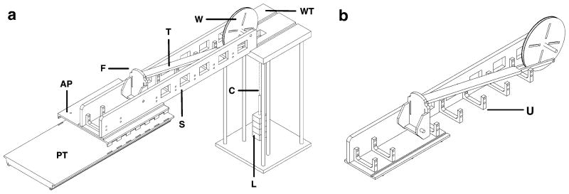
The adapter plate interfaced between the exercise assembly and the MR scanner table and was made of linen-based phenolic. It was designed with tabs projecting from its inferior surface that fit into slots on the MR scanner table used for fastening straps (Fig. 1a). Guiding holes were drilled to attach the exercise assembly to accommodate either the right or left leg. The adapter plate measured 510 × 660 mm covering the width of the scanner table and had a mass of 5 kg. The width of the adapter plate allowed one leg to rest freely while the other leg was inside the exercise assembly.
Fig. 1.
a Schematic view of exercise device components. b Schematic view of exercise assembly with one sidewall removed. PT Patient table, AP adapter plate, F footplate, T force transfer beam, S sidewall, W wheel, WT weight stand assembly, C inelastic cable, U U-shaped bracket, L lead weights
Exercise assembly
The exercise assembly consisted of a main structure, footplate, force transfer beam, and wheel. The combined mass of all exercise assembly components was 19 kg.
Main structure
The main structure consisted of a base and two side walls (Fig. 1a). The base was made of polycarbonate and had inferiorly projecting pegs to fit into the guiding holes of the adapter plate. The base and side walls fit together using a tongue and groove design and were fastened using nylon screws. The side walls were constructed of white oak, and their total mass was decreased by removing square sections. U-shaped brackets made of polycarbonate were fastened with nylon screws to the main structure and sidewalls for added stability (Fig. 1a, b). The main structure measured 1,650×240×180 mm (length × width × height) and is expected to accommodate most leg sizes.
Footplate
The footplate was designed to accommodate either foot, with a heel support and slots to pass hook and loop straps to ensure the heel and forefoot remained in contact with the footplate throughout the range of motion, regardless of plantar- or dorsiflexion. The footplate was made of polycarbonate, measured 250 × 125 mm (length × width), and was suspended by an axis of two nylon bushings about which it rotated during exercise. The axis of rotation was at the expected location of the ankle joint in order to guide foot motion during exercise and to approximate linear transfer of force. The bottom surface of the footplate had an attachment point for the force transfer beam.
Force transfer beam
The force transfer beam attached to the footplate on one end and to the wheel at the opposite end. The 1,170 mm length of the force transfer beam and location of its attachments were chosen to approximate linear transfer of force. To accomplish this, the footplate and wheel attachment sites approximated a moment arm angle of 90° with the foot in neutral position (half way between plantar- and dorsiflexion). The wheel attachment was placed 165 mm from the point of rotation, approximating the radius of foot rotation (distance from the ankle to the ball of the foot). To maintain a near-perpendicular moment arm throughout the ankle’s range of motion, the wheel and force transfer beam had the largest diameter and longest length possible, respectively, within our space constraints. The resulting beam position when attached to the wheel was 30° below the horizontal. Most subjects were expected to have plantar- and dorsiflexion ranges of motion around 35° and 20°, respectively [9]. Designing the moment arm perpendicular to the direction of force at the midpoint of rotation minimized its magnitude of deviation during exercise. The force transfer beam was built from polycarbonate, and the materials were fastened with aluminum screws. Aluminum was better suited to connect the beam to the wheel because the beam split into two thin sections (Fig. 1b).
Wheel
When the subject performed exercise causing rotation of the footplate, the beam transferred the force to the wheel, which in turn rotated and lifted a weight stack. The radius of rotation for the wheel was matched to the radius of the footplate in order to ensure the force applied translated equally to the weights. The wheel was built of a central layer of polycarbonate and two outer layers of aluminum, which were secured with aluminum screws. The wheel rotated about an aluminum axle suspended in nylon bushings to minimize friction. A woven, inelastic fabric cable from which the weights were suspended was attached to the wheel with two possible configurations: over the wheel away from the subject for plantarflexion exercise and towards the subject for dorsiflexion exercise. The cable was attached to the wheel by a twist screw and guided by flanges that extended slightly beyond the 355 mm diameter of the wheel. Radial slots were removed from the wheel to decrease its mass. While this design provided near isotonic plantar- or dorsiflexion, isometric exercise was also possible by locking the wheel in order to prevent rotation during plantar- or dorsiflexion.
Weight stand assembly
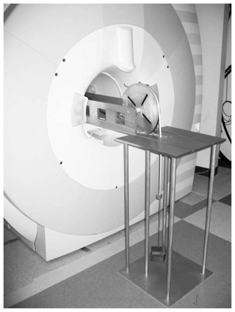
The weight stand was made of 6061-T6 aluminum alloy. Tongues in the distal portion of the exercise assembly side walls were guided into grooves on the weight stand’s top surface (Figs. 1a and 2). The exercise assembly was supported by the MR scanner table and by the weight stand, which decreased the amount of weight on the scanner table and provided capacity to support the weight of most subjects in addition to the device. Six aluminum rods connected the weight stand top and bottom plates, which measured 510×510 mm. The height of the weight stand was 1,060 mm to match the height of the patient table. All parts of the weight stand were assembled and secured with aluminum screws, and the total mass was 27 kg.
Fig. 2.
Photograph of distal portion of MR-compatible exercise device inside the magnet bore, supported by the weight stand assembly
In order to minimize friction a free-hanging weight stack was used (Figs. 1a and 2). Various weights were machined from lead and were secured onto a threaded rod and suspended from the fabric cable attached to the wheel, allowing for easy adjustment of resistance in specific increments.
Subjects and dynamic MR acquisition (31P-MRS)
Healthy male subjects participating in baseline studies for a clinical trial underwent exercise testing using the device. The study was approved by our institution’s IRB, and subjects provided informed consent prior to MR scanning. All subjects wore socks without shoes during the testing. The dynamic MR acquisition performed for validation was 31P-MRS on a 3.0 T whole body MR scanner (Trio, Siemens Medical Systems, Erlangen, Germany). The exercise device was assembled, and subjects were placed supine and feet first in the bore with their right lower leg inside the exercise device. A 13-cm-diameter custom-built single-tuned 31P surface coil was placed in contact with the posterior calf muscles. Initially, 31P spectra were acquired from the resting muscles under fully relaxed conditions [repetition time (TR) 15,000 ms, time-to-echo (TE) 0.225 ms, 16 averages, bandwidth 2,000 Hz, flip angle 90°). Next, a short series of plantarflexion movements were performed without weight resistance to familiarize the subject to the exercise device. Single-average 31P spectra were obtained every 2 s over a 10-min period, with each repetition of exercise consisting of the foot beginning in neutral position (i.e., perpendicular to the leg), performing plantarflexion against resistance, and returning to neutral position. Maximum voluntary contraction (MVC) for plantarflexion was determined before the exercise protocol based on the maximum force applied against a handheld dynamometer (microFet2, Hoggan Health Industries, West Jordan, UT). The exercise protocol consisted of 2 min of rest (60 acquisitions), followed by 3 min of plantarflexion against a load of 30% MVC (90 acquisitions) at a constant frequency of 0.5 Hz (every 2 s), followed by 5 min of recovery (150 acquisitions).
Data processing and analysis
Phosphocreatine (PCr), inorganic phosphate (Pi), and adenosine triphosphate (ATP) resonances were fitted in the time domain using the AMARES routine in jMRUI software (version 4.0) [10]. Correction for partial saturation was performed assuming T1 relaxation times at 3.0 T for PCr, Pi, and β-ATP of 6.4, 5.2, and 3.5 s, respectively [11]. Absolute concentrations were calculated assuming muscle ATP concentration of 8.2 mM [12], and intracellular pH was estimated based on the chemical shift difference between PCr and Pi resonances [13]. Mitochondrial function was determined by plotting the PCr peak integrated area vs. time during exercise recovery and fitting recovery curves to a mono-exponential function to determine the recovery time constant (τ PCr) [13, 14] using matNMR software (version 3.9.94) [15]. Statistical analyses were performed using JMP Statistical Database Software (SAS Institute, Cary, NC). Data are expressed as means ± standard deviation. ATP concentrations are expressed in mM/L cell water (mM).
Results
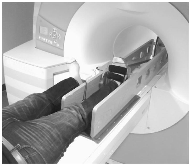
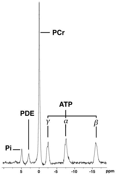
Five healthy male subjects (mean age 35 years; range 25 to 39 years) participated in the study. The exercise device components did not come within 5 mm of the scanner bore at any point. External forces applied to the exercise device were not transmitted to the housing of magnet bore. All subjects could comfortably complete the exercise protocol, with adequate room for plantarflexion while the opposite lower limb was positioned beside the exercising leg (Fig. 3). Pre-exercise (resting) 31P-MRS data obtained from subjects with the leg and device in the magnet bore showed excellent quality (Fig. 4).
Fig. 3.
Photograph of the MR-compatible exercise device and subject before entering the magnet bore
Fig. 4.
Pre-exercise 31P-MR spectrum (TR 15,000 ms, TE 0.225 ms, 16 averages, bandwidth 2,000 Hz, flip angle 90°) from the posterior calf muscles of a 34-year-old male subject obtained during rest with leg and exercise device inside magnet bore, showing excellent spectral quality. Pi Inorganic phosphate, PDE phosphodiesters, PCr phosphocreatine, ATP adenosine triphosphate
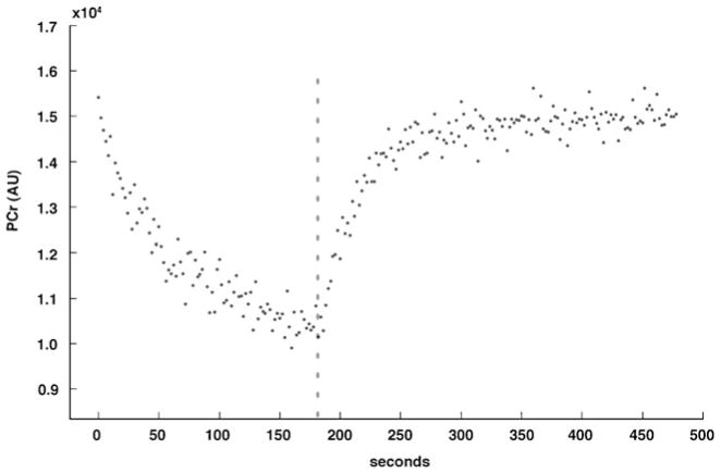
The exercise protocol caused expected changes in PCr (Fig. 5) and Pi concentrations, while ATP concentrations remained constant. The average PCr, β-ATP, and pH in the posterior calf muscles during the final 10 s of rest and during the final 10 s of plantarflexion exercise are outlined in Table 1. The PCr content was significantly decreased (P=0.005), with negligible changes to β-ATP concentrations. The significant depletion of PCr at end of exercise suggested adequate participant effort, with PCr to Pi ratios of less than 4 (mean 1.65±0.6) [13]. The mean τPCr was 35.3±8.3 s.
Fig. 5.
PCr concentration changes during and following plantar-flexion submaximal exercise. Dashed line represents end of exercise (t=180 s)
Table 1.
Changes observed in five subjects after exercise protocol
| Parameter | End rest (t=120 s) | End exercise (t=300 s) | Percent change |
|---|---|---|---|
| PCr concentration (mM) | 30.4±3.0 | 21.8±3.9 | −28% |
| Pi concentration (mM) | 6.5±3.3 | 14.6±4.7 | +123% |
| β-ATP concentration (mM) | 8.2a | 8.06±0.5 | −2% |
| Muscle pH | 7.17±0.07 | 7.06±0.14 | −1.5% |
Data are expressed as mean± standard deviation
Resting ATP concentration was set at 8.2 mM [12]
Discussion
An important goal of this exercise device was to create a means for providing a standardized workload to lower leg muscles that could be implemented in clinical scanners. In contrast to thigh muscles that have mixed fiber types, calf muscles such as the soleus and tibialis anterior contain dominant fractions of slow- (type I) and fast-twitch (type II) fibers, respectively [16]. In addition, their anatomical location is advantageous for optimal magnetic field centering, making these muscles the preferred target for spectroscopic investigations. With the expanding literature on 1H-MRS of calf muscles for determination of lipid concentrations in insulin resistance, there is a strong case for assessment of high energy phosphates of these same muscles via 31P-MRS [17]. Furthermore, our exercise device can be employed in other clinical applications, such as dynamic investigations of the ankle in cases of tendon subluxations/dislocations (e.g., peroneal tendons), or when it would be of interest to examine the calf muscle signal during/after exercise, such as in suspected compartment syndromes.
Our results show the successful development and implementation of a modular exercise device for lower leg muscles that can be used with a clinical 3 T whole-body MR scanner. We also demonstrate that the device allowed acquisition of high-quality dynamic 31P spectra for determination of PCr recovery rates in human subjects during isotonic submaximal workloads. Because of its modular characteristics, the device was quickly set up in a busy clinical environment and could potentially fit other clinical whole-body scanners. Another important feature of our device design was its capability to exercise either leg, and to evaluate plantarflexion or dorsiflexion muscles.
The metabolite concentration data acquired using our exercise device were comparable to prior investigations using submaximal exercise protocols. Following low-intensity (0.33 Hz) calf muscle exercise in humans, Forbes et al. [14] observed that PCr recovery was well characterized by a mono-exponential model with recovery rates of 35±4 s. In addition, our data are consistent with decreases in PCr between 16 and 40% observed during submaximal workload to the thigh muscles [12]. While our results are from submaximal calf muscle exercise, our device can be configured to impose maximal or near-maximal exercise workloads.
The proposed design has certain limitations. All parts of the exercise device located inside the magnet bore were made of nonmetallic materials. Metallic nonferrous materials (i.e., aluminum layers of wheel) were located outside the bore. It is possible that eddy currents could affect the aluminum wheel during exercise and cause obstructive torque that would further add workload to the prescribed weight resistance. At 1.5 T, Jeneson et al. [12] concluded that eddy effects on the resistance of an exercise device with nonferrous metallic parts inside the magnet caused a small but acceptable increase in workload. Another limitation in our implementation was the lack of power output quantification through measurement of force and angular displacement using electronic transducers. This could lead to under- or overestimation of power output and exercise intensity, which could affect muscle metabolites measured with 31P-MRS. This issue could be resolved by incorporating transducers and computer-controlled data acquisition systems to measure force output and ankle range of motion during exercise [7]. While our exercise device is not currently available for commercial distribution, the description of its overall structure may serve as a framework for others to build similar in-house devices.
In summary, the proposed modular exercise device was successfully implemented in a busy clinical environment and clinical MR scanner allowing acquisition of dynamic data from calf musculature during exercise and post-exercise recovery. The device can be easily adapted to most clinical MR scanners and represents a valuable tool for investigation of muscle physiology, with potential use in protocols requiring MRI or MRS data acquisition during and immediately after exercise of calf muscles.
Acknowledgments
This work was supported in part by National Institutes of Health Grants RO1 HL-077674, UL1 RR025758, and K23 RR-23090.
Contributor Information
Reza Hosseini Ghomi, Musculoskeletal Imaging and Intervention, Department of Radiology, Massachusetts General Hospital and Harvard Medical School, 55 Fruit Street, YAW 6048, Boston, MA 02114, USA.
Miriam A. Bredella, Musculoskeletal Imaging and Intervention, Department of Radiology, Massachusetts General Hospital and Harvard Medical School, 55 Fruit Street, YAW 6048, Boston, MA 02114, USA
Bijoy J. Thomas, Musculoskeletal Imaging and Intervention, Department of Radiology, Massachusetts General Hospital and Harvard Medical School, 55 Fruit Street, YAW 6048, Boston, MA 02114, USA
Karen K. Miller, Neuroendocrine Unit, Massachusetts General Hospital and Harvard Medical School, Boston, MA, USA
Martin Torriani, Email: mtorriani@hms.harvard.edu, Musculoskeletal Imaging and Intervention, Department of Radiology, Massachusetts General Hospital and Harvard Medical School, 55 Fruit Street, YAW 6048, Boston, MA 02114, USA.
References
- 1.Argov Z, Lofberg M, Arnold DL. Insights into muscle diseases gained by phosphorus magnetic resonance spectroscopy. Muscle Nerve. 2000;23:1316–34. doi: 10.1002/1097-4598(200009)23:9<1316::aid-mus2>3.0.co;2-i. [DOI] [PubMed] [Google Scholar]
- 2.Quistorff B, Nielsen S, Thomsen C, Jensen KE, Henriksen O. A simple calf muscle ergometer for use in a standard whole-body MR scanner. Magn Reson Med. 1990;13:444–9. doi: 10.1002/mrm.1910130311. [DOI] [PubMed] [Google Scholar]
- 3.Isbell DC, Epstein FH, Zhong X, DiMaria JM, Berr SS, Meyer CH, et al. Calf muscle perfusion at peak exercise in peripheral arterial disease: measurement by first-pass contrast-enhanced magnetic resonance imaging. J Magn Reson Imaging. 2007;25:1013–20. doi: 10.1002/jmri.20899. [DOI] [PMC free article] [PubMed] [Google Scholar]
- 4.Meyerspeer M, Krssak M, Kemp GJ, Roden M, Moser E. Dynamic interleaved 1H/31P STEAM MRS at 3 Tesla using a pneumatic force-controlled plantar flexion exercise rig. MAGMA. 2005;18:257–62. doi: 10.1007/s10334-005-0014-y. [DOI] [PMC free article] [PubMed] [Google Scholar]
- 5.Ryschon TW, Fowler MD, Arai AA, Wysong RE, Leighton SB, Clem TR, Sr, et al. A multimode dynamometer for in vivo MRS studies of human skeletal muscle. J Appl Physiol. 1995;79:2139–47. doi: 10.1152/jappl.1995.79.6.2139. [DOI] [PubMed] [Google Scholar]
- 6.Francescato MP, Cettolo V. Two-pedal ergometer for in vivo MRS studies of human calf muscles. Magn Reson Med. 2001;46:1000–5. doi: 10.1002/mrm.1287. [DOI] [PubMed] [Google Scholar]
- 7.Raymer GH, Allman BL, Rice CL, Marsh GD, Thompson RT. Characteristics of a MR-compatible ankle exercise ergometer for a 3.0 T head-only MR scanner. Med Eng Phys. 2006;28:489–94. doi: 10.1016/j.medengphy.2005.07.021. [DOI] [PubMed] [Google Scholar]
- 8.Graf H, Lauer UA, Schick F. Eddy-current induction in extended metallic parts as a source of considerable torsional moment. J Magn Reson Imaging. 2006;23:585–90. doi: 10.1002/jmri.20539. [DOI] [PubMed] [Google Scholar]
- 9.Allinger TL, Engsberg JR. A method to determine the range of motion of the ankle joint complex, in vivo. J Biomech. 1993;26:69–76. doi: 10.1016/0021-9290(93)90614-k. [DOI] [PubMed] [Google Scholar]
- 10.Vanhamme L, van den Boogaart A, Van Huffel S. Improved method for accurate and efficient quantification of MRS data with use of prior knowledge. J Magn Reson. 1997;129:35–43. doi: 10.1006/jmre.1997.1244. [DOI] [PubMed] [Google Scholar]
- 11.Meyerspeer M, Krssak M, Moser E. Relaxation times of 31P-metabolites in human calf muscle at 3 T. Magn Reson Med. 2003;49:620–5. doi: 10.1002/mrm.10426. [DOI] [PubMed] [Google Scholar]
- 12.Jeneson JA, Schmitz JP, Hilbers PA, Nicolay K. An MR-compatible bicycle ergometer for in-magnet whole-body human exercise testing. Magn Reson Med. 2010;63:257–61. doi: 10.1002/mrm.22179. [DOI] [PubMed] [Google Scholar]
- 13.Fleischman A, Kron M, Systrom DM, Hrovat M, Grinspoon SK. Mitochondrial function and insulin resistance in overweight and normal-weight children. J Clin Endocrinol Metab. 2009;94:4923–30. doi: 10.1210/jc.2009-1590. [DOI] [PMC free article] [PubMed] [Google Scholar]
- 14.Forbes SC, Paganini AT, Slade JM, Towse TF, Meyer RA. Phosphocreatine recovery kinetics following low- and high-intensity exercise in human triceps surae and rat posterior hindlimb muscles. Am J Physiol Regul Integr Comp Physiol. 2009;296:R161–170. doi: 10.1152/ajpregu.90704.2008. [DOI] [PMC free article] [PubMed] [Google Scholar]
- 15.van Beek JD. matNMR: a flexible toolbox for processing, analyzing and visualizing magnetic resonance data in Matlab. J Magn Reson. 2007;187:19–26. doi: 10.1016/j.jmr.2007.03.017. [DOI] [PubMed] [Google Scholar]
- 16.Johnson MA, Polgar J, Weightman D, Appleton D. Data on the distribution of fibre types in thirty-six human muscles. An autopsy study. J Neurol Sci. 1973;18:111–29. doi: 10.1016/0022-510x(73)90023-3. [DOI] [PubMed] [Google Scholar]
- 17.Schrauwen-Hinderling VB, Kooi ME, Hesselink MK, Jeneson JA, Backes WH, van Echteld CJ, et al. Impaired in vivo mitochondrial function but similar intramyocellular lipid content in patients with type 2 diabetes mellitus and BMI-matched control subjects. Diabetologia. 2007;50:113–20. doi: 10.1007/s00125-006-0475-1. [DOI] [PubMed] [Google Scholar]


