Abstract
A positron emission mammograph (PEM) is an organ dedicated positron emission tomography (PET) scanner for breast cancer detection. State-of-the-art PEMs employing scintillating crystals as detection medium can provide metabolic images of the breast with significantly higher sensitivity and specificity with respect to standard whole body PET scanners. Over the past few years, crystal PEMs have dramatically increased their importance in the diagnosis and treatment of early stage breast cancer. Nevertheless, designs based on scintillators are characterized by an intrinsic deficiency of the depth of interaction (DOI) information from relatively thick crystals constraining the size of the smallest detectable tumor.
This work shows how to overcome such intrinsic limitation by substituting scintillating crystals with pixelated CdTe detectors. The proposed novel design is developed within the Voxel Imaging PET (VIP) Pathfinder project and evaluated via Monte Carlo simulation. The volumetric spatial resolution of the VIP-PEM is expected to be up to 6 times better than standard commercial devices with a point spread function of 1 mm full width at half maximum (FWHM) in all directions. Pixelated CdTe detectors can also provide an energy resolution as low as 1.5% FWHM at 511 keV for a virtually pure signal with negligible contribution from scattered events.
Keywords: Gamma camera, SPECT, PET PET/CT, coronary CT angiography (CTA), Solid state detectors, Pixelated detectors and associated VLSI electronics, X-ray mammography and scinto- and MRI-mammography
1 Introduction
A positron emission mammograph (PEM) is an organ dedicated Positron Emission Tomography (PET) scanner for breast screening [1, 2]. PEMs have a restricted field of view (FOV) to achieve higher cancer detection performance in terms of both sensitivity and specificity with respect to the conventional whole-body PET scanners [3]. Extra benefits include lower needed dose, lower cost, and enhanced device portability. The increasing interest in PEMs is also due to their recent employment in PET driven breast biopsies to exploit the advantage of functional over anatomic imaging in discriminating a benign process such as a scar from malignancy [4].
Several designs have been proposed and developed [5-7] with different geometrical solutions to limit the FOV around the imaged breast and axilla. The most commonly available commercial devices employ arrays of scintillating crystal detectors mounted on two parallel paddles whose distance can be regulated for breast immobilization [6] in a mammography-like fashion, thus offering an ideal instrument for PET driven breast biopsies and PET-CT image co-registration [8]. Such devices can provide excellent in-plane1 spatial resolution down to 2 mm full width at half maximum (FWHM) [9] and high contrast images with 4 mm and 6 mm minimum detectable lesion size for 10:1 and 4:1 tumor to normal tissue ratio (TNR) respectively [6]. A number of clinical trials have been conducted over the past few years to show the huge potential of PEM devices in improving breast cancer treatment [10-12]. In particular, PEM showed higher sensitivity with respect to conventional PET/CT in diagnosis and characterization of small breast tumors (< 2 cm diameter), though such sensitivity is significantly reduced for very small lesions (< 1 cm diameter) [11]. Improving the tumor detectability limit for mm size lesions would dramatically increase the medical impact of PEMs and provide high specificity metabolic images in a region where only anatomic images are currently available.
Designs based on scintillators present a number of limiting factors including a relatively poor energy resolution (5-10% for commonly used crystals [13]), the incompatibility with strong magnetic fields when coupled with photo-multipliers (PMT), and relatively large parallax error due to the deficiency of the depth of interaction (DOI) information (> 5 mm FWHM) from scintillating crystals [14]. All these effects contribute to the deterioration of the detector sensitivity and image quality. In particular, the large DOI uncertainty has the biggest impact on the capability of detecting small size tumors, regardless of the chosen geometry [16]. This is due to the partial volume effect [15] that produces a loss of intensity and the smearing of the activity distribution around those high uptake regions whose volume is smaller than twice the detector resolution. In the particular case of coplanar scanners, a large parallax error results in dramatic deterioration of the resolution up to 8 mm FWHM along the vertical axis [6], a factor of 4 worse than the spatial resolution in the in-plane. This poses a serious constraint on the minimum detectable tumor size and on the correct assessment of the malignancy of small lesions which are probably the two most important factors to determine the effectiveness of any breast cancer treatment [17]. Drawbacks to the limited cross-plane2 resolution are also evident when using PEMs for PET driven breast biopsies for which the correct vertical position must be guessed on statistical extrapolation and repeated sampling (up to 12 trials) and post-biopsy confirmation scans are necessary to correctly locate the lesion [4].
In the framework of the Voxel Imaging PET (VIP) Pathfinder project [18, 19], we propose a novel PEM design based on finely segmented room temperature CdTe detectors to overcome the intrinsic limitations of state-of-the-art commercial PEMs based on scintillating crystals. In this study, the proposed design is simulated and evaluated in terms of sensitivity, spatial resolution, and the minimum detectable tumor size.
2 Detector specifications and simulation setup
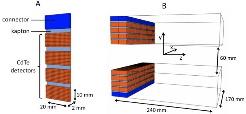
The VIP-PEM is based on the VIP unit detector module (figure 1 A) made of four CdTe pixelated detectors bonded to a thinned read out chip (ROC) and then mounted on a kapton printed circuit board (PCB). Each one of the four detectors has a parallelepiped shape with 2 cm × 1 cm surface and 2 mm thickness. The 2000 V high voltage is applied such to have the electric field perpendicular to the surface with resulting 1000 V/mm bias and an expected energy resolution of 1.5% for 511 keV photons at room temperature [20]. The CdTe detectors are segmented into 1 mm × 1 mm pixels for a total of 4 × 200 channels per module. The ROC and the PCB are 50 μm thick each, and a 15 μm additional thickness is due to the conductive glue between the ROC, the PCB, and the CdTe detectors. The combined attenuation coefficient of the passive material accounts for less than 2% compared to 2 mm CdTe. To obtain the energy and time information, each channel is bonded to a microchip hosting a fully integrated front-end electronic. Finally, one side of the module hosts an electronic connector to the external bus.
Figure 1.
Basic unit detector (A) and full detector (B) geometrical specifications.
The VIP modular design is extremely versatile with the possibility to build virtually any detector geometry by stacking the needed number of modules in arbitrary patterns. The resulting detector has a 3-D segmentation with a channel density of ~ 470 voxels per cm3. The positioning of the module with respect to the incident radiation, with photons entering from the opposite side with respect to the electronic connector, is a key feature introduced to maximize the stopping power and minimize the amount of passive material of the final scanner. In the proposed design, incident radiation is facing a minimum of 4 cm depth of interaction in CdTe.
Following the typical coplanar design, the VIP mammograph consists of two parallel paddles, each one hosting one sliding detector head. The two heads are made of 80 modules each, arranged along two parallel lines of 40 modules for a total of 64000 channels per head.
The coordinate system is chosen as in figure 1 B and centered in the center of the FOV. For the tests described in this paper, the distance between the two paddles along the y-axis is fixed at 60 mm, but can in principle be varied arbitrarily. The head section is 170 mm wide along the x-axis and 40 mm wide along the z-axis, and the two detector heads must slide axially for a complete scan of the 170 mm × 60 mm × 240 mm FOV.
3 Analysis method
The full device is simulated using the Geant4-based Architecture for Medicine-Oriented Simulations (GAMOS) [21]. Due to the large number of channels in the detector (> 105), each channel is treated as an independent detector with data collected in list mode and processed offline. Entries of the data list are regarded as hits and characterized by the (x,y,z) position of the center of the correspondent voxel, the collected energy, and the time stamp. A channel activates if the energy deposited exceeds the 20 keV trigger threshold. The trigger defines the time stamp of the hit followed by 10 μs measuring time and 25 μs dead time. All energy depositions within the same voxel and within the measuring time contribute to the total energy of a single hit while energies deposited within the dead time are lost. The coincidence searching algorithm processes the list mode data to group consecutive hits laying inside a coincidence time window of 20 ns. Within a group of coincident hits, energies of hits whose reciprocal distance is below 2 mm are added together and the new position assigned to the E-weighted centroid. After merging, only coincidences with two hits are considered with both the corresponding collected energies equal to 511 keV with ±1.5% tolerance. Images are reconstructed with a standard filtered back-projection (FBP) algorithm with no correction applied.
The scans of three different phantoms have been simulated to evaluate the counting and imaging performance of the proposed device. At first, a single point-like source as defined in the NU 4-2008 standards of the National Electrical Manufacturers Association (NEMA) [22] is placed in different positions to estimate the expected sensitivity and the point spread function (PSF) across the FOV. Secondly, the expected scatter and random coincidence fractions are measured following the prescription of the NEMA NU 4-2008 and employing a high density rat-like phantom. Finally, the test for assessing the minimum tumor size is performed using an ad-hoc cylindrical phantom with 20 mm radius and 30 mm length placed in the center of the FOV along the z-axis. The phantom is filled with a fluorodeoxyglucose (FDG) solution with activity A=5 Bq/mm3. A sphere of variable radius, from 0.5 mm to 2 mm in 0.5 mm steps, is placed off-center inside the cylinder and filled with an FDG solution with activity A=15 Bq/mm3 for a 3:1 TNR.
4 Results
4.1 Sensitivity and spatial resolution
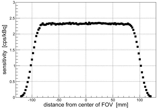
The sensitivity is defined as the number of collected coincidences divided by the total number of events. Values of the sensitivity for a point-like source placed in different positions along the z-axis are presented in figure 2. As expected for a detector with sliding heads, the sensitivity is flat across most of the FOV and goes quickly to zero at the edges. The estimated average sensitivity is around 2 cps/kBq. The results are compatible with those obtained when evaluating crystal PEMs with analogous coplanar geometry and sliding heads [9].
Figure 2.
Values of sensitivity for a 22Na point-like source in different positions along the z-axis (axial scan).
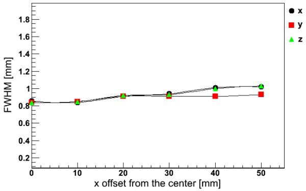
Images of the point-like source are reconstructed to obtain the corresponding PSF. Figure 3 shows the values of the PSF for different positions of the source along the x-axis. Simulation results indicate a spatial resolution around 1 mm FWHM regardless of the direction.
Figure 3.
Values of the PSF measured along the x, y, and z directions for a 22Na point-like source in different positions along the x-axis (transverse scan).
4.2 Scatter and random fractions
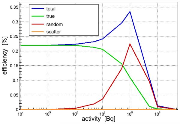
The number of true, scatter, and random events are directly available from simulation and shown in figure 4 for different values of the total integrated activity in the FOV. Due to the excellent energy resolution of the CdTe, the contamination from scatter events is negligible at any value of the activity. The random fraction is negligible up to 106 Bq and peaks at around 108 Bq. Saturation effects become evident for activity bigger than 108 Bq, well above the level expected in a standard positron emission mammography (~ 106 Bq).
Figure 4.
Values of coincidence rate as a function of activity concentration in the rat-like phantom as defined in the NEMA NU 4-2008 report [22]. Rate values for true, random, and scatter events are shown separately for comparison.
4.3 Tumor size
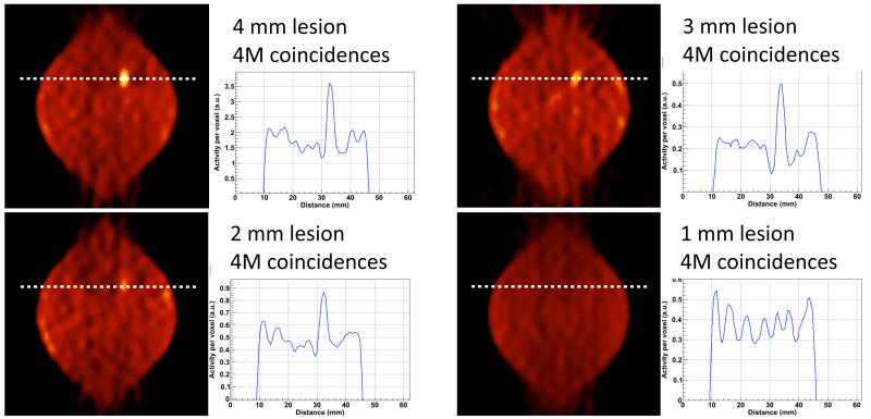
Four different hot lesions with diameter from 1 mm to 4 mm in a uniform warm background are simulated with 3:1 TNR. A total of 4M coincidences are collected for each lesion corresponding to a 15 minutes scan for typical whole body injection of 300 MBq and assuming an average standard uptake value (SUV) of 0.81 for a normal breast tissue [23]. The images are reconstructed with FBP and no corrections are applied to minimize the impact of the imaging technique on the image quality. Results in figure 5 show that lesions down to 2 mm diameter are clearly visible, though the deterioration of the image contrast due to the partial volume effect is already evident for the 3 mm diameter lesion. The leaf-like shape instead of the simulated circular source distribution is an artifact of FBP due to the limited angular coverage.
Figure 5.
FBP reconstructed images and correspondent line of response of hot lesions over warm background. The simulated TNR is 3:1 for all the images. Four different lesion sizes are displayed: 4 mm diameter (top-left), 3 mm diameter (top-right), 2 mm diameter (bottom-left), and 1 mm diameter (bottom-right). The four images correspond to the same transaxial section of the FOV, aligned with the lesion known position and with 0.5 mm thickness. The activity along the indicated line of response is shown for each image. All images are reconstructed with 4M prompt events.
5 Conclusion
The present paper reports on the evaluation of a novel conceptual PEM design with the aim of proving the feasibility of using pixelated CdTe diode detectors to overcome the limitations of state-of-the-art PEMs based on scintillating crystals. Results from simulation cover the assessment of the expected counting and imaging performance of the proposed device. With a sensitivity of 2 cps/kBq and a PSF of 1 mm FWHM along the three spatial directions, the VIP-PEM has 6 times better volumetric resolution with respect to conventional scanners and can detect lesions down to 2 mm diameter with a 3:1 TNR. The results show the potential of the novel design for providing high specificity metabolic images for very small lesions and low TNR. A fully operative dual head prototype is being developed within the framework of the VIP project to confirm the simulation findings.
Acknowledgments
This work has been supported by the FP7-ERC advanced grant #250207.
Footnotes
Parallel to the paddle surfaces.
Perpendicular to the paddle surfaces.
References
- [1].Thompson CJ, Murthy K, Weinberg IN, Mako F. Feasibility Study for Positron Emission Mammography. Med. Phys. 1994;21:529. doi: 10.1118/1.597169. [DOI] [PubMed] [Google Scholar]
- [2].Thompson CJ, Murthy K, Weinberg IN, Mako F. Positron Emission Mammography (PEM): A Promising Technique for Detecting Breast Cancer. IEEE Trans. Nucl. Sci. 1995;NS42:1012. [Google Scholar]
- [3].Shilling K. The role of positron emission mammography in breast cancer imaging and management. Appl. Radiol. 2008;37:26. [Google Scholar]
- [4].Kalinyak JE, et al. PET-Guided Breast Biopsy. The Breast Journal. 2011;17:143. doi: 10.1111/j.1524-4741.2010.01044.x. [DOI] [PubMed] [Google Scholar]
- [5].Furuta M, et al. Basic evaluation of a C-shaped breast PET scanner. IEEE Nucl. Sci. Symp. Conf. Rec. 2009:2548. [Google Scholar]
- [6].MacDonald L, et al. Clinical imaging characteristics of the positron emission mammography camera: PEM Flex Solo II. J Nucl. Med. 2009;50:1666. doi: 10.2967/jnumed.109.064345. [DOI] [PMC free article] [PubMed] [Google Scholar]
- [7].Abreu MC, et al. Design and Evaluation of the ClearPEM Scanner for Positron Emission Mammography. IEEE Trans. Nucl. Sci. 2006;53:71. [Google Scholar]
- [8].Murthy K, et al. Results of Preliminary Clinical Trials of the Positron Emission Mammography System PEM-I: A Dedicated Breast Imaging System Producing Glucose Metabolic Images Using FDG. J. Nucl. Med. 2000;41:1851. [PubMed] [Google Scholar]
- [9].Luo W, et al. Performance Evaluation of a PEM Scanner Using the NEMA NU 4-2008 Small Animal PET Standards. IEEE Trans. Nucl. Sci. 2010;57:94. [Google Scholar]
- [10].Iima M, et al. Clinical Performance of 2 Dedicated PET Scanners for Breast Imaging: Initial Evaluation. J. Nucl. Med. 2012;53:1. doi: 10.2967/jnumed.111.100958. [DOI] [PubMed] [Google Scholar]
- [11].Eo JS, et al. Imaging sensitivity of dedicated positron emission mammography in relation to tumor size. Breast. 2012;21:66. doi: 10.1016/j.breast.2011.08.002. [DOI] [PubMed] [Google Scholar]
- [12].http://clinicaltrials.gov/ct2/show/study/NCT01569321.
- [13].Knoll GF. Radiation Detection and Measurements. John Wiley and Sons, Inc.; New York U.S.A.: 2010. [Google Scholar]
- [14].Lerche CW, et al. Dependency of Energy-, Position- and Depth of Interaction Resolution on Scintillation Crystal Coating and Geometry. IEEE Trans. Nucl. Sci. 2008;55:1344. [Google Scholar]
- [15].Saha GB. Basics of PET Imaging. Springer Science+Business Media, Inc.; New York U.S.A.: 2005. [Google Scholar]
- [16].Moses WW, Qi J. Instrumentation optimization for positron emission mammography. Nucl. Instrum. Meth. A. 2004;527:76. [Google Scholar]
- [17].Breast Cancer Facts and figures 2011-2012. American Cancer Society; 2012. [Google Scholar]
- [18].Chmeissani M, et al. Modeling and simulation of PET scanner based on pixelated solid-state detector. IEEE Nucl. Sci. Symp. Conf. Rec. 2009:3496. [Google Scholar]
- [19].Mikhaylova E, et al. Simulation of pseudo-clinical conditions and image quality evaluation of PET scanner based on pixelated CdTe detector. IEEE Nucl. Sci. Symp. Conf. Rec. 2011:2716. [Google Scholar]
- [20].Ariño G, et al. Energy and Coincidence Time Resolution Measurements of CdTe Detectors for PET. Int. Workshop Radiat. Imag. Detect. Conf. Rec. 2012 doi: 10.1088/1748-0221/8/02/C02015. [DOI] [PMC free article] [PubMed] [Google Scholar]
- [21].Arce P, et al. GAMOS: An easy and flexible way to use GEANT4. IEEE Nucl. Sci. Symp. Conf. Rec. 2011:2230. [Google Scholar]
- [22].NEMA Standards Publication NU 4-2008 . Performance Measurements of Small Animal Positron Emission Tomographs. National Electrical Manufacturers Association; Rosslyn, VA: 2008. [Google Scholar]
- [23].Kumar R, et al. Standardized Uptake Values of Normal Breast Tissue with 2-Deoxy-2-[F-18]Fluoro-D -glucose Positron Emission Tomography: Variations with Age, Breast Density, and Menopausal Status. Mol. Imaging Biol. 2006;8:355. doi: 10.1007/s11307-006-0060-5. [DOI] [PubMed] [Google Scholar]


