Abstract
This report details the first experimental results from novel hydrogel sensor array (2 × 2) which incorporates analyte diffusion pores into a piezoresistive diaphragm for the detection of hydrogel swelling pressures and hence chemical concentrations. The sensor assembly was comprised of three components, the active four sensors, HPMA/DMA/TEGDMA (hydroxypropyl methacrylate (HPMA), N,N-dimethylaminoethyl methacrylate (DMA) and crosslinker tetra-ethyleneglycol dimethacrylate (TEGDMA)) hydrogel, and backing plate.
Each of the individual sensors of the array can be used with various hydrogels used to measure the presence of a number of stimuli including pH, ionic strength, and glucose concentrations. Ideally, in the future, these sensors will be used for continuous metabolic monitoring applications and implanted subcutaneously. In this paper and to properly characterize the sensor assembly, hydrogels sensitive to changes ionic strength were synthesized using hydroxypropyl methacrylate (HPMA), N,N-dimethylaminoethyl methacrylate (DMA) and crosslinker tetra-ethyleneglycol dimethacrylate (TEGDMA) and inserted into the sensor assembly. This hydrogel quickly and reversibly swells when placed environments of physiological buffer solutions (PBS) with ionic strengths ranging from 0.025 to 0.15 M, making it ideal for proof-of-concept testing and initial characterization.
The assembly was wire bonded to a printed circuit board and coated with 3 ± 0.5 μm of Parylene-C using chemical vapor deposition (CVD) to protect the sensor and electrical connections during ionic strength wet testing. Two versions of sensors were fabricated for comparison, the first incorporated diffusion pores into the diaphragm, and the second used a solid diaphragm with perforated backing plate.
This new design (perforated diaphragm) was shown to have slightly higher sensitivity than solid diaphragm sensors with separate diffuse backing plates when coupled with the hydrogel. The sensitivities for the 1 mm × 1 mm, 1.25 mm × 1.25 mm, 1.5 mm × 1.5 mm perforated diaphragm sensors were 53.3 ± 6.5, 171.7 ± 8.8, and 271.47 ± 27.53 mV/V-M, respectively. These results show that perforations in the diaphragm can be used not only to allow the diffusion of analyte into the cavity but to increase mechanical stress in the piezoresistive diaphragm, thereby increasing sensor output signal.
The time constants for swelling (τswelling) and contracting (τcontracting) were calculated by fitting the sensor output half cycles to an exponential growth function. We found that the sensors' response was initially retarded during the preliminary hydrogel conditioning period then improved after 3–5 cycles with values of approximately 9 and 7 min for τswelling and τcontracting. For all sensors tested τswelling > τcontracting. This may be due to the increased loading on the hydrogel from the diaphragm during the swelling process. During contraction the diaphragm aids the hydrogel by reversibly applying mechanical pressure and therefore reducing τcontracting. Long term stability testing showed the sensors remained functional for upwards of 2 weeks in the test phosphate buffer solution (PBS).
Keywords: Chemical sensor, Pressure sensor, Piezoresistive, Hydrogel, Array
1. Introduction
Hydrogels are polymeric materials that consist of a crosslinked polymer network that absorbs/desorbs water in response to changes in surrounding environmental conditions. This diffusion of water within hydrogels causes swelling to occur in response to a shift in chemical potential and hence osmotic pressure. One classification of hydrogels known as “smart” or “stimuli-responsive” reversibly swell in response to changes in environmental concentrations of specific target molecules. Using these “smart” hydrogels sensor selectivity can be enhanced by attaching moieties to the hydrogel that selectively bind the analyte of interest including pH, glucose, and CO2 [1–4]. This has the advantage of making these sensors highly selective in response to a specific analyte while providing continuous monitoring. Many hydrogels are also biocompatible and highly suitable for use in implantable biomedical sensors and autonomous drug delivery devices. The response time of hydrogels was shown to improve through miniaturization by increasing the ratio of surface area to volume which increases the effective diffusion rate. Many approaches have been used to measure modifications in hydrogels optical, electrical, and mechanical properties including: holographic Bragg diffraction (optical) [5], electrode impedance (electrical) [6,7], quartz crystal microbalances (resonance) [8], and piezoresistive based cantilevers or membranes (mechanical–electrical) [4,9–12]. Another transduction mechanisms used to detect hydrogel swelling is obtained by confining a thin piece (<500 μm) of smart hydrogel between porous membrane and the diaphragm of a miniature piezoresistive pressure transducer. In this design the change in the environmental analyte concentration causes chemical diffusion through the pores of the membrane changing the osmotic swelling pressure within the hydrogel. This change in chemical potential (osmotic pressure) causes swelling and an increase of mechanical pressure within the hydrogel cavity as measured by the pressure transducer.
Fig. 1 shows two versions of “chemo-mechanical sensors” that we have fabricated that embody this sensing mechanism. The two designs differ from one another by the location of the analyte diffusion pores. The first design (Fig. 1a) uses a periodic array of diffusion channels located on the backing plate while the new design (Fig. 1b) incorporates the diffusion pores directly into the piezoresistive membrane. Previous reports have shown that sensors based on Fig. 1a have been successfully been developed to detect variations of pH [10,12–14] and CO2 [15–19]. The novel perforated diaphragm pressure sensor (Fig. 1b) we believe has a number of advantages when comparing the designs. It was previously reported that the shape, size and location of these diffusion channels can be used to manipulate the stress distribution within the diaphragm allowing the sensor to be tuned to a particular hydrogel [20]. We also envision that the pores within the diaphragm can be fabricated using a combination of potassium hydroxide (KOH) and deep reactive ion etching (DRIE) on a scale which make them behave as a semipermeable membrane. An additional advantage of this design is with the integration of the pores with the diaphragm the fabrication of a backing plate is not required.
Fig. 1.

CAD rendering of the hydrogel based pressure sensor designs utilizing analyte diffusion channels that are located (a) within the backside mounting plate and (b) within the diaphragm.
The hydrogels used in this study are composed of HPMA/DMA/TEGDMA and reversibly respond to pH and changes in ionic strength because they contain tertiary amines (on DMA) that becomes protonated. At low pH value this elevated protonation temporarily increases the osmotic swelling pressure within the hydrogel. At a fixed pH, a larger osmotic swelling pressure is also obtained by increasing the chemical potential of the surrounding water by reducing the environmental ionic strength. In either situation, the increase in osmotic pressure is compensated for by swelling of the gel and hence increased pressure found with the isochoric sensor cavity. From previous work on hydrogels of the same composition tests were performed to quantify the swelling pressure and overall response characteristics of the gels [21]. In this experiment the gels were confined between a calibrated micro-pressure sensor and a variety of wire meshes inside of a ∼3 mm stainless steel cylinder. The end of the stainless steel cylinder that contained the wire mesh and hydrogel are placed in solutions of varying ionic concentration. The pressure created within the cylinder was measured and recorded with respect to time. In all cases the measured results were taken from hydrogels with a thickness of approximately 400 μm. The physiological buffer solution (PBS) was subjected to cyclic changes in ionic strength between 0.05 and 0.15 M at fixed pH of 7.4. The response characteristics of the hydrogel were well characterized in this study for a number of alternate steel meshes and nanoporous paper membranes. It was also observed that the pressure response increases with the amount of initial hydrogel loading or how tightly the hydrogel was confined against the pressure sensor. Hydrogel swelling pressure ranged from 21 to 112 kPa with response times (τ50) from 2.9 to 9.5 min. This experiment showed that both the initial loading pressure and diffusion channel characteristics play a primary role in the overall sensor behavior. Although hydrogels used to measure changes in ionic strength may not be as physiologically significant as those that measure glucose or CO2 they have high swelling pressures, are easily synthesized, and well characterized making them ideal for preliminary sensor array characterization.
In this paper we present the fabrication and passivation of the hydrogel sensor arrays and discuss initial test results from sensors coupled with HPMA/DMA/TEGDMA hydrogels. Ideally, each of the four cavities was optimized for a particular pressure range which was defined by the measured swelling pressures of hydrogels used for the detection of ionic strength, pH, and glucose concentration with reference. Future research will be focused directly on coupling the devices to glucose sensitive hydrogels. In this report the output characteristics for both solid and perforated diaphragms (Fig. 1b) sensors are reported in response to changes of ionic strength for various PBS mixtures using only the HPMA/DMA/TEGDMA hydrogels.
2. Sensor assembly
2.1. Sensor dies
Sensor assemblies were comprised of three main components. First, a square silicon micro-pressure sensor arrays were used for the detection hydrogel swelling pressures. These sensor dies were designed with both solid and perforated square silicon diaphragms with widths of 1.0, 1.25, and 1.5 mm used to measure pressures of 150, 50, 25, 5 kPa, respectively, shown in Fig. 2. A 14 step fabrication process was performed using standard integrated circuit technologies and micro-electro-mechanical systems (MEMS) processes found in [22].
Fig. 2.
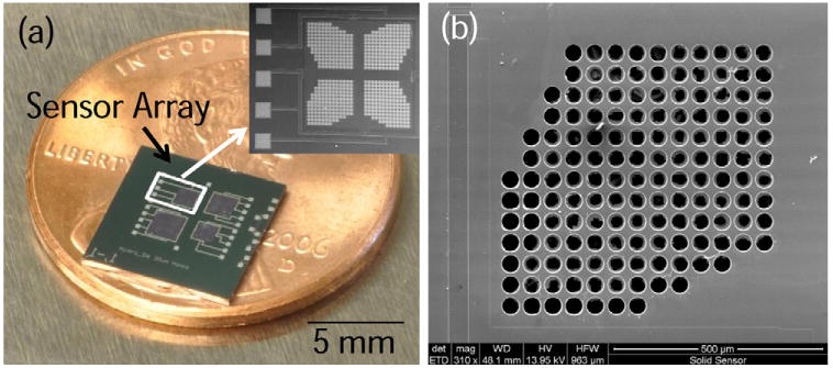
(a) Optical photograph of perforated diaphragm pressure sensor array. Inset shows a scanning electron microscope (SEM) micrograph of one of the 1 mm × 1 mm sensors. (b) SEM micrograph showing the pores (d = 40 μm) etched into one quarter of the 1 mm × 1 mm sensor diaphragm.
The 2 × 2 array measures approximately 3 mm × 5 mm and individual diaphragms were separated by a 200 μm silicon frame that was bulk etched using KOH from the backside. The 2 × 2 sensor array platform is intended to be used not only with one particular hydrogel but with numerous types of hydrogels simultaneously. By detecting multiple analytes at once additional information can be derived about the system and cross dependencies and/or sensitivities between the hydrogels can be determined.
These first generation 2 × 2 arrays were chosen as a compromise between device size and total number of analytes to be detected. Although, this paper does not discuss results from chemical testing of anything but various ionic strengths of PBS solutions efforts are underway in coupling the arrays to the other smart hydrogels. These devices are eventually intended to be surgically implanted within the body for continuous real-time monitoring of the analyte concentrations, therefore smaller devices are less invasive.
A measured thickness of diaphragms was 15 ± 3 μm determined using scanning electron microscopy (SEM). Analyte diffusion pores of 10, 20, 30, and 40 μm in diameter were etched into diaphragms using deep reactive ion etching (DRIE). The pore geometry was optimized using finite element analysis and discussed in [20] and showed that stress within the piezoresistors could be increased while stresses around the pores could be minimized. Empirical bulge testing using N2 showed that the solid diaphragm sensors had slightly improved sensitivity when compared to the perforated diaphragm sensors and was likely due to the loading conditions used in test as described in [22]. Bulge testing experiments determined that the passivation layers contained 281 MPa of compressive stress and the perforated diaphragm sensors were functional with sensitivities ranging from 23 to 252 μV/V-kPa. Passivation layers (SiO2 and Si3N4) were deposited on the topside of the sensor to protect the ion implanted piezoresistors from external environmental ion diffusion. This layer also was used for masking of the DRIE micro-pores.
2.2. HPMA/DMA/TEGDMA hydrogels
The second component of the sensor assembly is the HPMA/DMA/TEGDMA hydrogel which is currently synthesized in thin sheets with thickness of 400 μm. The chemicals used for the preparation of hydrogel were obtained as follows: hydroxypropyl methacrylate (HPMA), N,N-dimethylaminoethyl methacrylate (DMA) and crosslinker tetra-ethyleneglycol dimethacrylate (TEGDMA) were purchased from Polysciences, Inc. (Warrington, PA). Initiator system containing Ammonium peroxydisulfate (APS) and N,N,N′,N′,-tetra-methylethylenediamine (TEMED), along with Delbecco's phosphate-buffered saline solution were all obtained from Sigma–Aldrich (St. Louis, MO). All the chemicals were used as received. Polyelectrolyte pH-responsive and ionic strength sensitive hydrogels containing HPMA/DMA/TEGDMA at a nominal mole ratio of 70/30/2 were synthesized via free radical crosslinking copolymerization at room temperature as in [23,24]. In brief, appropriate amounts of monomers HPMA and DMA, crosslinker TEGDMA as well as accelerator TEMED were mixed in a vial to obtain pregel solution, which was then purged with N2 gas for about 10 min. Shortly thereafter, the initiator APS was added to the pregel solution and the mixture was vortexed for about 5 s before rapidly injected into a cavity (thickness 400 ± 10 μm) between two square glass plates of surface area 64 cm2. The hydrogel slab was removed from the glass plate after approximately 4 h of reaction, then washed with PBS solution for at least 2 days to remove unreacted chemicals prior to testing. In order to speed up the cleaning process and for preconditioning, hydrogels were subjected to five swelling/deswelling cycles by varying ionic strength of PBS between 0.15 and 0.05 M before insertion into the sensor assembly.
After synthesis and initial conditioning gels were placed in a 0.15 M solution of PBS to ensure they were in a contracted state. Next the gels were laid on a glass slide (Fig. 3) in an air environment at room temperature for 60 min to improve the adhesion to the slide. The process reduced the water content of the gel through evaporation and made the gels easier to cut using a surgical scalpel. The gels were then trimmed into squares under a microscope with dimensions roughly 1 mm × 1 mm, 1.25 mm × 1.25 mm and 1.5 mm × 1.5 mm and placed into the sensors' backside KOH etched cavity.
Fig. 3.
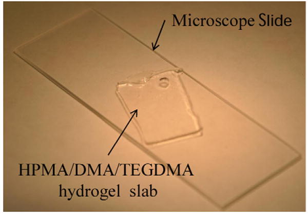
Photograph of the HPMA/DMA/TEGDMA hydrogel on glass slide before sample cutting and insertion into the sensors.
2.3. Backing plates
The final part of the sensor assembly is the backing plate used to hold the hydrogel in contact with the pressure sensing diaphragm. Two configurations of this component were fabricated, one for the solid diaphragm, and the other for perforated diaphragm sensors. The sensors with solid silicon diaphragms require that the diffusion pores are fabricated directly into the backing plate, while perforated diaphragm sensors allow analyte diffusion into the hydrogel cavity directly through the diaphragm. The backing plates for the solid diaphragm sensors were fabricated with pores that ranged in size from 100 to 175 μm in diameter in 25 μm increments with a 200 μm pitch. These pore dimensions were used because they were easily micro-machined using DRIE (Bosch process) in 5 mm × 5 mm arrays (Fig. 4). The backing plates were the same thickness of the wafer (400 ± 15 μm) and covered the backside of all four sensors simultaneously. Backing plates for the perforated diaphragm sensors were made using the same wafers without any pores. The backing plates were singulated into 8 mm × 8 mm using Disco (Tokyo, Japan) dicing saw and attached to the sensors using silicone adhesive (NuSil MED-4211, Carpinteria, CA, USA) and allowed to cure for 48 h before testing.
Fig. 4.
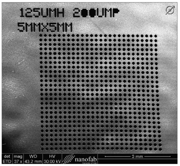
SEM micrograph of the deep reactive ion etched (DRIE) porous backing plate (5 mm × 5 mm) with pore diameter of 125 μm and a pitch of 200 μm. Waviness of the surface is due to not being completely planar since this particular wafer was thinned using KOH. The backing plates used for testing do not exhibit this characteristic.
2.4. Wire bonding
Each sensor array has a total of 20 electrical inputs/outputs, 4 for each sensor which include: Vin, Gnd, Vout+, Vout−. To interface the 2 × 2 arrays a custom designed FR-4 printed circuit board (PCB) was fabricated with a total of 100 bond pads. After cleaning the sensors and PCB using isopropyl alcohol and deionized water sensors were ultrasonically wedge wire bonded using a semi-automatic wire bonding machine (West.Bond, Inc., Anaheim, CA). Insulted gold wires (d = 50 μm) were employed because they add another layer protection needed for solution testing. Utmost care was taken not to fracture sensor diaphragms during wire bonding since they are thin (∼15 μm) and can easily break.
2.5. Sensor passivation
The sensor assembly requires a long term stable encapsulation to avoid device deterioration in the harsh physiological testing environment. The passivation layer acts as a dielectric barrier to isolate the metal electrical traces of sensor array from the wet external environment. Ideally, the encapsulation material needs to be thin (<5 μm), conformal, pinhole free, low stress and deposited at near room temperature, since the entire diaphragms are coated it is important the passivation does not alter the mechanical properties of the diaphragms and hence the electrical output. Chemical vapor deposited (CVD) parylene (para-xylylene) thin films were used because they can deposited at room temperature, and the coating process involves no curing, solvents, or additives. Consequently, the concerns associated with thermal piezoresistor diffusion, diaphragm stress, and contamination is minimized. Parylene also exhibits a low permeability to moisture make it an ideal choice for such applications. After assembly, the sensor, wiring and PCB are coated with parylene C (poly para-xylylene) as shown in Fig. 5. A Para tech Coating, LabTop 3000 (Aliso Viejo, CA) system is used vaporize the parylene solid dimer at 150 °C then pyrolize it into stable monomeric diradical, para-xylylene at 680 °C. These monomers then enter the deposition chamber at room temperature and get adsorbed and polymerized on the sample simultaneously. A monitor sample is also coated along with the sensors and was used to verify the encapsulation layer thickness as being approximately 3 ± 0.5 μm. An added benefit of this passivation process is it also mechanically enhances the strength the wire bonds need for the repeated chemical testing.
Fig. 5.
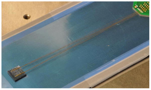
Photograph of topside of a solid diaphragm sensor assembly with hydrogel inserted and mounted to a perforated backing plate (out of view). Wire bonding was performed using gold insulated wire (d = 50 μm). The entire assembly, wires, and PCB are ready for parylene deposition.
2.6. Testing apparatus
For each sensor array a 26 pin latch connector is soldered to the custom PCB and connected to ribbon cable that interfaces a data acquisition unit (Agilent Technologies, Inc., 34970A, Santa Clara, CA) through a 20 channel multiplexer (Agilent technologies, Inc., 34901A, Santa Clara, CA). A high accuracy DC power supply (B&K Precision Corporation, 1621, Yorba Linda, CA) was used to apply the 1V input voltage. The data acquisition unit is connected to a personal computer using a GPIB cable to monitor and record data. “Benchlink Data logger 3” software (Agilent Technologies, Inc., 34825A, Santa Clara, CA) was used to record and plot real-time test data. The testing apparatus is shown in Fig. 6.
Fig. 6.
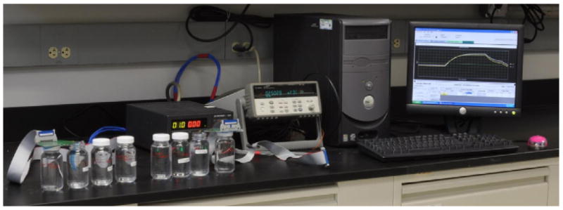
Photograph of the testing apparatus used to determine sensor electrical output characteristics. The sensors were placed in solutions of varying ionic strength and the voltage output was simultaneously measured.
3. Experimental methods
The hydrogel swelling pressure was measured in relation to changes of ionic strength of PBS solutions. These initial tests are used to qualify the sensor designs and provide proof of concept for the perforated diaphragm sensors. Therefore, sensors of the two varying designs were subjected to identical experimental conditions and compared. Solution tests were conducted using phosphate buffer solution (PBS) with a human physiological pH value of 7.4 and ranging in ionic strength from 0.025 to 0.15 M. PBS solution with 0.15 M was purchased from Sigma–Aldrich (St. Louis, MO, USA) made of NaH2PO4, HCl, and NaCl and diluted with deionized water to create solutions with reduced ionic strength. The solutions were mixed in 100 ml plastic experimental bottles then sensor assemblies were placed directly into the bottles at room temperature without additional agitation (Fig. 7).
Fig. 7.
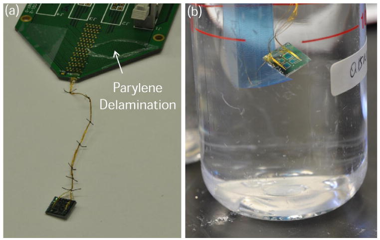
(a) Photographs of sensor assembly post-parylene deposition with insulated wires sutured together for additional strength and placed in (b) experimental bottle for chemical testing of ionic strength. The parylene delamination was caused by tape adhesion testing.
4. Results and discussion
4.1. Sensitivity
Sensitivity testing was performed to determine how well sensor arrays can discriminate between solutions of varying ionic strengths. These measurements were taken after the initial hydrogel conditioning cycles. Fig. 8 shows sensor voltage output with respect to change ionic strength of the PBS solution for the two different sensor designs. The perforated diaphragm sensors have pore size of 40 μm and the perforated backing plate sensors have pores of 175 μm, with pitches of 200 and 50 μm, respectively. The perforated diaphragms have an open area of approximately 64% while the backing plates have an open area of 60%. The diaphragms are much thinner (15 μm) than the backing plates (400 μm) which may increase diffusion rate into the hydrogel cavity and hence the response time but at equilibrium should not affect the total hydrogel pressure generation or sensor sensitivity. The sensors were allowed to equilibrate in 0.15 M PBS for 1 h then the arrays were placed into the solution containing 0.025 M PBS causing the hydrogels to swell and subsequent increase in voltage output. The ionic concentrations were then reversibly decreased and the final step the solution was then returned to its initial concentration of 0.15 M.
Fig. 8.
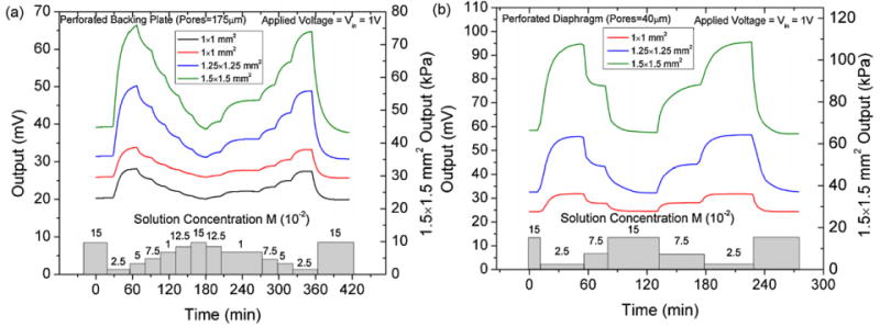
Output data used for the calculation of sensitivity for the (a) solid and (b) perforated diaphragm pressure sensors. The perforated diaphragm sensors have a higher sensitivity and larger output for identical environmental testing conditions.
The sensors offsets ranged between 21 and 35 mV for all sensors tested which indicates that the hydrogels may have slightly preloaded the diaphragm up to 15 kPa when inserted into to cavity. These values agree with offsets measured in previous characterization experiments presented in [22]. When the sensors are placed in the 0.15 M PBS solution and at equilibrium the sensors output is stable with noise levels on the order of 1 × 10⁻⁶ V. The diaphragm size was shown to have a prominent impact on the sensitivity of individual sensors in the array. As expected the largest diaphragm sensors have the highest sensitivity due to increased stresses developed in the piezoresistors. Comparing the sensitivities of the two designs at both 0.025 and 0.075 M we can see that for the same experimental conditions the output of the perforated diaphragms sensors is higher as shown in Fig. 9.
Fig. 9.
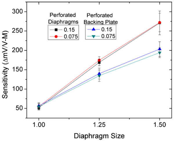
Comparison of sensitivities for perforated diaphragm and solid diaphragm sensors placed in 0.025 and 0.075 M PBS solutions. Perforated diaphragm sensors were more sensitive for all sensors in the array.
The increased sensitivity is due to higher stress induced in the piezoresistors for a particular hydrogel swelling pressure. This is due to a combination of effects. First, the perforations are defined in such a way as to maximize stress within the diaphragm [20]. Additionally, the forces and hence stress exhibited on the diaphragm from loading vary between the two designs. Assuming the hydrogel does not exude through the pores the same total force is applied to the two different diaphragms. This force is determined by swelling pressure times the diaphragm area. For the perforated diaphragm sensors, stresses experienced by the piezoresistors are higher, since there is less diaphragm material to resist the hydrogel swelling pressure. Hence, the perforated diaphragm design experiences higher stress and therefore increased sensitivity. In this scenario the highest forces are witnessed by the diaphragm with largest pores. The actual amount of deformation of the gel through the pores is difficult to estimate and should be studied empirically since the hydrogel mechanical properties can vary significantly.
4.2. Response time
The sensor response time is influenced by a number of factors including analyte diffusion and hydrogel kinetics. In order for the HPMA/DMA/TEGDMA hydrogels to swell/contract water must be absorbed or released by the gel. This is effectively controlled by the chemical potential of the water which is dependent on ionic strength. At lower ionic strength the water has a higher chemical potential and the gels swell. Therefore, the internal sensor cavity where the hydrogel is located requires the exchange of the analytes with the external environment. This process is complicated by the fact that multiple mass transfer mechanisms are occurring concurrently.
Initial preconditioning of the sensors was performed by alternating between the highest (0.15 M) and lowest (0.025 M) ionic concentrations for several cycles. This process step is performed to allow the internal structure to reach steady state conditions prior to sensitivity testing [25]. The arrays output voltage was measured during the preconditioning cycles to measure the swelling pressure shown in Fig. 10. This data, representative of all sensors, was taken using the perforated diaphragm 1 mm × 1 mm pressure sensor with diaphragm pore sizes of 40 μm. During the first operation, the hydrogel sensor often showed poor repeat accuracy and a slight drift of the sensor parameters. It is shown that the first initial couple of cycles of have different response characteristics then subsequent cycles. We found that the repeatability of the sensor response can be significantly increased by performing the conditioning cycles. In general, the conditioning process was complete after 3–5 swelling-contracting cycles.
Fig. 10.
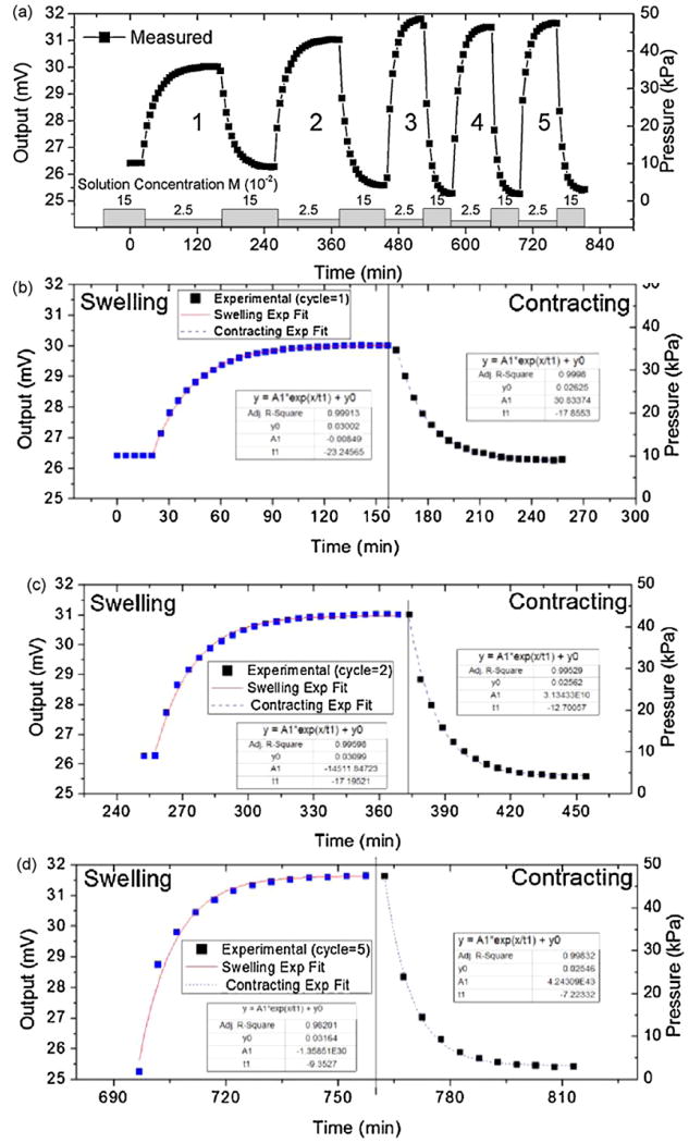
(a) Plot showing the sensor response during the first five cycles of testing between 0.15 and 0.025 M PBS solution concentrations. Exponential fits of (b) cycle 1 (c) cycle 2 and (d) cycle 5 for the swelling and contracting half cycles. Data shows the initial cycles have the smallest and slowest response.
Specifically, for the 1 mm × 1 mm sensor the first cycle had the slowest response and the lowest swelling pressure of approximately 30 kPa. The second cycle had an improved pressure output of 40 kPa and a slightly faster response. After the second cycle the measured swelling pressure and response time became more reversible and repeatable with an output pressure of roughly 45 kPa. This phenomenon is attributed to the fact that the gels are initially in a partially dry contracted state with little absorbed water. In this state the swelling process is governed by the analyte and polymer chain mobility. The dry contracted state of the hydrogel has reduced diffusion channels size which consequently slows diffusion into the gel. Before testing molecular chains are more tightly bound with a higher crosslinking density. It has been previously reported that the diffusivity of analytes decreases as: the crosslinking density increases, size of the analyte increases, and the volume fraction of water within the gel decreases [26]. During the first few cycles the hydrogel absorbs water becoming better situated inside the sensors cavity. This is shown by the reduced baseline value of the output signal. As the hydrogel is cycled the polymer chains are molecularly reconfigured and response is improved. By fitting the output voltage signal to the exponential growth function described in equation 1 we can quantify the swelling (τswelling) and contracting (τcontracting) time constants.
| (1) |
Fig. 11 compares the time constants (τ) calculated using the exponential fit for the swelling and contacting of the first five cycles for both sensor types. Results show that the hydrogels initially take more than two times as long to reach equilibrium when comparing the cycle = 1 to cycles ≥3.
Fig. 11.
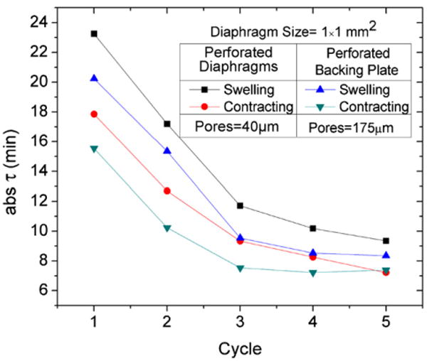
Plot of the calculated time constants (τ) with respect to the first 5 cycles for the two sensor types. The sensors response time shows significant improvement after an initial conditioning period. Response times for the various sensor types are similar.
When comparing the response time between sensors with perforated diaphragms (pore diameter = 40 μm) or porous backing plates (pore diameter = 175 μm), sensors with porous backing plates had a slightly lower τswelling and τcontracting. This means that the sensor reaches equilibrium faster and is likely due to the larger pores allowing a higher diffusion rate of analytes in and out of the hydrogel cavity improving hydrogel swelling response. Also according to Fig. 12, we determined that the contracting time constants were consistently less than that of swelling for both sensors with perforated diaphragms and backing plates. This is likely due to an imbalance of mechanical forces exhibited on the hydrogel from the piezoresistive diaphragm during testing. During swelling the hydrogel volume expands filling all available free space in the sensor cavity then begins to deflect the piezoresistive diaphragm. At equilibrium the swelling pressure of the hydrogel is equal to the pressure applied by the piezoresistive diaphragm. During the contraction the piezoresistive diaphragm applies additional mechanical pressure aiding in the out diffusion of water from the hydrogel. The increased hydrogel loading during contraction improves the response time during contraction half cycle.
Fig. 12.
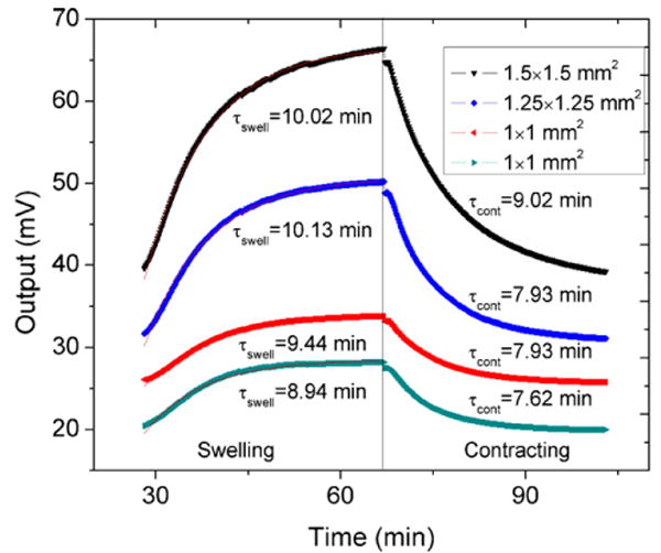
Swelling and contracting time constants calculated for the various sized perforated diaphragm sensors within the array after conditioning. The sensors were cycled from 0.15 to 0.025 M PBS and the smaller diaphragms had faster response.
Fig. 12 compares response times of the various sized sensors within the sensor array. We found that the 1 mm × 1 mm sensors have decreased time constants and faster response than the larger 1.25 mm × 1.25 mm and 1.5 mm × 1.5 mm sensors even though the hydrogel thickness (∼400 μm) is the same for each sensor. This is likely due to hydrogel loading characteristics. The larger diaphragms are more compliant and sensitive to minute increases in hydrogel swelling pressure while the smaller sensors diaphragms are more rigid. Hence, it takes longer to reach equilibrium for the larger sensors, increasing the swelling and contracting time constants. Another reason may be that the larger sensors use hydrogels which have a reduced surface to volume ratio which might lead to decreased analyte diffusion rates.
Although the response time (τ90 ∼20 min) is still relatively slow, and therefore, suboptimal for many real-world applications we are investigating a number of methods to improve the sensor response time including:
Directly modifying hydrogel chemistry to reduce the swelling time and increase swelling pressures.
Use of thinner hydrogels will increase surface area and the surface to volume ratio of the hydrogels allowing analyte to diffuse more quickly into the gel ultimately reducing the sensor response time by increasing swelling rate.
Create sensors that have diffusion pores located in both the diaphragm and backing plate to increase analyte diffusion rate into the gel.
Creating porous hydrogels (or hydrogel beads) with channels that allow rapid analyte diffusion.
4.3. Stability
Sensor lifetimes of over 400 h in PBS buffer solution at 23 °C were observed, but the baseline offset started drifting after approximately 50 h. Generally, the sensors output drifts within a few days of testing due to the premature failure of the encapsulation which can be improved by using a thicker parylene coating, improved deposition parameters, or a new encapsulation material. We observed that on two sensors the parylene passivation on the wire bonds was compromised, indicated by the depositions of salts on the metallization. This indicates that the PBS solution is likely diffusing through the parylene to the metallization. When analyzing the data of the sensor which lasted the longest we learned that the sensor sensitivity remained stable (∼135 mV/V-M) while only the baseline drifted. Originally the sensor output was roughly 30 mV but after 200 h of testing the sensor offset drifted to >50 mV and stabilized. Presumably this was due to one or more of the wire bonds being compromised and the resistance was modified on one leg of the Wheatstone bridge creating an imbalance leading to a drifting baseline. Future experiments are planned to validate that hypothesis and to improve passivation performance (Fig. 13).
Fig. 13.
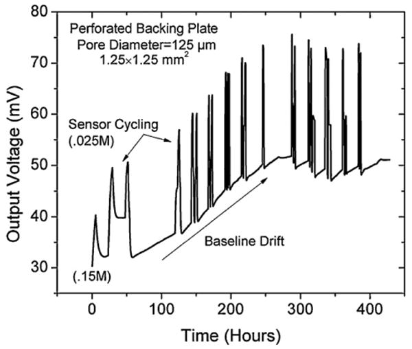
Plot illustrating the long term stability of the 1.25 mm × 1.25 mm perforated backing plate sensor with 125 μm pores. The sensor was cycled between 0.15 and 0.025 M PBS concentrations and although the sensor responded to changes in ionic strength for ∼400 h it the baseline drifted significantly.
5. Conclusions
We have developed two types of sensor arrays used for the detection of hydrogel swelling pressures, one version with perforation, acting as analyte diffusion pores etched directly into the piezoresistive diaphragm, the other with pores etched into the backing plate while using a solid diaphragm. Hydrogels (HPMA/DMA/TEGDMA) which swell in response to changes in ionic strength of PBS solution were integrated into the sensor chips and used in the characterization of the sensors. The sensors were placed into solutions of ionic strengths ranging from 0.025 to 0.15 M. Sensors with pores directly etched into the diaphragm exhibit higher sensitivity. Initial conditioning steps were necessary to precondition the hydrogel within the sensor and stabilize response. The sensor response was fitted to a first order exponential growth function for the swelling and contracting half cycles and τswelling > τcontracting was observed for all sensors. The steady state response times of the two sensor version were comparable and improved after 3–5 cycles with values of approximately 9 and 7min for τswelling and τcontracting. To our knowledge this is the first paper that gives test results for a perforated diaphragm pressure sensor array for the detection of hydrogel swelling pressure used in chemical analysis. We are confident that we can improve long term sensor stability through the optimization of the passivation process, and this sensor design offers a universal platform capable of detecting the swelling pressure of various stimuli-responsive hydrogels. We have demonstrated “proof of concept” of a sensor design that incorporates perforations into a piezoresistive diaphragm for the diffusion of analytes. This design modification was shown to improve sensitivity. In the future experiments are planned to investigate the effect of diaphragm pore size directly on response time and sensitivity.
Acknowledgments
This work is supported by NIH R21 grant #: 5R21EB008571-02.
Biographies
Michael P. Orthner received his MS degree from University of Utah in 2006 and developed a low pressure chemical vapor deposition (LPCVD) system for the epitaxial growth of 3C-SiC on Si. Presently, he is a doctoral candidate in electrical engineering focusing his research on development of hydrogel based sensors for metabolic monitoring applications. He was awarded the F.M. Becket summer fellowship from the Electrochemical Society in 2007. In 2008 and 2009, he was awarded a scholarship from the Society of Vacuum Coaters (SVC). He currently has 3 patents pending, and is an author on more than 10 journal articles and conference proceedings.
Genyao Lin is a graduate student in Materials Science & Engineering at the University of Utah. He received his BS degree in polymer science & engineering in 2006 from Zhejiang University of Technology, Hangzhou, PR China. His research areas of interest include synthesis and testing of stimuli-responsive hydrogels and polymeric biomaterials.
Mahendernath Avula is a graduate student in the Department of Mechanical Engineering at the University of Utah. He received his bachelors degree in mechatronics in 2006 from Jawaharlal Nehru Technological University, India. He is currently working on the use of stimuli-responsive hydrogels based microsensors for continuous metabolic monitoring applications.
Sebastian Buetefisch received his Diploma in mechanical engineering from the Technical University of Braunschweig, Germany, in 1997. Currently he is employed at the Institute for Microtechnology at the Physikalisch Technische Braunschweig, Braunschweig, Germany. His research interests are in the development and fabrication of micro-grippers, micro-mechanical actuators, low-g acceleration sensors, tuning fork gyroscopes and high resolution three-dimensional tactile force sensors.
Jules Magda is an associate professor in chemical engineering and in materials science & engineering at the University of Utah. He received his BS in chemical engineering in 1979 from Stanford University, and his PhD in chemical engineering and materials science in 1986 from the University of Minnesota in Minneapolis. His areas of interest include stimuli-responsive hydrogels and biomedical sensors for treatment of diabetes and obesity.
Loren W. Rieth received his BS degree in materials science from The Johns-Hopkins University, Baltimore, MD, in 1994. He received his PhD in materials science and engineering from the University of Florida, Gainesville, FL, in 2001. From 2001 to 2003, he was a postdoctoral research associate at the University of Utah, Salt Lake City, UT, and continued on at the University of Utah as a research assistant professor in materials science (2003–2005), and electrical and computer engineering (2004–present). His research is focused on deposition and characterization of thin film materials for sensors (chemical, physical, and biological), MEMS, BioMEMS, and energy production.
Florian Solzbacher is director of Microsystems Laboratory, director of the Utah Nanofabrication Laboratory at the University of Utah, co-director of the Utah Nanotechnology Institute, president of Blackrock Microsystems and holds faculty appointments in electrical and computer engineering, materials science and bioengineering. His research focuses on harsh environment microsystems and materials, including implantable, wireless microsystems for biomedical and healthcare applications, but also high temperature and harsh environment compatible micro-sensors. Prof. Solzbacher received his MSc EE from the Technical University Berlin in 1997 and his PhD from the Technical University Ilmenau in 2003. He is co-founder of several companies such as Blackrock Microsystems, First Sensor Technology and NFocus. He was a board member and Chairman of the German Association for Sensor Technology AMA from 2001 until 2009, and serves on a number of company and public private partnership advisory boards. He is author of over 100 journal and conference publications, 5 book chapters and 16 pending patents.
References
- 1.Ming L, Baldi A, Pan T, Yuandong G, Siegel RA, Ziaie B. A hydrogel-based wireless chemical sensor. Micro Electro Mechanical Systems; 17th IEEE International Conference on. (MEMS); 2004; 2004. pp. 391–394. [Google Scholar]
- 2.Miyata T, Asami N, Uragami T. Preparation of an antigen-sensitive hydrogel using antigen–antibody bindings. Macromolecules. 1999;32:2082–2084. [Google Scholar]
- 3.Miyata T, Uragami T, Nakamae K. Biomolecule-sensitive hydrogels. Advanced Drug Delivery Reviews. 2002;54:79–98. doi: 10.1016/s0169-409x(01)00241-1. [DOI] [PubMed] [Google Scholar]
- 4.Guenther M, Kuckling D, Corten C, Gerlach G, Sorber J, Suchaneck G, Arndt KF. Chemical sensors based on multiresponsive block copolymer hydrogels. Sensors and Actuators B: Chemical. 2007;126:97–106. [Google Scholar]
- 5.Cong J, Zhang X, Chen K, Xu J. Fiber optic Bragg grating sensor based on hydrogels for measuring salinity. Sensors and Actuators B: Chemical. 2002;87:487–490. [Google Scholar]
- 6.Guiseppi-Elie A, Brahim S, Slaughter G, Ward KR. Design of a subcutaneous implantable biochip for monitoring of glucose and lactate. Sensors Journal, IEEE. 2005;5:345–355. [Google Scholar]
- 7.Scheller FW, Wollenberger U, Warsinke A, Lisdat F. Research and development in biosensors. Current Opinion in Biotechnology. 2001;12:35–40. doi: 10.1016/s0958-1669(00)00169-5. [DOI] [PubMed] [Google Scholar]
- 8.Richter A, Bund A, Keller M, Arndt KF. Characterization of a microgravimetric sensor based on pH sensitive hydrogels. Sensors and Actuators B: Chemical. 2004;99:579–585. [Google Scholar]
- 9.Gerlach G, Guenther M, Suchaneck G, Sorber J, Arndt KF, Richter A. Application of sensitive hydrogels in chemical and pH sensors. Macromolecular Symposia. 2004;210:403–410. [Google Scholar]
- 10.Gerlach G, Guenther M, Sorber J, Suchaneck G, Arndt KF, Richter A. Chemical and pH sensors based on the swelling behavior of hydrogels. Sensors and Actuators B: Chemical. 2005;111:555–561. [Google Scholar]
- 11.Guenther M, Gerlach G, Kuckling D, Kretschmer K, Corten C, Weber J, Sorber J, Suchaneck G, Arndt KF. Chemical sensors based on temperature-responsive hydrogels. In: Inaudi D, Ecke W, Culshaw B, Peters KJ, Udd E, editors. Smart Structures and Materials 2006: Smart Sensor Monitoring Systems and Applications. Vol. 6167. 2006. p. 61670T. [Google Scholar]
- 12.Thong Trinh Q, Gerlach G, Sorber J, Arndt KF. Hydrogel-based piezoresistive pH sensors: design, simulation and output characteristics. Sensors and Actuators B: Chemical. 2006;117:17–26. [Google Scholar]
- 13.Sorber J, Steiner G, Schulz V, Guenther M, Gerlach G, Salzer R, Arndt KF. Hydrogel-based piezoresistive pH sensors: investigations using FT-IR attenuated total reflection spectroscopic imaging. Analytical Chemistry. 2008;80:2957–2962. doi: 10.1021/ac702598n. [DOI] [PubMed] [Google Scholar]
- 14.Richter A, Paschew G, Klatt S, Lienig J, Arndt KF, Adler HJP. Review on hydrogel-based pH sensors and microsensors. Sensors. 2008;8:561–581. doi: 10.3390/s8010561. [DOI] [PMC free article] [PubMed] [Google Scholar]
- 15.Herber S, Borner J, Olthuis W, Bergveld P, Van Den Berg A. Transducers. Vol. 2. Seoul, South Korea: 2005. A micro CO2 gas sensor based on sensing of pH-sensitive hydrogel swelling by means of a pressure sensor; pp. 1146–1149. [DOI] [PubMed] [Google Scholar]
- 16.Herber S, Bomer J, Olthuis W, Bergveld P, Berg Avd. A miniaturized carbon dioxide gas sensor based on sensing of pH-sensitive hydrogel swelling with a pressure sensor. Biomedical Microdevices. 2005;7:197–204. doi: 10.1007/s10544-005-3026-5. [DOI] [PubMed] [Google Scholar]
- 17.Herber S, Olthuis W, Bergveld P, van den Berg A. Exploitation of a pH-sensitive hydrogel disk for CO2 detection. Sensors and Actuators B: Chemical. 2004;103:284–289. [Google Scholar]
- 18.Herber S, Olthuis W, Bergveld P. A swelling hydrogel-based PCO2 sensor. Sensors and Actuators B: Chemical. 2003;91:378–382. [Google Scholar]
- 19.ter Steege R, Herber S, Olthuis W, Bergveld P, van den Berg A, Kolkman J. Assessment of a new prototype hydrogel CO2 sensor; comparison with air tonometry. Journal of Clinical Monitoring and Computing. 2007;21:83–90. doi: 10.1007/s10877-006-9060-x. [DOI] [PubMed] [Google Scholar]
- 20.Orthner M, Rieth L, Buetefisch S, Solzbacher F. Design, simulation and optimization of a novel piezoresistive pressure sensor with stress sensitive perforated diaphragm for wet sensing and hydrogel applications. IEEE Sensors. submitted for publication. [Google Scholar]
- 21.Lin G, Chang S, Kuo CH, Magda J, Solzbacher F. Free swelling and confined smart hydrogels for applications in chemomechanical sensors for physiological monitoring. Sensors and Actuators B: Chemical. 2008:186–195. doi: 10.1016/j.snb.2008.11.001. [DOI] [PMC free article] [PubMed] [Google Scholar]
- 22.Orthner M, Rieth L, Buetefisch S, Solzbacher F. Development, fabrication, and characterization of a piezoresistive pressure sensors using perforated diaphragms for chemical sensing. Sensors and Actuators A: Physical. doi: 10.1016/j.sna.2010.05.023. Submitted to Sensors and Actuators A and under external review. [DOI] [PMC free article] [PubMed] [Google Scholar]
- 23.Jung DY, Magda JJ, Han IS. Catalase effects on glucose-sensitive hydrogels. Macromolecules. 2000;33:3332–3336. [Google Scholar]
- 24.Han IS, Han MH, Kim J, Lew S, Lee YJ, Horkay F, Magda JJ. Constant-volume hydrogel osmometer: a new device concept for miniature biosensors. Biomacromolecules. 2002;3:1271–1275. doi: 10.1021/bm0255894. [DOI] [PubMed] [Google Scholar]
- 25.Johnson BD, Beebe DJ, Crone WC. Effects of swelling on the mechanical properties of a pH-sensitive hydrogel for use in microfluidic devices. Materials Science and Engineering C. 2004;24:575–581. [Google Scholar]
- 26.Amsden B. Solute diffusion within hydrogels. Mechanisms and models. Macro-molecules. 1998;31:8382–8395. [Google Scholar]


