Abstract
Background
Magnetic Resonance Imaging (MRI) guided prostate interventions have been introduced to enhance the cancer detection. For accurate needle positioning, in-bore operated robotic systems have been developed and optimal use of the confined in-bore space become a critical engineering challenge.
Methods
As preliminary evaluation of our prostate intervention robot, we conducted a workspace design analysis using a new evaluation method that we developed for in-bore operated robots for transperineal prostate interventions, and an MRI compatibility study.
Results
The workspace analysis resulted in the effective workspace (VW) of 0.32, which is greater than that of our early prototype despite that the current robot is approximately 50% larger than the early prototype in sectional space. The MRI compatibility study resulted in less than 15% signal-to-noise ratio (SNR) reduction.
Conclusions
The new workspace evaluation method quantifies the workspace utilization of the in-bore operated robots for MRI-guided transperineal prostate interventions, providing a useful tool for evaluation and new robot design. The robot creates insignificant electromagnetic noise during typical prostate imaging sequences.
Keywords: medical robotics, workspace design analysis, MRI-compatible robot, transperineal prostate intervention
Introduction
Magnetic resonance imaging (MRI) has been sought as an alternative tool to transrectal ultrasound (TRUS) for image guidance for the prostate biopsy. MRI has high sensitivity for detecting prostate tumor due to excellent soft tissue contrast, high spatial resolution, and multi-planar volumetric imaging capabilities (1–4). MRI-guided prostate biopsy was first demonstrated by D’Amico et al (5, 6) in a specially-designed 0.5T open-MRI scanner, followed by other researchers in conventional closed-bore scanners that provides greater image quality and wider availability of scanners (7–11). To support needle placement in the limited workspace inside the closed-bore MRI, a number of MRI-compatible robots that are operated inside the closed-bore high-field MRI have been introduced for transperineal MRI-guided prostate intervention. Stoianovici reported phantom experiments with a pneumatically actuated robot for transperineal prostate intervention (12). Fisher reported the development of a pneumatically actuated needle guide robot for transperineal needle placement (13), which is an early ‘proof-of-concept’ robot of our current robot development. Goldenberg reported phantom studies and MRI compatibility tests with an ultrasonic motor actuated robotic system (14), and van den Bosch reported a pneumatic robot system that using tapping insertion (15). More recently, Yakar reported a pneumatically actuated MR-compatible robot for prostate biopsy guidance (16), and Su reported a real-time MRI-guided needle placement robot with fiber optic force sensing (17).
These robotic devices, however, seem to lack a design consideration on securing space for a clinician to access the patient inside the bore. Even for robots equipped with needle insertion and tissue sampling mechanisms, it is crucial to secure safe access of clinicians to the patient in the bore from safety point of view. While many of the requirements have been discussed extensively in the literature, there has been no report on workspace-oriented design of MRI-compatible device for prostate biopsy guidance, due to the apparent lack of quantitative design parameter for the clinician’s workspace. Without a quantitative workspace parameter, researchers had to be satisfied with using intuition in analyzing workspace requirements, often leading to limited clinical utility and safety of the resulting robots. Therefore, there is a need for a method to design a robotic device that maximizes the workspace for clinicians to coexist with a robot within a bore based on a quantitative workspace evaluation.
This paper reports our robotic device for MRI-guided transperineal prostate biopsy with emphasis on optimal use of in-bore workspace. We introduce a new workspace analysis method tailored to quantitatively validate “effective workspaces”, a free space that can be utilized for procedural tasks by a clinician in an MRI bore with such in-bore operated robotic devices based on actual dimensions of a MRI scanner and medium build man, and compared it with our early prototype (13) for transperineal prostate interventions. The effective workspace cannot be measured directly, because it is not always equal to a free space in the bore; certain areas of the free space cannot be reached by the clinician due to the existence of obstacles e.g. the patient’s body, robot and auxiliary objects, such as leg holders, imaging coils, drapes, etc. In addition, we conducted an image-based validation study to investigate if the MRI-compatible robot meets the fundamental requirement of such robots to have minimum impact on image quality.
Materials and Methods
Current Needle Guide Robot
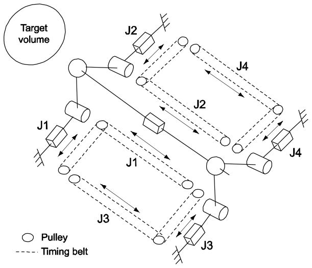
We developed a pneumatically actuated robotic intervention system with design emphases on optimal use of in-bore workspace of a closed-bore MRI scanner employing parallel kinematic structure and modular system design for greater clinical adaptability (18, 19). In order to access to entire volume of prostate via perineum without interference with pubic arch and urethra, we selected 4-degrees-of-freedom (DOF) kinematic design that can provide remote-center-of-motion (RCM) manipulation from target volume as a minimum needle placement requirement. In order to maximize the use of dead space i.e. “under-the-leg” space, and to obtain the maximum access space above the robot, a pyramid-shape kinematic structure was selected. To accommodate a long needle driving range and to satisfy the required manipulation, a 4-DOF parallel kinematic structure that has a coupled two planar manipulation with ball joints was configured shown as Fig. 1.
Fig. 1.
Equivalent kinematic diagram of the robot. Bar, cylinder and sphere represent prismatic, revolute, and ball joint respectively. The prismatic joints are actuated and others are passive. Needle is located on the needle platform and is inserted through the front (near target volume) ball joint
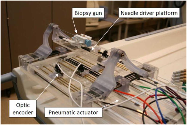
The robot was fabricated with non-ferrous materials. Most material is fully MRI compatible plastic and a minimal amount of non-ferrous metal that was selected to avoid heating and eddy currents to disturb field homogeneity. The prismatic manipulation of four pneumatic actuators are transmitted to the two planar manipulation via timing-belts (MXL type, trapezoidal teeth, urethane body, Kevlar core, 1/8″ width, 0.08″ pitch) and pulleys (MXL type, 1/8″ width, 0.08″ pitch, aluminum body, brass setscrew). Cast acrylic machined by laser cutter is used for most of the robot structure and some parts are fabricated from commercial Stereolithography Apparatus (SLA) rapid-prototype service using Acura® 60 plastic (Acu-Cast Technologies, LLC., Lawrenceburg, TN). Plastic ball joints, bearings, and bushings are all off-the-shelf parts (Igus Inc., East Providence, RI). Non-ferromagnetic brass (alloy 260 and 360) and anodized aluminum (alloy 6061) shafts were also used. Fig. 2 shows the fabricated robot.
Fig. 2.
A photo of fabricated pneumatically actuated 4-DOF robot for MRI-guided transperineal prostate needle placement. A semi-automatic biopsy gun is located on needle platform
The controller described in (13) is used for the current robot. It previously operated inside of the scanner room, approximately 3 m from the 3T scanner without functional difficulties or significant image quality degradation. The controller that is in the electromagnetic interference shielded enclosure contains the embedded Linux PC providing low-level servo control, the piezoelectric valves, and the fiber-optic Ethernet converter. Connections to the robot include the air hose, the encoder cable. The controller is powered through the grounded patch panel, which is designed for such connections and data communication is enabled via fiber-optic Ethernet. 3D Slicer (www.slicer.org) surgical navigation software serves as a user interface with the robot. The navigation software is running on a Linux-based workstation in the scanner’s console room, which is connected to the robot via Ethernet.
In the previous study (18), we reported the kinematics detail and the accuracy of the robot. The key parameters are shown in Table 1.
Table 1.
Kinematic and accuracy specifications of the current robot
| Range of motion | Actuator | 80 mm |
| Global 1 | 50 mm | |
| Angling 1 | 9.46 degree | |
|
| ||
| Accuracy | Actuator | 0.2 mm |
| Targeting 2 | < 0.5 mm | |
due to the complex workspace geometry, ranges are set as a target circle instead of maximum ranges.
within the needle insertion range of 150 mm.
Validation Studies
Effective Workspace
Definition of effective workspace
Fig. 3 illustrates a typical configuration of a patient and a robot in a closed-bore MRI scanner for a transperineal prostate intervention, where the robot is placed between the legs of the patient lying on the scanner’s table in lithotomy position. We define a right-handed coordinate system so that x, y, and z axis orients to the right, anterior and superior direction of the patient, respectively, with its origin at the iso-center of the MRI scanner. The clinician may access the patient from the opening of the bore on the inferior side of the patient (or negative z in the scanner’s coordinate system) to perform procedural tasks, such as firing a preloaded biopsy needle. In our evaluation, we assume that only a patient and a robotic device are placed in the bore. The space in the bore can be classified into the followings:
Fig. 3.
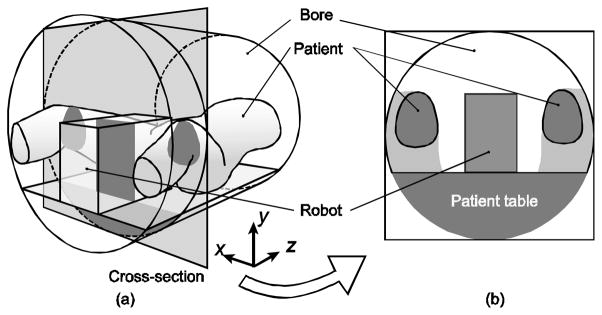
The typical patient and robot configuration for transperineal MRI-guided prostate intervention (a) and its cross-section (b)
Total bore space (VB): The volume of the total space in the bore.
Free space (VF): The volume of the space that is not occupied by any object (i.e. robotic device, patient body)
Effective workspace (VW): The volume of the free space that is utilized for procedural tasks by the clinician.
Dead space (VD): The volume of the free space that is not accessible by the clinician.
Space occupied by the robotic device (VR): The volume occupied by the robotic device.
Space occupied by the subject (VS): The volume occupied by the patient.
Since there are no overlaps among VF, VR and VS, the volume of the total bore space VB can be calculated as a sum of the volumes for those spaces:
| (1) |
Also, since the SF consists of SW and SD, VF can be described as:
| (2) |
where VW, and VD are the volumes of the effective working space, and the dead space.
In this study, we assume that the dead area as the space covered by the projections of the robotic device and the patient legs parallel to the static field towards the head of the patient. The idea behind this assumption is the practical observation that the space behind the objects in the narrow bore is hardly accessible from the clinician standing at the opening of the bore, due to the combined effects of physical distance and lack of visibility. Then the VD can be calculated by:
| (3) |
where, VP is the volume for the space covered by the combined projections of the robotic device and the patient legs along to the static field towards the head of the patient, VP∩R and VP∩S are the volumes of the overlapped areas between the combined orthogonal projection and the robot, and between the combined orthogonal projection and the subject, respectively. From equations (1), (2) and (3),
| (4) |
Volunteer study for estimation of space occupied by the subject
To measure the typical values of the parameters VS and VP, we conducted a human subject study in a 3T MRI scanner with 60 cm bore (GE Excite HD, GE Healthcare, Waukesha, WI). In this workspace analysis, we only focused on the area between the cross sectional planes of the bore 10 cm and 30 cm from the perineum of the subjects. In addition, due to the lack of images of lower part of the legs, we assumed that VP, is defined as the area below the cross section of the legs on the given axial imaging plane. The study was conducted as part of a protocol approved by institutional review board. Informed consent for MR imaging was obtained from the subjects, after the nature of the procedure and potential hazards were fully explained. Three healthy male subjects (age 28–31) were scanned. To maintain the lithotomy position, the legs of the subject were raised by padding and split by a specially designed acrylic leg splitting support tool. Images covering the pelvis and the thighs were acquired from each subject using a 2D multi-slice Spoiled Gradient Recalled sequence (TR/TE: 6.9/3.1 ms; flip angle: 90 degrees; matrix: 256 × 256; FOV: 40–45 cm; slice thickness: 4–7 mm). The subject’s legs and the combined orthogonal projections were segmented in each image slice. The subject’s legs were segmented semi-automatically by applying a threshold, while the projections were segmented manually. VS and VP were calculated from the segmented legs and the projections. In addition, the mean and standard deviation of the size of prostates in anterior-posterior and right-left directions, as well as the position of the prostate from the surface of the patient table were measured to validate if the motion range of the robot sufficiently covers the prostate.
Estimation of workspace
First we estimated the volume of the robots VR based on simple CAD models of space occupation in the MRI bore shown as Fig. 4. Then, VP∩R and VP∩S were estimated by overlaying the robot model onto the segmented image generated in the patient imaging. Based on VS, VP, VR, VP∩R and VP∩S estimated from the volunteer study and the CAD model, and VB calculated from the bore size, the volume of effective workspace VW was obtained using equation (4).
Fig. 4.
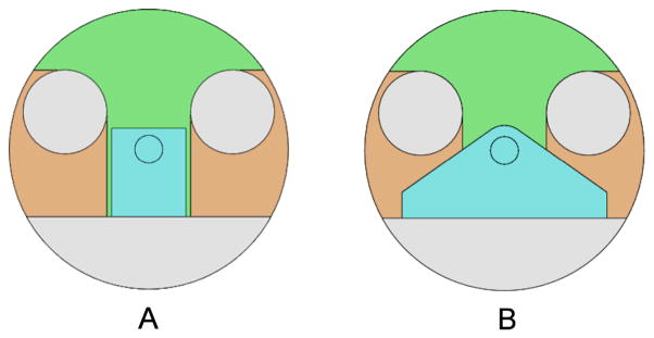
Two-dimensional CAD models of the bore, patient’s legs, and (a) our previous prototype, and (b) current robot. Small circle in robot (blue colored) area represents needle position
MRI compatibility
The effects of the robotic system on the MRI imaging in terms of signal-to-noise-ratio (SNR) was quantified using National Electrical Manufacturers Association (NEMA) standard method (20). Tests were performed on three 3T MRI scanners: Philips Achieva (Philips Medical Systems), GE Excite HD (GE Healthcare), and Siemens Magnetom Verio (Siemens AG). Two widely used T1 and T2 weighted imaging sequences with parameters that are used for usual patient prostate scanning, were used for the MRI compatibility study. Table 2 shows the MRI sequence parameters that used in the study.
Table 2.
MRI scan sequence parameters
| Philips | GE | Siemens | ||||
|---|---|---|---|---|---|---|
| T1w | T2w | T1w | T2w | T1w | T2w | |
| Slice Thickness (mm) | 5 | 5 | 3 | 3 | 3 | 3 |
| FOV (mm) | 240 | 240 | 340 | 340 | 250 | 250 |
| Repetition Time (TR) (ms) | 225 | 3000 | 385 | 3000 | 700 | 300 |
| Echo Time (TE) (ms) | 2.3 | 90 | 5.3 | 105 | 22 | 105 |
| Pixel Bandwidth (Hz/Pixel) | 1060 | 1036 | 122 | 122 | 205 | 122 |
| Flip Angle (deg) | 75 | 90 | 65 | 90 | 150 | 90 |
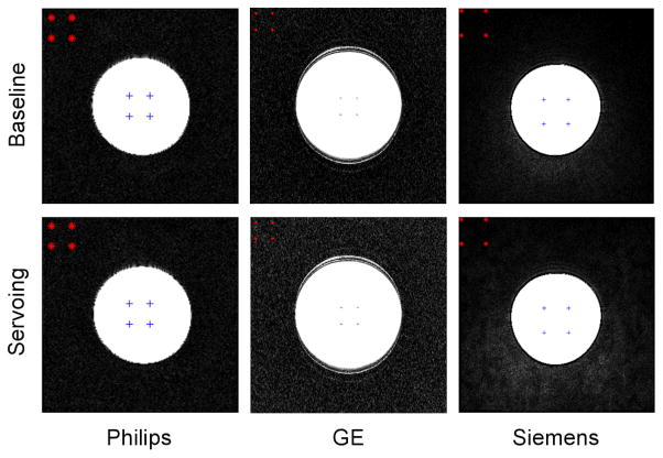
Each set of experiments consisted of the phantom being imaged alone (baseline) and subsequently imaged under following four configurations: 1) Baseline. 2) System in place: Image the phantom after placing the robot. The phantom and robot position approximate prostate and robot position in a clinical procedure. The controller is located in the scanner room but is powered off. 3) System powered: Image the phantom after powering the controller on but piezo servo valves are not enabled. 4) Servoing: piezo servo valves are servoing. Often, MRI scanner room is equipped with electromagnetic noise filtered patch panel. This allows an AC-DC power converter for the controller to be located outside the scanner room to minimize electromagnetic noise. However, at Siemens scanner room, patch panel was unavailable so that the converter was located inside the scanner room. Ten (five for a few scan sequences) axial image slices close to the center of the spherical phantom were obtained for each configuration for each imaging sequence. To normalize the values among the three scanners, a percentile value (when baseline SNR value is 100%) was calculated. Fig. 5 shows a MRI compatibility study (SNR test) setup.
Fig. 5.
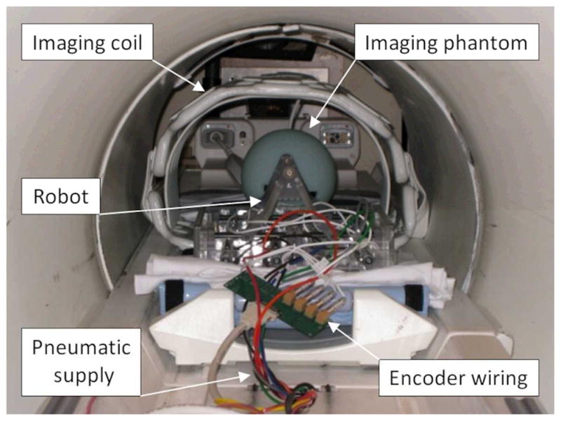
A photo of MRI compatibility study (SNR test) setup using a phantom in GE Excite HD scanner (GE Healthcare)
Results
Effective Workspace
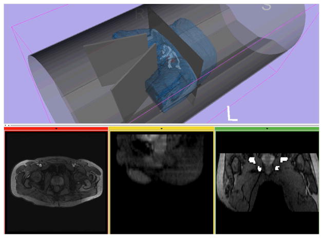
Fig. 6 shows a representative 3D model of the patent, pelvic bone, prostate and the bore of the scanner, created from human subject images. The models acquired from the three volunteers indicated the patient’s occupational volume ratio (VS/VB) of 0.24 and subject’s projection-over-bore (VP/VB) of 0.33 over entire available bore space. Table 3 shows the combined evaluation results of the robots, the overlapped volume over entire bore i.e., VP∩R/VB and VP∩S/VB, and the volumes of effective workspace (VW). The current robot design resulted in the effective workspace (VW) of 0.32, which is greater than that of the early prototype despite that the current robot is approximately 50% larger than the early prototype in sectional space. Also, the dead space utilization by robot design was only found in the current robot. The utilized volume over bore space (VP∩R/VB) resulted in 0.16, whereas the early prototype has none. The volunteer study also indicated that the size of the prostate was 35.7 ± 1.7 mm in anterior-posterior direction and 47.3 ± 4.1 mm in right-left direction, and the vertical position of the prostate from the surface of the patient table was higher than 93.5 ± 7.1 mm and lower than 130.6 ± 1.0 mm, which can be sufficiently covered by the range of motion of the robot.
Fig. 6.
A 3D model of a subject generated from MR images is visualized with models of the bore and the leg splitting tool in medical image processing and visualization software based on 3D Slicer (www.slicer.org)
Table 3.
The mean estimated volumetric parameters for the current and early prototype MRI-compatible robots normalized by the volume of the bore (excluding the space under the patient table)
| Space | Form | Early Prototype | Current Robot |
|---|---|---|---|
| Subject’s space over bore | VS/VB | 0.24 | 0.24 |
| Projection space over bore | VP/VB | 0.33 | 0.33 |
| Robot space over bore | VR/VB | 0.15 | 0.27 |
| Robot overlapped space | VP∩R/VB | 0 | 0.16 |
| Subject overlapped space | VP∩S/VB | 0 | 0 |
| Effective workspace | VW | 0.28 | 0.32 |
MRI Compatibility
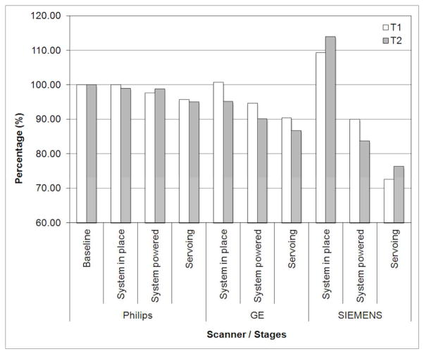
Fig. 7 shows the plot of SNR results. Overall, all three scanner SNR results show a typical reduction pattern i.e. gradual decrease from baseline to servoing configuration, which can be found in similar study (13). Philips and GE scanner SNR tests resulted in similar values: less than 5%, 10% and 15% reduction at physical presence, providing controller power, and servoing configuration, respectively. The Siemens scanner SNR result, however, shows greater SNR value decrease, approximately from 110% (it is not unusual to find a SNR value greater than baseline value) to 75%. For all scanners and configurations, two imaging sequence T1 and T2 resulted in very similar SNR values.
Fig. 7.
MRI compatibility study (SNR test) results in percentile. Philips and GE scanner SNR tests resulted in similar values: less than 5%, 10% and 15% reduction at physical presence, providing controller power, and servoing configuration, respectively. The Siemens scanner SNR result shows greater SNR value decrease from 110% to 75%
Discussion
As preliminary evaluation of our prostate intervention robot with workspace-oriented design, we conducted a workspace analysis using a new evaluation method that we developed for in-bore operated robots for transperineal prostate interventions, and an MRI compatibility study. One of the key requirements that has been discussed from existing in-bore operated MRI-compatible robot developments is the robot design optimization to enhance clinical adaptability. We observed that the unused ‘under-legs’ space can be utilized for robot design to optimize the use of the confined space and allow the maximum clinical access.
The workspace analysis method allows us to quantify the in-bore workspace utilization of existing MRI-compatible robots. The method is straightforward yet efficient to distinguish “effective workspace”, which can be utilized by the clinician, from “dead space” within the free space of the bore. This will allow developers to evaluate and optimize their mechanical designs to maximize accessibility to the patient in the bore, thus improving utility and safety of their robots before fabrication. The method provides useful parameters to evaluate workspace in the bore.
The workspace optimization could provide sufficient clinical access space so that patients remain at imaging position i.e. not moving patient out for needle insertion. This can increase imaging position consistency and reduce procedural time. Procedures in wide-bore (70 cm bore diameter) scanners, in particular, can benefit greatly from the workspace optimization, since the wide-bore yields larger free space to be utilized for clinician’s access while the patient remains at imaging position. The clinical significance of our approach is the improved access to the patient in the MRI scanner. The MRI-guided prostate interventions in a closed-bore MRI scanner usually require frequent transfer of the patient between inside and outside of the bore due to the limited access to the patient, which may increase a risk of disconnection of cables and tubes for vital monitoring and transfusions.
In-bore operated robots found in literature have both serial and parallel kinematic structure. Serial structure can be compact but produce greater error as joint errors accumulate. In contrary, parallel structure can occupy larger space but provide greater rigidity since it distributes reaction and/or external forces to more than one joint. In our pneumatically actuated robot developments, in particular, a low friction air-cylinder driven joint that has no transmission reduction e.g. gear seems unsuitable for a serially linked robot, since it requires larger force (higher air pressure) to drive joints and to withstand overall robot structure in general.
Similar to our current design approach, Su reported a parallel structure robotic system that resembles the kinematic structure of our robot (21). The robot prototype also utilized the “under-the-leg” space, allowing more space for mechanical structure in “dead space” and leaving larger free space above and around needle for clinical access.
Sterilization also affects the workspace design since it may require additional space to provide and secure sterile area. Our current robot design, we proposed partial plasma sterilization of the robot’s top parts, which are detachable from the rest of the robot. This partial sterilization and draping the rest, however, seems rather complex in practice. Considering the difficulties of full sterilization of mechanical components and the complex partial sterilization, disposable parts can be used, which is common in clinical practice. Nonetheless, sterilization should be taken into account in the design stage.
In the new workspace evaluation method, we calculated the effective workspace by normalizing the measured values by entire bore space, resulting in small numerical differences among different robot designs. For more distinctive comparison, direct robot workspace comparison or normalization by useable bore space i.e. except subject space can be used for the calculation. Also, due to the lack of quantified clinical access space information, our study is limited to the utilization of unusable space rather regardless of clinical access space. In future study, however, it will be necessary to investigate the clinical access space with numerical quantification so that full workspace analysis of in-bore operated robotic intervention can be performed.
The advantage of our method is that the estimation of the workspace parameters requires only limited dimensional information. This was made possible by the assumption that the dead space is defined as the space covered by the projections of the robotic device and the patient legs parallel to the static field. Although this assumption is not always true for other magnet configurations, e.g. open-bore MRI scanners, the same concept could be used for any other magnet configurations by using additional dimensional information.
The MRI compatibility study resulted in less than 15% signal-to-noise ratio (SNR) reduction, suggesting that the robotic system causes insignificant image quality degrading with the designated system setup i.e. powered through patch panel. In other words, an adequate degree of MRI compatibility was observed. The MRI compatibility study of our early prototype, which used the identical controller and wiring, resulted in no more than 5% loss in SNR in Philips 3T scanner (13). Comparatively, in (22), authors reported an MRI compatibility study of an ultrasonic motor actuated transrectal prostate robot in 3T MRI. The results suggested no measurable reduction of SNR in the motor-off configuration and a 40% to 60% reduction in SNR with the motors on.
In conclusion, we conducted a workspace design analysis using a new evaluation method that we developed for in-bore operated robots and an MRI compatibility study for the evaluation of our current needle guide robot for 3T MRI-guided transperineal prostate intervention. The new workspace evaluation method quantifies the workspace utilization of the in-bore operated robots for MRI-guided transperineal prostate interventions, providing a useful tool for evaluation and new robot design. The robot creates insignificant electromagnetic noise during typical prostate imaging sequences.
Fig. 8.
Representative T1 phantom images obtained from the MRI compatibility study. Upper row shows the baseline images and the lower row shows the images when robot is servoing
Acknowledgments
This project was supported by the National Cancer Institute, the National Center for Research Resources and the National Institute of Biomedical Imaging and Bioengineering of the National Institutes of Health through Grant Numbers 1R01CA111288, R01CA124377, 5R01CA138586, 5P01CA067165, P41EB015898 and P41RR019703; New Energy and Industrial Technology Development Organization Grant; Center for Integration of Medicine and Innovative Technology Grant 11-325.
References
- 1.Wefer AE, Hricak H, Vigneron DB, Coakley FV, Lu Y, Wefer J, Mueller-Lisse U, Carroll PR, Kurhanewicz J. Sextant localization of prostate cancer: comparison of sextant biopsy, magnetic resonance imaging and magnetic resonance spectroscopic imaging with step section histology. J Urol. 2000;164(2):400–404. [PubMed] [Google Scholar]
- 2.Yu KK, Hricak H. Imaging prostate cancer. Radiol Clin North Am. 2000;38(1):59–85. viii. doi: 10.1016/s0033-8389(05)70150-0. [DOI] [PubMed] [Google Scholar]
- 3.Pondman KM, Futterer JJ, ten Haken B, Schultze Kool LJ, Witjes JA, Hambrock T, Macura KJ, Barentsz JO. MR-guided biopsy of the prostate: an overview of techniques and a systematic review. Eur Urol. 2008;54(3):517–527. doi: 10.1016/j.eururo.2008.06.001. [DOI] [PubMed] [Google Scholar]
- 4.Futterer JJ, Barentsz J, Heijmijnk ST. Imaging modalities for prostate cancer. Expert Rev Anticancer Ther. 2009;9(7):923–937. doi: 10.1586/era.09.63. [DOI] [PubMed] [Google Scholar]
- 5.D’Amico AV, Cormack R, Tempany CM, Kumar S, Topulos G, Kooy HM, Coleman CN. Real-time magnetic resonance image-guided interstitial brachytherapy in the treatment of select patients with clinically localized prostate cancer. Int J Radiat Oncol Biol Phys. 1998;42(3):507–515. doi: 10.1016/s0360-3016(98)00271-5. [DOI] [PubMed] [Google Scholar]
- 6.D’Amico AV, Tempany CM, Cormack R, Hata N, Jinzaki M, Tuncali K, Weinstein M, Richie JP. Transperineal magnetic resonance image guided prostate biopsy. J Urol. 2000;164(2):385–387. [PubMed] [Google Scholar]
- 7.Engelhard K, Hollenbach HP, Kiefer B, Winkel A, Goeb K, Engehausen D. Prostate biopsy in the supine position in a standard 1.5-T scanner under real time MR-imaging control using a MR-compatible endorectal biopsy device. Eur Radiol. 2006;16(6):1237–1243. doi: 10.1007/s00330-005-0100-6. [DOI] [PubMed] [Google Scholar]
- 8.Hambrock T, Futterer JJ, Huisman HJ, Hulsbergen-vandeKaa C, van Basten JP, van Oort I, Witjes JA, Barentsz JO. Thirty-two-channel coil 3T magnetic resonance-guided biopsies of prostate tumor suspicious regions identified on multimodality 3T magnetic resonance imaging: technique and feasibility. Invest Radiol. 2008;43(10):686–694. doi: 10.1097/RLI.0b013e31817d0506. [DOI] [PubMed] [Google Scholar]
- 9.Menard C, Susil RC, Choyke P, Gustafson GS, Kammerer W, Ning H, Miller RW, Ullman KL, Sears Crouse N, Smith S, Lessard E, Pouliot J, Wright V, McVeigh E, Coleman CN, Camphausen K. MRI-guided HDR prostate brachytherapy in standard 1.5T scanner. Int J Radiat Oncol Biol Phys. 2004;59(5):1414–1423. doi: 10.1016/j.ijrobp.2004.01.016. [DOI] [PMC free article] [PubMed] [Google Scholar]
- 10.Susil RC, Camphausen K, Choyke P, McVeigh ER, Gustafson GS, Ning H, Miller RW, Atalar E, Coleman CN, Menard C. System for prostate brachytherapy and biopsy in a standard 1.5 T MRI scanner. Magn Reson Med. 2004;52(3):683–687. doi: 10.1002/mrm.20138. [DOI] [PMC free article] [PubMed] [Google Scholar]
- 11.Susil RC, Menard C, Krieger A, Coleman JA, Camphausen K, Choyke P, Fichtinger G, Whitcomb LL, Coleman CN, Atalar E. Transrectal prostate biopsy and fiducial marker placement in a standard 1.5T magnetic resonance imaging scanner. J Urol. 2006;175(1):113–120. doi: 10.1016/S0022-5347(05)00065-0. [DOI] [PMC free article] [PubMed] [Google Scholar]
- 12.Stoianovici D, Song D, Petrisor D, Ursu D, Mazilu D, Muntener M, Schar M, Patriciu A. “MRI Stealth” robot for prostate interventions. Minim Invasive Ther Allied Technol. 2007;16(4):241–248. doi: 10.1080/13645700701520735. [DOI] [PMC free article] [PubMed] [Google Scholar]
- 13.Fischer GS, Iordachita I, Csoma C, Tokuda J, Dimaio SP, Tempany CM, Hata N, Fichtinger G. MRI-Compatible Pneumatic Robot for Transperineal Prostate Needle Placement. IEEE ASME Trans Mechatron. 2008;13(3):295–305. doi: 10.1109/TMECH.2008.924044. [DOI] [PMC free article] [PubMed] [Google Scholar]
- 14.Goldenberg AA, Trachtenberg J, Kucharczyk W, Haider YYM, Ma L, Weersink R, Raoufi C. Robotic System for Closed-Bore MRI-Guided Prostatic Interventions. IEEE/ASME Transactions on Mechatronics. 2008;13(3):374–379. [Google Scholar]
- 15.van den Bosch MR, Moman MR, van Vulpen M, Battermann JJ, Duiveman E, van Schelven LJ, de Leeuw H, Lagendijk JJ, Moerland MA. MRI-guided robotic system for transperineal prostate interventions: proof of principle. Phys Med Biol. 2010;55(5):N133–140. doi: 10.1088/0031-9155/55/5/N02. [DOI] [PubMed] [Google Scholar]
- 16.Yakar D, Schouten MG, Bosboom DG, Barentsz JO, Scheenen TW, Futterer JJ. Feasibility of a pneumatically actuated MR-compatible robot for transrectal prostate biopsy guidance. Radiology. 2011;260(1):241–247. doi: 10.1148/radiol.11101106. [DOI] [PubMed] [Google Scholar]
- 17.Su H, Zervas M, Cole G, Furlong C, Fischer G. Real-time MRI-Guided Needle Placement Robot with Integrated Fiber Optic Force Sensing. IEEE Int Conf Robot Autom. 2011:1583–1588. [Google Scholar]
- 18.Song SE, Cho NB, Fischer G, Hata N, Tempany C, Fichtinger G, Iordachita I. Development of a Pneumatic Robot for MRI-guided Transperineal Prostate Biopsy and Brachytherapy: New Approaches. IEEE Int Conf Robot Autom. 2010;2010:2580–2585. doi: 10.1109/ROBOT.2010.5509710. [DOI] [PMC free article] [PubMed] [Google Scholar]
- 19.Song SE, Cho N, Tokuda J, Hata N, Tempany C, Fichtinger G, Iordachita I. Preliminary Evaluation of a MRI-compatible Modular Robotic System for MRI-guided Prostate Interventions. Proc IEEE RAS EMBS Int Conf Biomed Robot Biomechatron. 2010;2010:796–801. doi: 10.1109/BIOROB.2010.5626987. [DOI] [PMC free article] [PubMed] [Google Scholar]
- 20.NEMA. MS 1-2008 Determination of Signal-to-Noise Ratio (SNR) in Diagnostic Magnetic Resonance Imaging. The National Electrical Manufacturers Association (NEMA); 2008. http://www.nema.org/stds/ms1.cfm. [Google Scholar]
- 21.Su H, Iordachita I, Yan X, Cole G, Fischer GS. Reconfigurable MRI-Guided Robotic Surgical Manipulator: Prostate Brachytherapy and Neurosurgery Applications. Proceedings of the 33rd Annual International Conference of the IEEE Engineering in Medicine and Biology Society (EMBC); 2011. [DOI] [PubMed] [Google Scholar]
- 22.Krieger A, Song S-E, Cho NB, Iordachita I, Guion P, Fichtinger G, Whitcomb LL. Development and Evaluation of an Actuated MRI-Compatible Robotic System for MRI-Guided Prostate Intervention. IEEE/ASME Transactions on Mechatronics. 2011:16. doi: 10.1109/TMECH.2011.2163523. [DOI] [PMC free article] [PubMed] [Google Scholar]


