Abstract
Objective
Electrical stimulation of the pudendal nerve (PN) is being developed as a means to restore bladder function in persons with spinal cord injury. A single nerve cuff electrode placed on the proximal PN trunk may enable selective stimulation of distinct fascicles to maintain continence or evoke micturition. The objective of this study was to design a nerve cuff that enabled selective stimulation of the PN.
Approach
We evaluated the performance of both flat interface nerve electrode (FINE) cuff and round cuff designs, with a range of FINE cuff heights and number of contacts, as well as multiple contact orientations. This analysis was performed using a computational model, in which the nerve and fascicle cross-sectional positions from five human PN trunks were systematically reshaped within the nerve cuff. These cross-sections were used to create finite element models, with electric potentials calculated and applied to a cable model of a myelinated axon to evaluate stimulation selectivity for different PN targets. Subsequently, the model was coupled to a genetic algorithm (GA) to identify solutions that used multiple contact activation to maximize selectivity and minimize total stimulation voltage.
Main results
Simulations did not identify any significant differences in selectivity between FINE and round cuffs, although the latter required smaller stimulation voltages for target activation due to preserved localization of targeted fascicle groups. Further, it was found that a 10 contact nerve cuff generated sufficient selectivity for all PN targets, with the degree of selectivity dependent on the relative position of the target within the nerve. The GA identified solutions that increased fitness by 0.7–45.5% over single contact activation by decreasing stimulation of non-targeted fascicles.
Significance
This study suggests that using an optimal nerve cuff design and multiple contact activation could enable selective stimulation of the human PN trunk for restoration of bladder function.
1. Introduction
Spinal cord injury (SCI) can result in neurogenic bladder dysfunction, including urinary incontinence (detrusor overactivity) and inefficient voiding of the bladder (detrusor-sphincter dyssynergia), and lead to recurring urinary tract infections, kidney damage, and a reduction in quality of life.[1, 2] Electrical stimulation of sensory branches of the pudendal nerve (PN) is being developed as a means to restore urinary function in persons with SCI.[3] The PN originates in the sacral spinal cord and innervates the external urethral sphincter, urethra, external anal sphincter, and genitalia, and contains both motor and sensory fibres.[4] Stimulation of the dorsal genital nerve (DGN) and inferior rectal nerve (IRN) branches of the PN at low frequencies inhibits hyper-reflexive bladder contractions in subjects with SCI [5–10]. Conversely, activation of PN afferents at higher frequencies in spinalized cats and SCI subjects evokes bladder contractions.[10–13] The objective of the present study was to analyze and design multiple contact nerve cuff electrodes that enable selective stimulation of the PN and thereby enable control of both continence and micturition in persons with SCI.
Accessing individual distal branches of the PN for electrode implantation requires invasive surgery, which can result in morbidity [4], and multiple electrodes must be implanted to stimulate different PN branches. Alternatively, multiple contact nerve cuff electrodes enable selective stimulation of targeted fascicles within a nerve trunk with just a single implant [14, 15], and selective stimulation of the proximal compound PN trunk is a promising approach for control of bladder function. The compound PN trunk is surgically accessible, has a sufficient length and diameter for nerve cuff placement, and contains representations of distal branches as discrete fascicles or groups of fascicles with relatively stable locations along the length of the trunk.[4]
The stimulation selectivity of nerve cuff electrodes is dependent on the electrode shape, with flat interface nerve electrode (FINE) cuffs potentially providing improved selectivity over nerve cuffs with round cross-sections.[16–18] The FINE cuff reshapes the oblong nerve into a flat configuration by applying small amounts of pressure, thereby moving the fascicles into a planar alignment and reducing the distance between targeted fascicles and the closest electrode contacts.[18] The acute pressure applied by the nerve cuff typically decreases as the nerve reshapes. Nevertheless, using a narrow FINE cuff can reduce blood flow and result in compressive neuropathy.[19]
We used a computational model to evaluate nerve cuff designs in selective stimulation of fascicles within the PN trunk constituting the DGN, IRN, and perineal nerve (PerN) branches. The design parameters included the: (i) cuff shape, with both FINE and round cuffs, (ii) cuff size, (iii) total number of contacts on the cuff, and (iv) contact orientation. Nerve cuff designs were evaluated using models of five PN cross-sections obtained from human cadavers.[4] A quantitative reshaping algorithm was used to reposition fascicles within the nerve cuffs, and axonal activation was calculated with finite element method (FEM) models coupled to a cable model of a mammalian, myelinated axon. We first analyzed different nerve cuff designs on the basis of stimulation selectivity using single contact activation. Subsequently, multiple contacts were activated simultaneously for improved selectivity [14, 15, 20], and optimal solutions were identified using a genetic algorithm [21]. The results of this study provide nerve cuff designs and stimulation methods for maximizing stimulation selectivity of targets in the proximal PN trunk and thereby enabling restoration of bladder function.
2. Methods
We analyzed the stimulation selectivity of nerve cuff electrode designs using a three stage computational model. The first stage of the model was a reshaping algorithm used to calculate the positions of the nerve and fascicles within the cuff. The second stage was FEM models that calculated the potentials generated by the nerve cuffs in a three-dimensional representation of the nerve and surrounding tissue. In the third stage, the potentials were coupled to a cable model of a mammalian, myelinated axon to calculate stimulation thresholds for axonal activation in the PN trunk.
2.1 Nerve Cuff Design
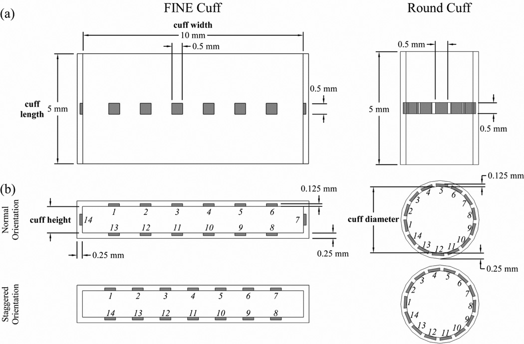
Stimulation selectivity was calculated for nerve cuff designs with different shapes, sizes, and numbers of contacts (figure 1). We tested FINE cuffs with heights between 1.0 and 1.4 mm, in 0.1 mm increments. The minimum FINE cuff height was chosen because it was larger than the largest PN fascicle, thereby reducing the risk of compressive neuropathy. The maximum FINE cuff height was chosen because it mildly reshaped the largest PN trunk. We also tested round (cylindrical) cuffs, with diameters dependent on the cross-sectional area (CSA) of the PN trunk tested. Nerve cuffs had fixed lengths of 5 mm, thicknesses of 0.25 mm, and FINE widths of 10 mm. For each cuff shape, a range of contact numbers between 2 and 14 were tested, in increments of 2, with 3 contacts also tested. The contacts were equally spaced and located symmetrically around the nerve cuff, centered halfway along the length of the cuff. The contacts were 0.5 mm × 0.5 mm squares, 0.125 mm thick, and were embedded into the cuff such that the inner surface of the contact was aligned with the inner surface of the insulating cuff. In the round cuff, the contacts were curved to match the radius of curvature of the inner surface of the cuff.
Figure 1.
Geometries of the flat interface nerve electrode (FINE) cuff and round cuff electrodes used for selective stimulation of the pudendal nerve (PN) shown from the (a) top view and (b) transverse view. The insulating cuff is shown in white, and the contacts are shaded. The design parameters that were varied included: the cuff shape (FINE or round), FINE cuff height, number of contacts, and contact orientation. Contacts were numbered in a clockwise manner, and are shown in both the normal and staggered orientations.
The selectivity of a given nerve cuff design was also analyzed across contact orientations (figure 1). There were two orientations on the FINE cuff, either with or without a single contact on each side along the height dimension of the cuff, designated as normal and staggered orientations, respectively. The exception was a FINE cuff with 3 contacts, in which there were four orientations consisting of all potential combinations of contact locations with a maximum of 1 contact per side. For the round cuff, there were two contact orientations that differed by circumferential rotation of all contacts by half of the contact spacing. For the normal orientation, the first contact was formed by placing one edge at 180° on the Cartesian plane and revolving in a counter-clockwise direction.
2.2 Reshaping Algorithm
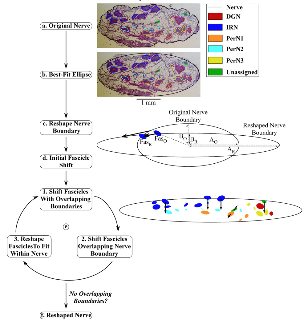
The first stage of the computational model was a reshaping algorithm that identified the nerve and fascicle coordinates and performed a series of calculations to reshape the nerve boundary and fascicle locations within the nerve cuff (figure 2). The nerve and fascicle boundaries from color images of stained, transverse cross-sections of five proximal PN trunks from human cadavers were manually traced in Adobe Photoshop.[4] The high fascicle density of the PN trunk in the published image of nerve 3,L made some fascicle boundaries indistinguishable; therefore, another stained section of the proximal PN trunk from the same cadaver with slightly reduced fascicle density was substituted for analysis. Pixel coordinates of the boundaries were imported into MATLAB (MathWorks) using the Image Processing Toolbox and converted from pixels to millimeters (figure 2(a)). Best-fit ellipses were then calculated for the boundaries of the nerve and each fascicle (figure 2(b)), and the ellipse representations were used in subsequent analysis to improve FEM meshing performance in the second stage of the model. A 50 µm separation was maintained between all nerve and fascicle boundaries to ensure reliable FEM meshing.
Figure 2.
Block diagram of the algorithm used for systematic nerve reshaping. (a) The original nerve and fascicle boundaries from nerve 7,L. (b) The best-fit ellipses of the boundaries were computed. (c) The nerve boundary was reshaped to fit within a FINE cuff of 1.2 mm height. The length of the major (A) and minor (B) ellipse axes were adjusted such that the area of the nerve was preserved in the original (O) and reshaped (R) nerve cross-sections: AO×BO = AR×BR. (d) An initial shift was made for each fascicle in the same direction as and half the distance of the shift of a nearby nerve boundary point, which was identified according to angular alignment of the center of the fascicle in Cartesian coordinates with the nerve center at the origin. The position of one fascicle is shown in the original (FasO) and reshaped (FasR) cross-sections. (e) The fascicles were moved and/or reshaped in a repeated three-step process: 1) shifting of overlapping fascicles away from one another each by half of the movement increment, 2) shifting of fascicles overlapping the nerve boundary inward by the movement increment, and 3) reshaping of fascicles to fit within the nerve boundary. An example of the magnitude and direction of fascicle shifting during the first loop is shown, with the arrow length equal to ten times the mean movement increment for easier visualization. (f) The loop proceeded until there were no longer any overlapping boundaries, at which point the reshaped nerve cross-section was identified.
The nerve boundary was reshaped by assuming complete deformation to the nerve cuff geometry, as is observed following chronic implantation of both round and FINE cuffs (figure 2(c)) [19, 22], subject to the constraint that the original CSA of the nerve was preserved. The FINE cuff was centered on the nerve, the nerve minor axis reduced to the cuff height minus twice the 100 µm spacing between the inner surface of the cuff and the nerve boundary, and the major axis increased to maintain the original CSA. The round cuff was centered on the nerve, which was reshaped into a circular boundary with its original CSA. The nerve cuff diameter was equal to the sum of the reshaped nerve diameter and twice the 100 µm between the inner cuff surface and the nerve boundary. The 100 µm spacing enabled representation of the encapsulation tissue between the nerve and cuff.
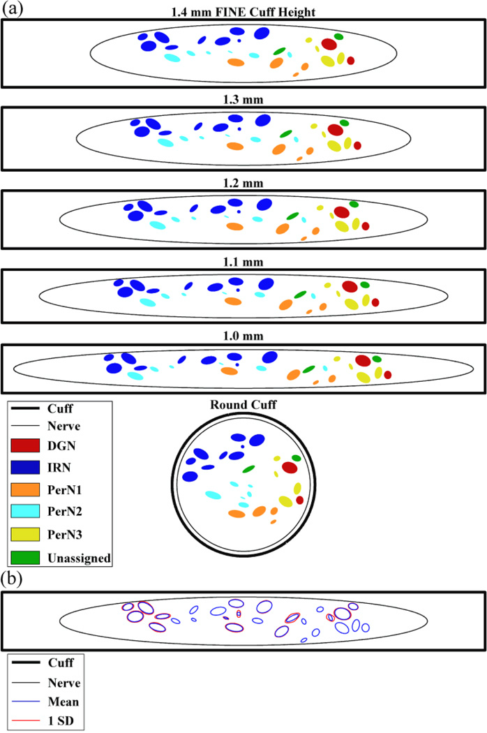
The reshaping algorithm shifted the fascicles within the reshaped nerve boundary. An initial shift was made by moving each fascicle in the same direction as and half the distance of the movement of a nearby nerve boundary point that occurred during the nerve boundary reshaping (figure 2(d)). This shift was intended to account for the mechanical resistance to fascicle movement within the epineurium. Subsequently, the fascicles were shifted in a series of steps until all fascicles were within the reshaped nerve boundary and no fascicles were overlapping (figure 2(e)). Within each step, the algorithm first shifted any fascicles with overlapping boundaries away from one another, each by half of the movement increment defined as 50 ± 16.7 µm (mean ± SD). Second, any fascicles with boundaries overlapping with or outside of the nerve boundary were shifted inward by the movement increment in a direction away from the nerve boundary. Third, if any fascicle was larger than the reshaped nerve, the fascicle was reshaped to fit within the nerve boundary while maintaining the original CSA of the fascicle. In subsequent steps, the algorithm attempted to restore the reshaped fascicle boundary towards its original shape, if possible, based on its position within the nerve. As was the case for the original cross-section, a 50 µm separation was maintained between all nerve and fascicle boundaries. The reshaping algorithm proceeded through several steps until there were no longer any overlapping boundaries (figures 2(f), 3(a)). The variation in movement increment values implemented during fascicle movement represented intra-patient deviation in fascicle position following nerve cuff implantation (figure 3(b)).
Figure 3.
Cross-sectional positions of the nerve and fascicle boundaries calculated by the reshaping algorithm for nerve 7,L. (a) The position of the nerve and fascicles within FINE cuffs of various heights or within the round cuff. There was 100 µm between the nerve boundary and inner cuff surface along the cuff height dimension. (b) The mean fascicle boundary locations, and one standard deviation (SD) from the mean, resulting from three reshaping trials with a FINE cuff of 1.2 mm height. This variability was introduced within the reshaping algorithm by adding noise to the movement increment.
2.3 Finite Element Method Models
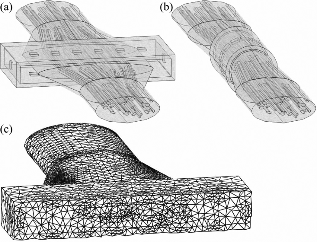
The second stage was FEM models used to calculate the potentials generated by the nerve cuff in the nerve and surrounding tissue. A three-dimensional representation of each PN trunk was constructed in Comsol Script 1.2 (COMSOL) by extruding the original and reshaped cross-sections each to 5 mm in length, and connecting these segments by linearly lofted segments having the same length (figure 4(a),(b)). The resulting length of the entire modeled nerve was 25 mm. If any fascicles overlapped in the lofted segments, they were shifted away from each other at the point of intersection by an increment of 25 µm each until no longer intersecting. Both the nerve and cuff were surrounded by a cubic volume conductor with 25 mm length, centered at the middle of the nerve cuff, representing surrounding tissue. This modeled tissue volume was sufficiently large because increasing the length of each side of the cube by 50% changed the potentials within the nerve cuff by <7.7% (mean ± SD = 0.9 ± 0.8%).
Figure 4.
Three-dimensional geometry of nerve 7,L in the finite element method (FEM) models, reshaped by (a) a FINE cuff with 1.2 mm height, and (b) a round cuff. Both nerve cuffs are shown with 14 contacts in the normal orientation. Note that the cubic volume conductor is not shown. (c) Variable discretization mesh of the geometry in (a) with a transverse cut through the center of the nerve cuff for visualization.
The electrical properties of the geometrical domains were based on published values (table 1).[23–27] All domains were modeled with conductivity values that were isotropic and homogenous, except the endoneurium, which was anisotropic in the transverse and longitudinal directions. The perineurium was modeled as a distributed resistance boundary with a thickness equal to 3% of the fascicle diameter.[28] The boundary of the active stimulating contact(s) was set to a constant voltage and the outer boundary of the cubic representation of the tissue was grounded. All remaining geometrical boundaries were set to a continuity of normal current density condition.
Table 1.
Conductivity of FEM model domains.
| Component | Conductivity (S/m) |
|---|---|
| Perineurium | 8.3×10⁻⁴ |
| Epineurium | 1.0 |
| Endoneurium (Transverse) | 0.1 |
| Endoneurium (Longitudinal) | 1.0 |
| Tissue | 6.6×10⁻² |
| Cuff (Silicon Rubber) | 1×10⁻¹⁷ |
| Contact (Platinum) | 9.4×10⁶ |
The FEM mesh used a variable discretization interval, with regions closer to the electrode discretized at smaller intervals than distant regions (figure 4(c)). The mesh used tetrahedral elements with a maximum size of 60% of the radius of curvature along a geometrical border, and a maximum growth rate between adjacent elements of 50%. The resulting mesh had over 500,000 elements for FINE cuff models and over 200,000 elements for round cuff models, and this was a sufficient mesh density as doubling the number of elements changed the potentials within the cuff by <10.2% (mean ± SD = 3.6 ± 2.1%). Although uncommon, Comsol Script was sometimes unable to mesh the model for particular combinations of PN trunk geometries and nerve cuff designs. In those cases, the model was modified either by shifting all contacts a small distance (less than 2% of the contact spacing) in a clockwise or counter-clockwise manner within the transverse plane, or by increasing the cuff height by less than 2% of the desired cuff height.
The potentials generated by the active stimulating contact(s) were solved at the FEM mesh nodes using the conjugate gradients solver with a geometric multigrid preconditioner. It was assumed that the field was imposed instantaneously (i.e., that there was a small reactive component relative to the real component of the tissue conductivity).[25, 29]
2.4 Cable Model of a Myelinated Nerve Axon
The third stage was a multi-compartment cable model of a myelinated axon implemented using the NEURON software package.[30] Axonal dynamics were described using the Sweeney model of a myelinated, mammalian nerve fibre (table 2).[31–33] This model assumes perfectly insulated internodal segments and includes fast sodium and leakage channel currents in parallel with a membrane capacitance at the nodes of Ranvier.
Table 2.
Axon electrical and geometrical properties.
| Component | Symbol | Value | |
|---|---|---|---|
| Fast Sodium Nernst Potential | ENa | 35.64 mV | |
| Leakage Reversal Potential | EL | −80.01 mV | |
| Maximum Fast Sodium Conductance |
|
1445 mS/cm2 | |
| Leakage Conductance | gL | 128 mS/cm2 | |
| Resting Potential | ER | −80 mV | |
| Membrane Capacitance | cm | 2.5 µF/cm2 | |
| Axoplasmic Resistivity | ρA | 54.7 Ω-cm | |
| Nodal Gap Width | L | 1.5 µm | |
| Axon Diameter | d | 7.2 µm | |
| Internodal Length | L | 1 mm |
The potentials calculated in the FEM models were applied to the cable model to determine stimulation thresholds for axons in the PN trunk. Each fascicle contained 20 randomly-positioned axons that followed the same course as the fascicle in which they were bounded. The longitudinal distance between the center of the contacts and the nearest node of Ranvier was uniformly distributed across axons. Extracellular potentials (Ve) from the FEM models were interpolated at the nodes of Ranvier of each axon, and the equivalent intracellular current (Iinj) was injected at node i using equation 1, where Ra is the intracellular resistance.[33] If the node was located at the end of an axon, the first difference was instead used in the numerator of equation 1.
| (1) |
The NEURON simulation was run with a time step of 1 µs for a total time of 2 ms. Following a 0.1 ms initialization period, a stimulation pulse of 100 µs duration was delivered and any resulting action potential was detected using a transmembrane potential threshold of −20 mV.
2.5 Selectivity Analysis of Single Contact Activation
The three-stage model was used to analyze the stimulation selectivity for different PN targets with each nerve cuff design using single contact activation. Each contact on the nerve cuff was individually activated using a 1 V boundary condition, and the resulting potentials were solved in the FEM models. Since the bulk conductivity was linear, the potentials generated by different stimulation amplitudes were calculated as scaled versions of the original 1 V solution. Using the scaled FEM solutions and cable model, the threshold was calculated for every PN axon for a cathodic stimulation pulse at each contact (±1 µV tolerance). Next, the recruitment cost (RC) for stimulation of all targeted fascicles was calculated using equation 2, where a targeted fascicle was designated as activated if all 20 representative axons in that fascicle were stimulated. The fascicle selectivity ratio (FASR) was then calculated using equation 3, with values ranging from 0 (all non-targeted axons were stimulated) to 1 (none of the non-targeted axons were stimulated).[18]
| (2) |
| (3) |
The FASR for a target fascicle group (DGN, IRN, PerN1, PerN2, or PerN3) was calculated for all contacts, and the maximum value across contacts was determined. Finally, this maximal FASR value was averaged across the contact orientations of the particular nerve cuff design (fixed cuff shape, cuff size, and number of contacts) to calculate its characteristic FASR.
Population values for characteristic FASRs, stimulation voltages, and the optimal numbers of contacts (ONC) were calculated by averaging the values for each target across the five PNs. Target PerN3 was not present in nerve 3,L, and the values from the other four nerves were averaged. Stimulation voltages were calculated for the active contact that maximized FASR, and then averaged across the contact orientations for the particular nerve cuff design and PN target being tested. The ONC for each nerve cuff design and PN target was defined as the minimum number of contacts needed to achieve at least 90% of the maximum characteristic FASR value possible for that nerve cuff shape and size.
2.6 Optimal Multiple Contact Activation
We quantified improvements in selectivity over single contact activation that resulted from simultaneous activation of multiple contacts. The number of permutations of multiple contact activation is infinite, as each contact can be set to a different voltage. Therefore, an optimization approach using a genetic algorithm (GA) was used to determine the voltages at each contact that maximized selective stimulation of a particular PN target while minimizing the sum of absolute contact voltages. The GA methodology mimics the process of biological evolution, and enables a wide search of the solution space before converging to an optimal solution over the course of multiple generations.[34] This analysis was conducted for nerve 7,L using a round cuff and a FINE cuff with 1.0 mm height, each with 14 contacts positioned in the normal orientation.
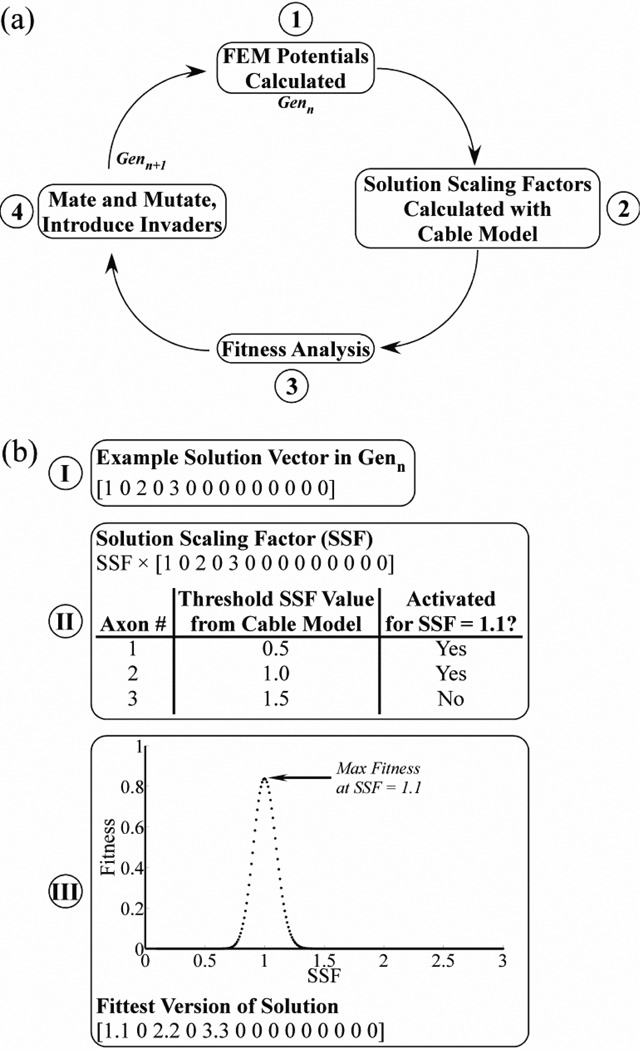
The GA-based optimization employed a four-step iterative process (figure 5(a)). Each generation included 20 solutions, analogous to individual organisms, with each having a set of 14 genes corresponding to the voltages at each of the 14 contacts. The first generation was randomly initialized with genes of −1 V (25% probability), 0 V (50%), or 1 V (25%), where positive values correspond to anodic stimulation, negative values to cathodic stimulation, and 0 V to a continuity (off) condition. The first step of the GA used the FEM models to calculate the potentials generated by each solution. Second, the potentials for a given solution were applied to the cable model to calculate the threshold solution scaling factor (SSF) required for stimulation of each PN axon individually, with all voltages in a solution multiplied by the SSF (figure 5(b)). Third, using the thresholds for each axon, the fitness of each solution was calculated based on the stimulation selectivity for a PN target and the total voltage (equation 4) for SSFs from 0.1 to 3.0, in 0.01 increments.
| (4) |
| (5) |
Selectivity is the difference between the recruitment benefit (RB) and recruitment cost (RC) of target stimulation, defined in equations 5 and 3, respectively. The voltage term reduced the fitness score in an exponentially scaled manner that plateaued at higher voltages, and was calculated using the sum of absolute voltages across contacts (Vtotal). The weighting constant wv was fixed at 0.1 to constrain the voltage term to a range of 0 to 0.1. The constant α = 0.214, such that this term reached 95% of its maximum value when Vtotal was 14 V (i.e., each contact set to 1 V). For each solution, we found the SSF that maximized fitness and multiplied all voltages in the solution by that SSF value (figure 5(b)).
Figure 5.
Optimizing multiple contact selective stimulation of the PN. (a) Block diagram of the four-step iterative process used in the genetic algorithm (GA) to optimize stimulation selectivity. (b) The use of the solution scaling factor (SSF) in the GA is illustrated with an example. Step I: A solution in Genn was represented by a vector of voltages at each of the 14 contacts. In the case shown, contact 1 was set to 1 V, contact 3 was set to 2 V, contact 5 was set to 3 V, and all other contacts were off. Step II: The threshold SSF value required for stimulation of each PN axon was found individually using the cable model, where all contact voltages were multiplied by the SFF. Step III: The fitness of the solution was evaluated over a range of SSF values to identify the value that maximized fitness, in this case shown as a value of 1.1. All voltages in the solution were multiplied by this optimal SSF value to calculate the fittest solution.
The fourth step of the GA consisted of mating and mutation of solutions in the current generation (Genn) and the introduction of invader solutions, which produced the subsequent generation (Genn+1). The twenty solutions of Genn+1 included the two fittest solutions from Genn, sixteen offspring generated by mating solutions from Genn, and two invaders. To generate the offspring, two parents were randomly selected for mating, and one half of the genes were randomly swapped between parents to create two offspring. Further, the offspring experienced gene mutations at a 20% rate, with the mutation magnitude drawn from a normal distribution with a mean of 0 V and standard deviation of 0.2 V. The invaders had randomly generated genes with values drawn from a normal distribution with a mean of 0 V and standard deviation of 1 V.
For each PN target, the four-step GA was run over multiple generations, removing disadvantageous genes from the population while preserving beneficial genes that could selectively stimulate the desired PN target. The iterative process proceeded until the GA converged on a stable optimal solution. At each generation, we calculated the maximum fitness score across the 20 solutions, and compared this against the maximum fitness score possible with single contact activation. Trials were conducted for each of the individual PN targets as well as for a combined group of targets (PerN1-3) that generated the same physiological response with stimulation.[11]
2.7 Statistical Analysis
To identify differences between nerve cuff designs, we performed repeated measures (rm) ANOVA, followed by Fisher's Protected Least Significant Difference (PLSD) post-hoc tests, using Statview 5 (SAS Institute). The independent variables were cuff shape and size, total number of contacts, contact orientation, and PN target, and the repeated measures were values of FASR, stimulation voltages, and ONC. For all statistical tests, the acceptance level was α = 0.05.
3. Results
Computational models were used to analyze the selectivity of human PN stimulation with different nerve cuff designs using single contact activation. Subsequently, a GA was used to identify the optimal settings for selective PN stimulation with multiple contact activation.
3.1 Selectivity of Nerve Cuff Designs with Single Contact Activation
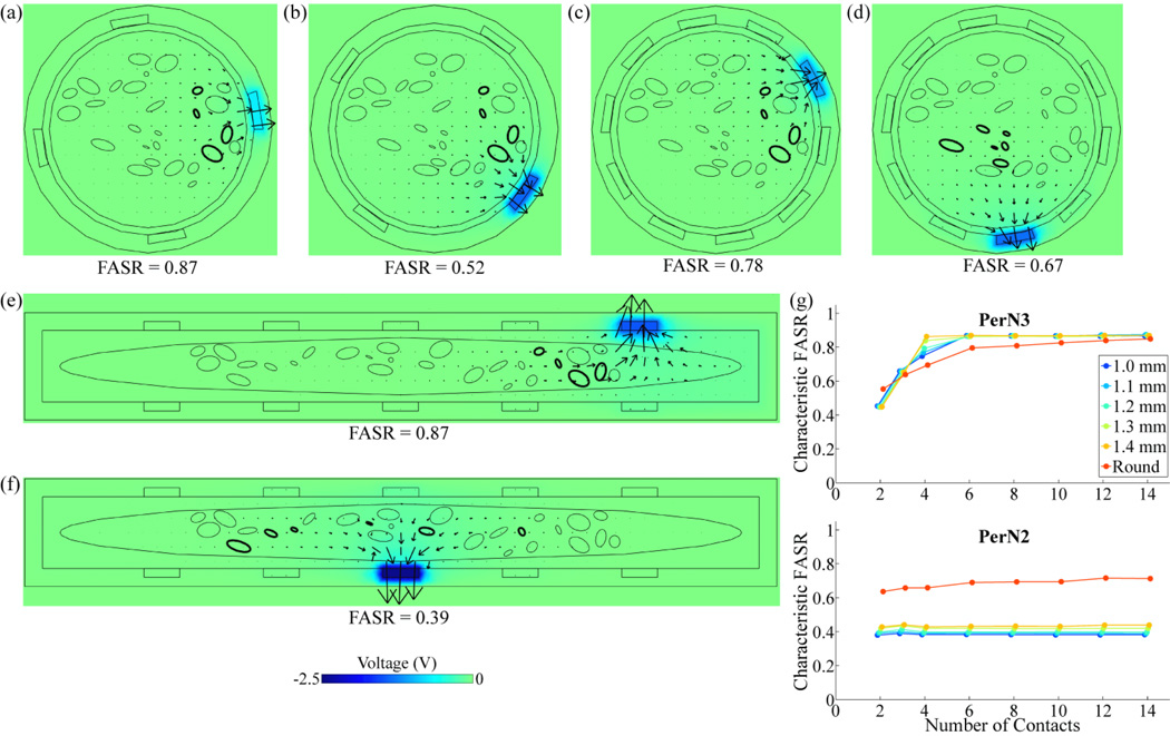
FASR values were calculated with single contact activation for the five targets (DGN, IRN, PerN1, PerN2, or PerN3) within each of the five PN trunks, across different cuff shapes, sizes, numbers of contacts, and contact orientations. For a nerve cuff with fixed shape, size, and number of contacts, one contact orientation could in some cases achieve substantially better selectivity than another orientation (figures 6(a),(b)), due to differences in the distance between a target and the closest contact, with smaller distances generally improving selectivity by reducing excitation of non-targeted axons. To account for intra-patient variation in nerve cuff placement, the FASR values across different orientations (i.e. figures 6(a) and 6(b)) were averaged to calculate the characteristic FASR value of a cuff design with given shape, size, and number of contacts.
Figure 6.
Effect of cuff design parameters on selectivity of targets within nerve 7,L. (a)-(f) Voltage and current density distributions, generated by activation of the contact that maximized target selectivity, at a transverse cross-section through the center of the nerve cuff. The boundaries of targeted fascicles are in bold. The color map indicates the voltage amplitude and the arrows indicate the direction and relative magnitude of total current density. The fascicle selectivity ratio (FASR), calculated for the contact that maximized selectivity, is shown below each plot. A round cuff with 4 contacts was used to target PerN3 with contacts in (a) the normal orientation, or (b) the staggered orientation. Similarly, a round cuff with 10 contacts in the staggered orientation was used to target (c) PerN3, or (d) PerN2. Alternatively, a FINE cuff with 1 mm height and 10 contacts in the staggered orientation was used to target (e) PerN3, or (f) PerN2. (g) Characteristic FASR value corresponding to PerN3 or PerN2 stimulation with different nerve cuff designs, including both round cuffs and FINE cuffs of various heights, across a range of total numbers of contacts.
The number of contacts, location of fascicle targets within the PN trunk, and cuff shape also affected selectivity. Increasing the number of contacts typically improved selectivity by reducing the distance between a target and the closest contact (figures 6(b),(c)). Targets located near the nerve boundary, such as PerN3 in nerve 7,L, could generally be stimulated with greater selectivity than targets located near the center of the nerve, such as PerN2 (figures 6(c),(d)). The nerve cuff shape had a variable effect on selectivity. For example, the FINE cuff moved PerN3 fascicles in nerve 7,L into a planar alignment, which increased selectivity over the round cuff (figures 6(c),(e)). Conversely, the round cuff better localized PerN2 fascicles and thereby lead to a greater FASR value than the FINE cuff, which dispersed the targeted fascicles throughout the nerve (figures 6(d),(f)). Characteristic FASRs are provided for PerN3 and PerN2 targets in nerve 7,L across all tested contact numbers, cuff shapes, and cuff sizes (figure 6(g)).
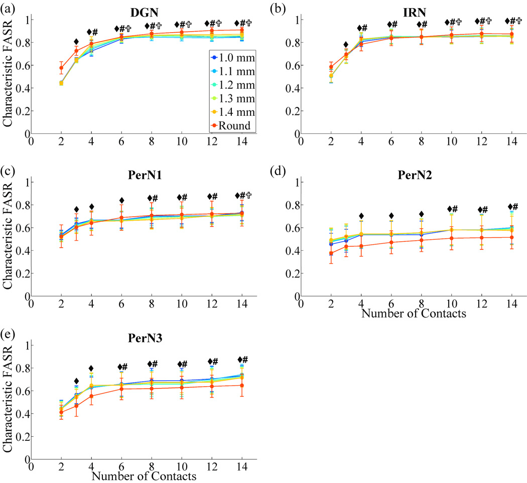
Characteristic FASRs were averaged across the five PN trunks (figure 7). For each PN target, characteristic FASR values increased with the number of contacts and plateaued. Increasing the number of contacts beyond 6 did not result in significant increases in selectivity for targeting DGN and PerN3, or beyond 10 contacts for IRN and PerN2. Increasing the number of contacts to 14, which was the maximum tested, resulted in significant improvements in selectivity only when targeting PerN1. The DGN and IRN targets could be stimulated with significantly higher selectivity than PerN2 for a nerve cuff with 6 or 8 contacts. No significant differences in FASRs were found between nerve cuff shapes, including round cuffs and FINE cuffs of different cuff heights.
Figure 7.
Effect of cuff design parameters on selectivity across the nerve population. The characteristic FASR values (mean ± SE) across the five PNs for each nerve cuff design and PN target are plotted. rmANOVA revealed the following significant factors: number of contacts (p<0.0001), contacts×cuff shape (p<0.009), contacts×target (p<0.0001). Within each PN target, number of contacts was a significant factor (p<0.002). Fisher's PLSD post-hoc tests were used to identify significant differences in characteristic FASRs between different numbers of contacts for each target: ◆, significantly different from 2 contacts; #, significantly different from 3 contacts; ✞, significantly different from 4 contacts (p<0.05).
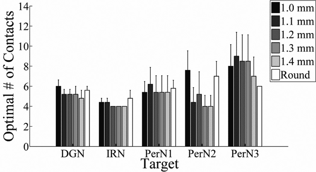
The optimal number of contacts (ONC) was calculated across cuff shapes and sizes, as well as different PN targets, and subsequently averaged across the five PN trunks (figure 8). The ONC ranged from 4 to 10 contacts, depending on the target, but differences between the ONC across targets and nerve cuff designs were not significant. Further, no significant differences across factors were found when the definition of ONC was changed from 90% of the maximum possible characteristic FASR value to 80%, 85%, or 95% of the maximum possible characteristic FASR. On average, using more than 10 contacts did not provide substantial improvements in selectivity for any target when using single contact activation.
Figure 8.
Optimal number of contacts (mean ± SE) across the five PNs for each target and with nerve cuffs of different shapes and sizes.
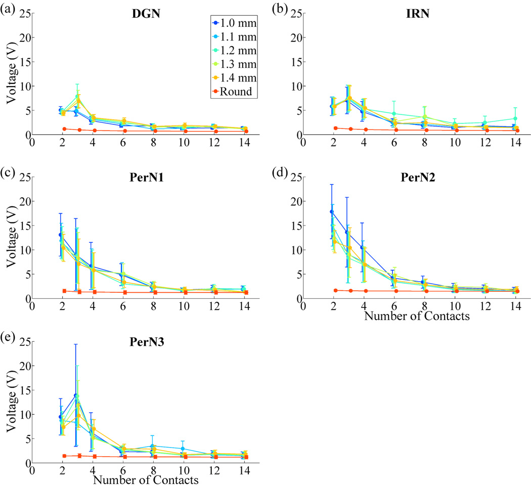
The average stimulation voltages required to stimulate each PN target were calculated across nerve cuff designs (figure 9). Voltages decreased as the number of contacts was increased before plateauing. Nerve cuffs with 2 or 3 contacts required significantly higher stimulation voltages than nerve cuffs with 4 or more contacts, and nerve cuffs with 4 contacts required higher stimulation voltages than nerve cuffs with 6 or more contacts. Further, round cuffs required significantly lower stimulation voltages than FINE cuffs of any height with 2 to 12 contacts.
Figure 9.
Effect of cuff design parameters on total stimulation voltage required for optimal selective stimulation of the PN. The stimulation voltages (mean ± SE) across the five PNs for each nerve cuff design and PN target are plotted. Global rmANOVA revealed the following significant factors: number of contacts (p<0.0001), cuff shape (p<0.0001), contacts×cuff shape (p<0.0001).
3.2 Selectivity with Multiple Contact Activation
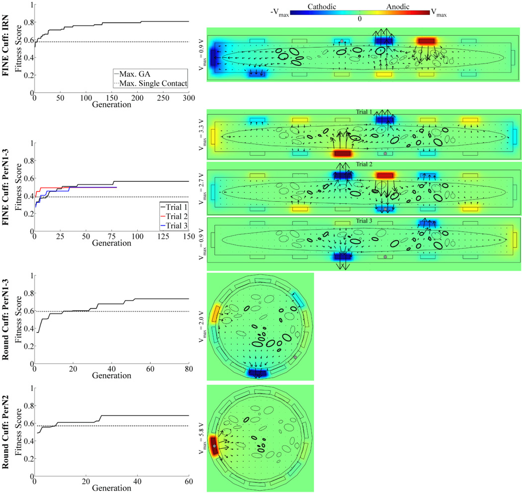
The performance of multiple contact activation surpassed that of single contact activation across PN targets and cuff designs. As the GA-based optimization progressed over generations, the fitness score increased, generally exceeding that of the single contact solution within 21 generations, before converging on a stable optimal solution in 50 to 300 generations (figure 10, left column).
Figure 10.
Optimization of multiple contact stimulation of the PN. Left: Maximum fitness score over GA generations (solid trace), shown for four different combinations of PN targets and nerve cuff designs. For comparison, the maximum fitness score for single contact activation is shown (dashed trace). Three repeated GA trials were performed for targeting of PerN1-3 with the FINE cuff, with the trials differentiated by trace color. Right: Corresponding voltage and current density distributions generated by the optimal GA solution. Data presentation is similar to that in figure 6(a)–(f), with the voltage amplitudes in each plot ranging between (−Vmax, Vmax) as indicated by the color bar legend. Additionally, the asterisks (*) identify the contacts that provided the maximal fitness score for single contact activation.
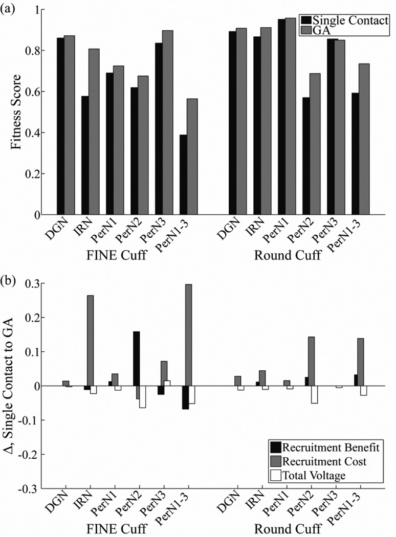
The optimal multiple contact solutions increased fitness scores by 0.7–45.5% over the single contact solutions, depending on the PN target and cuff design (figure 11(a)). The only exception was that a solution targeting PerN3 with the round cuff that had a fitness score exceeding single contact activation was not identified. The most pronounced improvements in fitness score with multiple contact activation over single contact activation were generated when stimulating IRN or PerN1-3 with the FINE cuff, in which the targeted fascicles were widely distributed through the nerve, or PerN2 or PerN1-3 with the round cuff, in which some of the targeted fascicles were located centrally within the nerve. The increase in fitness score with multiple contact activation was generally achieved through a decrease in excitation of non-targeted axons (RC), although this was partially offset by the higher voltages (figure 11(b)). Conversely, there were usually only small changes in the excitation of targeted axons (RB) with the multiple contact solutions, since the single contact solutions were already effective in this regard with a median RB value of 1 (range: 0.83–1) across PN targets and cuff designs. Comparing cuff designs with multiple contact activation, the fitness scores of the round cuff were 1.7–32.1% higher than those of the FINE cuff for all targets except PerN3, for which the round cuff fitness was 5.2% lower.
Figure 11.
Increases in selectivity achieved with optimal multiple contact stimulation. (a) Maximum fitness scores with single contact activation (black bar) and with the optimal multiple contact solution (gray bar) across PN targets and cuff designs. (b) Change in recruitment benefit, recruitment cost, and total voltage terms from equation 4 between the single contact and the optimal multiple contact solution. Note that positive values in this figure correspond to an increase in fitness score for the GA solution.
There was a common outcome resulting from the optimization to maximize the fitness score across cuff designs and PN targets. High amplitude cathode(s) were generally positioned at sites that were in close proximity to targeted fascicles, and the anodes were distributed around the cuff, typically adjacent to or across from the cathodes, to steer current predominately through targeted fascicles (figure 10, right column). However, an alternate outcome resulted for targeting of PerN2 with the round cuff, in which the centrally-located target fascicles were stimulated with a strong anode, and with weaker cathodes and anodes distributed around the cuff. The optimization trials were repeated three times for targeting of PerN1-3 with the FINE cuff, and although the solutions had different anode and cathode locations, they all followed the common contact strategy. Further, these repeated solutions had fitness scores 27.4–45.5% higher than single contact activation. Finally, every contact on the 14 contact FINE or round cuff was used at least once across PN targets, although not all contacts were necessarily active within a single solution, with an average of 11 ± 2 contacts (mean ± SD, range: 7–14) activated with amplitude greater than 1 mV.
4. Discussion
The results of this study provide a quantitative assessment of nerve cuff designs and stimulation techniques for selective stimulation of targets in the PN trunk. Increasing the number of contacts on the nerve cuff initially provided greater target selectivity and reduced stimulation voltage before eventually plateauing, and we determined that the optimal number of contacts across all PN targets was 10. FINE cuffs eliminated centrally-located fascicles, particularly with narrow cuff heights, whereas round cuffs better maintained localization of target fascicles groups and thereby required lower stimulation voltages for target activation. Multiple contact activation improved target selectivity, generating a 0.7–45.5% increase over single contact activation in the measure of fitness combining selectivity and efficiency.
4.1 Implications for Nerve Cuff Design for Selective Stimulation of the PN
Increasing the number of contacts generally improved selectivity and decreased stimulation voltage requirements by reducing the distance between targeted fascicles and the closest contact. The exception was centrally-located targets, for which increasing the total number of contacts did not produce substantial increases in selectivity (figure 6(g)). Even for peripherally-located fascicles, the addition of more contacts eventually did not lead to reductions in the target-contact distance, and selectivity and voltage requirements plateaued. One could define the optimal number of contacts as the plateauing point, above which no statistically significant increases in FASR are achieved, and this ranged from 6 to 14 contacts depending on the PN target (figure 7). However, we instead defined the optimum as that which achieved greater than 90% of the maximum characteristic FASR. Implementing additional contacts beyond this number would lead to only small improvements in selectivity while increasing the complexity and cost of nerve cuff fabrication. For example, average characteristic FASR values for DGN stimulation plateaued at 10 contacts, but 90% of the maximum characteristic FASR occurred at 4 to 6 contacts, depending on the nerve cuff shape and size. Ten contacts was the maximum optimal number of contacts across PN targets (figure 8), and led to minimal voltage requirements (figure 9). Further, using 10 contacts limited the effect of contact orientation, and therefore intra-patient cuff placement, on selectivity.
We compared the performance of FINE cuffs of different heights and round cuffs. The potential advantage of the FINE cuff is that it eliminates centrally-located fascicles, resulting in a reduction in the average distance between targets and contacts on the nerve cuff.[18] However, FINE reshaping can also reduce the localization of a targeted group of fascicles relative to the location of non-targeted fascicles (figure 3(a)), and this dispersion of target fascicles may reduce selectivity. This trade-off between target-contact distance and localization of target fascicles may have contributed to the lack of significant differences found in selectivity between different FINE cuff heights. In contrast to the FINE cuff, one advantage of the round cuff is that it maintains localization of target fascicle groups, which can reduce the volume of activation throughout the nerve. Also, all contacts on the round cuff are positioned near the nerve boundary (figure 4(b)), whereas some contacts on the FINE cuffs can be distant from the nerve boundary, such as those positioned along the cuff height dimension (figure 4(a)). Finally, round cuffs have higher contact densities (as a proportion of the nerve cuff perimeter) than any of the FINE cuffs tested. The latter two advantages would generally result in smaller distances between contacts on the round cuff and a given target, compared to the FINE cuff.
One nerve cuff shape was not distinctly more selective than another across PN targets, although the round cuff did have significantly lower voltage requirements than the FINE cuff. For nerve 7,L, the round cuff was superior in selectively stimulating nerve targets that had a large number of fascicles and which were distributed along the nerve major axis, such as PerN2 (figures 3(a), 6). Conversely, the FINE cuff was superior in stimulating targets that had a small number of fascicles, and which were distributed along the nerve minor axis, such as PerN3. However, the variation in fascicle location between different PN trunks [4] masked in the population any statistical differences between nerve cuff shapes that were observed for an individual nerve (figure 7). Nevertheless, a distinct reduction in stimulation voltage requirements was observed for the round cuff compared to FINE cuffs of any height for 2 to 12 contacts (figure 9). This resulted from the more circumscribed fascicle locations (decreased activation volumes) and generally shorter distances between target fascicles and the nearest contact. Lower voltage requirements would increase battery life, decrease the required battery size, and reduce the propensity for damage to the electrode or tissue.
The lack of differences in selectivity found between nerve cuff shapes in this study contradict prior computational [18, 35] and experimental [36] studies showing that FINE cuffs with smaller cuff heights provide greater selectivity of stimulation. One prior analysis used idealized fascicle positioning, and therefore may have resulted in different conclusions than would have been obtained with more realistic cross-sections.[18] Further, selectivity measurements in this study did not account for stimulation of a group of targeted fascicles. Another modeling study found that changes in selectivity with FINE cuff height were variable across contact numbers and stimulation targets.[35] A subsequent study suggested that cuff dimensions had a relatively small effect on selectivity compared to the number of contacts.[37] An experimental study demonstrated that a medium FINE cuff that moderately reshaped the sciatic nerve improved selectivity over a wide cuff [36], but this improvement may have resulted from the fact that the medium nerve cuff had 16 contacts whereas the wide nerve cuff had only 12 contacts. Thus, it remains unclear whether FINE cuffs with small cuff heights are the most effective design for peripheral nerve stimulation.
The selectivity of a particular cuff design depends on the target of interest. For both FINE and round cuffs with 6 or 8 contacts, DGN and IRN were stimulated with significantly greater selectivity than PerN2 across PN trunks (figure 7). This resulted from the location of these targets within the PN trunk, with DGN and IRN typically located at the periphery and PerN2 located more centrally. Further, the average characteristic FASR for the DGN and IRN targets was greater than for PerN1 and PerN3 targets, although these differences were not statistically significant. Nevertheless, these results indicate that a nerve cuff on the PN trunk may be more effective in selective stimulation of the DGN and IRN than selective stimulation of PerN targets.
This finding bodes well for a therapeutic approach using stimulation of the DGN within the PN trunk alone for both maintaining continence and generating micturition. Stimulation of the DGN branch at low frequencies (5 to 10 Hz) inhibits contractions of the bladder and thereby maintains continence, whereas higher stimulation frequencies (30 to 40 Hz) generate bladder contractions and facilitate micturition.[12] The DGN fascicles are typically located near the nerve periphery (figure 3(a)), enabling higher selectivity (figure 7). Further, these fascicles have consistent locations among different PN trunks [4], which could simplify inter-patient surgical and programming procedures. Using this treatment method, the number of contacts on the nerve cuff could be reduced to six, as no significant improvement in DGN selectivity was generated with additional contacts (figure 7), and this was the maximum value for the optimal number of contacts for DGN stimulation (figure 8).
4.2 Multiple Contact Activation Improves Selectivity
An optimization approach was used to quantify the potential improvement in performance with simultaneous activation of multiple contacts using FINE and round cuffs with 14 contacts. Performance was evaluated using a fitness score that rewarded PN target selectivity and penalized total stimulation voltage. Implementing this approach using cuff designs with the maximal 14 contacts provided the greatest number of potential combinations of activated contacts, thereby increasing the likelihood of identifying a solution that could selectively stimulate the targeted fascicles. This was validated by the findings that every contact was activated for at least one PN target, and that an average of 11 ± 2 contacts were activated across the solutions. Although the round cuff performed better than the FINE cuff with multiple contact activation for all targets except PerN3 (figure 11(a)), it is unclear if this trend would hold across different PN trunks with variable fascicle locations.
The optimization revealed a common outcome for contact activation to improve the performance of a given cuff design. Appropriate placement of strong cathode(s) near the target fascicles and anodes adjacent to or across from the cathode(s) increased selectivity of the target fascicles (figure 10). However, the tradeoff was a higher voltage requirement for optimal solutions (figure 11(b)), which was driven by the low weighting factor in the fitness voltage term (equation 4). If optimization was repeated with a higher weighting of the voltage term, then the solutions would likely have shifted towards using lower voltages at the expense of selectivity.
The greatest improvements in selectivity with multiple contact activation were observed when target fascicles were distributed throughout the nerve or located centrally within the nerve. In these cases, using a single voltage source resulted in greater activation of non-targeted fascicles. Multiple contact activation was more effective in stimulating multiple, dispersed fascicle groups, such as PerN1-3. Nevertheless, the solutions for PerN1-3 stimulation identified with three repeated optimization trials varied, indicating that there may be several different combinations of contact activation that maximize selectivity. In situations where the target fascicles were located centrally, such as PerN2 with the round cuff, the optimization results suggested that using a high amplitude anode would provide maximum performance. This may be due to a shifting of the region of excitation away from nearby, non-targeted fascicles along the nerve perimeter.[38] Finally, the GA was least effective in identifying solutions superior to single contact activation when targeting PerN3 with the round cuff. This likely resulted from the grouping of PerN3 and DGN fascicles in very close proximity (figure 3(a)), such that co-activation of DGN fascicles was unavoidable, even with multiple contact activation.
There are several considerations for clinical translation of the multiple contact activation approach. First, it is unlikely that access to the nerve anatomy, including fascicle locations and fascicle-branch relationships, will be available. Since this information is critical to identifying a high performing multiple contact solution with the GA, we suggest that a preliminary inverse mapping technique is performed. This would entail applying stimulation at each contact in-turn to determine the approximate location of excitatory and inhibitory axons, based on the physiological responses as measured with pelvic floor electromyogram(s) and bladder pressure. An approximation of the nerve cross-section could then be reconstructed within the GA model to determine effective stimulation configurations. Second, our GA assumed independent control of stimulation voltage at each of the 14 contacts, which would require a 14- channel implanted pulse generator. Using fewer contacts or coupling the contacts could simplify clinical implantation, reduce lead stiffness, and thereby decrease the risk of tissue damage [37], although at the cost of a reduction in selectivity.
4.3 Study Limitations
The model-based analysis and optimization provided insight into nerve cuff designs and stimulation methods that maximized selectivity, but there were several assumptions, particularly in the anatomical representation of the PN trunk. First, it was assumed that the fascicular structure was constant over the length of the proximal PN trunk targeted for nerve cuff implantation. This is accurate over a short length of the PN trunk, such as the 5 mm length under the nerve cuff, but may not be true over the entire 25 mm nerve length used in this study.[4] Second, the nerve and fascicle boundaries were assumed to be elliptical to improve FEM meshing performance. However, since fascicle boundaries are already roughly elliptical in the PN trunk (figure 3(a)), this transformation amounted to boundary smoothing, which would have a minimal effect on the calculated FEM potentials. Third, all axons in the PN trunk had a constant diameter of 7.2 µm, rather than a range of diameters between 2 – 18 µm, as typically found in peripheral nerves.[39] Fourth, the number of axons per fascicle was constant at twenty, instead of being proportional to fascicle size.[40] However, these last two assumptions are acceptable because the modeled axons are intended to be representative for detection of fascicle stimulation, rather than a means to measure intra-fascicle stimulation.
Another assumption that was made in this model was that all axons in every fascicle corresponding to a particular target needed to be stimulated to achieve a functional response for single contact activation. Conversely, an investigation into nerve cuff stimulation of the sciatic nerve indicated that complete stimulation of targeted fascicles was not required to get sufficient muscle recruitment for sit-to-stand and gait movements.[35] The responses generated by PN stimulation may operate similarly, in which case greater selectivity of targets could be obtained by focusing stimulation on targeted fascicles that are distant from non-targeted fascicles. In addition, it was assumed that the recruitment cost should be weighted equally for stimulation of all non-targeted fascicles. However, it may be clinically valuable to adjust weights according to whether concomitant stimulation of non-targeted fascicles generates similar or opposing functional outputs.
Acknowledgements
The work was supported by NIH R01 NS050514 and the Medtronic Foundation Fellowship from the Duke University Department of Biomedical Engineering. The authors would like to thank Patrick Ye and Siddhartha Kosaraju for their assistance on development of the genetic algorithm. They would also like to acknowledge the Duke Shared Cluster Computing Resource.
References
- 1.Watanabe T, Rivas DA, Chancellor MB. Urodynamics of spinal cord injury. Urol Clin North Am. 1996;23:459–473. doi: 10.1016/s0094-0143(05)70325-6. [DOI] [PubMed] [Google Scholar]
- 2.Shingleton WB, Bodner DR. The development of urologic complications in relationship to bladder pressure in spinal cord injured patients. J Am Paraplegia Soc. 1993;16:14–17. doi: 10.1080/01952307.1993.11735878. [DOI] [PubMed] [Google Scholar]
- 3.Grill WM, Craggs MD, Foreman RD, Ludlow CL, Buller JL. Emerging clinical applications of electrical stimulation: opportunities for restoration of function. J Rehabil Res Dev. 2001;38:641–653. [PubMed] [Google Scholar]
- 4.Gustafson KJ, Zelkovic PF, Feng AH, Draper CE, Bodner DR, Grill WM. Fascicular anatomy and surgical access of the human pudendal nerve. World J Urol. 2005;23:411–418. doi: 10.1007/s00345-005-0032-4. [DOI] [PubMed] [Google Scholar]
- 5.Godec C, Cass AS, Ayala GF. Bladder inhibition with functional electrical stimulation. Urology. 1975;6:663–666. doi: 10.1016/0090-4295(75)90791-8. [DOI] [PubMed] [Google Scholar]
- 6.Wheeler JS, Jr, Walter JS, Zaszczurynski PJ. Bladder inhibition by penile nerve stimulation in spinal cord injury patients. J Urol. 1992;147:100–103. doi: 10.1016/s0022-5347(17)37145-8. [DOI] [PubMed] [Google Scholar]
- 7.Wheeler JS, Jr, Walter JS, Sibley P. Management of incontinent SCI patients with penile stimulation: preliminary results. J Am Paraplegia Soc. 1994;17:55–59. doi: 10.1080/01952307.1994.11735917. [DOI] [PubMed] [Google Scholar]
- 8.Kirkham AP, Shah NC, Knight SL, Shah PJ, Craggs MD. The acute effects of continuous and conditional neuromodulation on the bladder in spinal cord injury. Spinal Cord. 2001;39:420–428. doi: 10.1038/sj.sc.3101177. [DOI] [PubMed] [Google Scholar]
- 9.Lee YH, Creasey GH, Lim H, Song J, Song K, Kim J. Detrusor and blood pressure responses to dorsal penile nerve stimulation during hyperreflexic contraction of the bladder in patients with cervical cord injury. Arch Phys Med Rehabil. 2003;84:136–140. doi: 10.1053/apmr.2003.50075. [DOI] [PubMed] [Google Scholar]
- 10.Yoo PB, Klein SM, Grafstein NH, Horvath EE, Amundsen CL, Webster GD, Grill WM. Pudendal nerve stimulation evokes reflex bladder contractions in persons with chronic spinal cord injury. Neurourol Urodyn. 2007;26:1020–1023. doi: 10.1002/nau.20441. [DOI] [PubMed] [Google Scholar]
- 11.Yoo PB, Woock JP, Grill WM. Bladder activation by selective stimulation of pudendal nerve afferents in the cat. Exp Neurol. 2008;212:218–225. doi: 10.1016/j.expneurol.2008.04.010. [DOI] [PMC free article] [PubMed] [Google Scholar]
- 12.Woock JP, Yoo PB, Grill WM. Activation and inhibition of the micturition reflex by penile afferents in the cat. Am J Physiol Regul Integr Comp Physiol. 2008;294:R1880–R1889. doi: 10.1152/ajpregu.00029.2008. [DOI] [PMC free article] [PubMed] [Google Scholar]
- 13.Tai C, Chen M, Shen B, Wang J, Liu H, Roppolo JR, de Groat WC. Plasticity of urinary bladder reflexes evoked by stimulation of pudendal afferent nerves after chronic spinal cord injury in cats. Exp Neurol. 2011;228:109–117. doi: 10.1016/j.expneurol.2010.12.016. [DOI] [PMC free article] [PubMed] [Google Scholar]
- 14.Grill WM, Mortimer JT. Quantification of recruitment properties of multiple contact cuff electrodes. IEEE Trans Rehabil Eng. 1996;4:49–62. doi: 10.1109/86.506402. [DOI] [PubMed] [Google Scholar]
- 15.Veraart C, Grill WM, Mortimer JT. Selective control of muscle activation with a multipolar nerve cuff electrode. IEEE Trans Biomed Eng. 1993;40:640–653. doi: 10.1109/10.237694. [DOI] [PubMed] [Google Scholar]
- 16.Tyler DJ, Durand DM. Functionally selective peripheral nerve stimulation with a flat interface nerve electrode. IEEE Trans Neural Syst Rehabil Eng. 2002;10:294–303. doi: 10.1109/TNSRE.2002.806840. [DOI] [PubMed] [Google Scholar]
- 17.Leventhal DK, Durand DM. Subfascicle stimulation selectivity with the flat interface nerve electrode. Ann Biomed Eng. 2003;31:643–652. doi: 10.1114/1.1569266. [DOI] [PubMed] [Google Scholar]
- 18.Choi AQ, Cavanaugh JK, Durand DM. Selectivity of multiple-contact nerve cuff electrodes: a simulation analysis. IEEE Trans Biomed Eng. 2001;48:165–172. doi: 10.1109/10.909637. [DOI] [PubMed] [Google Scholar]
- 19.Tyler DJ, Durand DM. Chronic response of the rat sciatic nerve to the flat interface nerve electrode. Ann Biomed Eng. 2003;31:633–642. doi: 10.1114/1.1569263. [DOI] [PubMed] [Google Scholar]
- 20.Polasek KH, Hoyen HA, Keith MW, Kirsch RF, Tyler DJ. Stimulation stability and selectivity of chronically implanted multicontact nerve cuff electrodes in the human upper extremity. IEEE Trans Neural Syst Rehabil Eng. 2009;17:428–437. doi: 10.1109/TNSRE.2009.2032603. [DOI] [PMC free article] [PubMed] [Google Scholar]
- 21.Brill N, Tyler D. Optimizing Nerve Cuff Stimulation of Targeted Regions Through Use of Genetic Algorithms; Conf Proc IEEE Eng Med Biol Soc; 2011. pp. 5811–5814. [DOI] [PubMed] [Google Scholar]
- 22.Grill WM, Mortimer JT. Neural and connective tissue response to long-term implantation of multiple contact nerve cuff electrodes. J Biomed Mater Res. 2000;50:215–226. doi: 10.1002/(sici)1097-4636(200005)50:2<215::aid-jbm17>3.0.co;2-a. [DOI] [PubMed] [Google Scholar]
- 23.Weerasuriya A, Spangler RA, Rapoport SI, Taylor RE. AC impedance of the perineurium of the frog sciatic nerve. Biophys J. 1984;46:167–174. doi: 10.1016/S0006-3495(84)84009-6. [DOI] [PMC free article] [PubMed] [Google Scholar]
- 24.Geddes LA, Baker LE. The specific resistance of biological material--a compendium of data for the biomedical engineer and physiologist. Med Biol Eng. 1967;5:271–293. doi: 10.1007/BF02474537. [DOI] [PubMed] [Google Scholar]
- 25.Ranck JB, Jr, Bement SL. The specific impedance of the dorsal columns of cat: an inisotropic medium. Exp Neurol. 1965;11:451–463. doi: 10.1016/0014-4886(65)90059-2. [DOI] [PubMed] [Google Scholar]
- 26.Grill WM, Mortimer JT. Electrical properties of implant encapsulation tissue. Ann Biomed Eng. 1994;22:23–33. doi: 10.1007/BF02368219. [DOI] [PubMed] [Google Scholar]
- 27.Oxtoby DW, Gillis HP, A C. Principles of Modern Chemistry. Belmont, CA: Brooks/Cole; 2011. [Google Scholar]
- 28.Grinberg Y, Schiefer MA, Tyler DJ, Gustafson KJ. Fascicular perineurium thickness, size, and position affect model predictions of neural excitation. IEEE Trans Neural Syst Rehabil Eng. 2008;16:572–581. doi: 10.1109/TNSRE.2008.2010348. [DOI] [PMC free article] [PubMed] [Google Scholar]
- 29.Ranck JB., Jr Specific impedance of rabbit cerebral cortex. Exp Neurol. 1963;7:144–152. doi: 10.1016/s0014-4886(63)80005-9. [DOI] [PubMed] [Google Scholar]
- 30.Hines ML, Carnevale NT. The NEURON simulation environment. Neural Comput. 1997;9:1179–1209. doi: 10.1162/neco.1997.9.6.1179. [DOI] [PubMed] [Google Scholar]
- 31.Sweeney JD, Mortimer JT, Durand DM. Modeling of mammalian myelinated nerve for functional neuromuscular stimulation; Conf Proc IEEE Eng Med Biol Soc; 1987. pp. 1577–1578. [Google Scholar]
- 32.McIntyre CC, Grill WM. Sensitivity analysis of a model of mammalian neural membrane. Biol Cybern. 1998;79:29–37. doi: 10.1007/s004220050455. [DOI] [PubMed] [Google Scholar]
- 33.Warman EN, Grill WM, Durand D. Modeling the effects of electric fields on nerve fibers: determination of excitation thresholds. IEEE Trans Biomed Eng. 1992;39:1244–1254. doi: 10.1109/10.184700. [DOI] [PubMed] [Google Scholar]
- 34.Wongsarnpigoon A, Grill WM. Energy-efficient waveform shapes for neural stimulation revealed with a genetic algorithm. J Neural Eng. 2010;7:046009. doi: 10.1088/1741-2560/7/4/046009. [DOI] [PMC free article] [PubMed] [Google Scholar]
- 35.Schiefer MA, Triolo RJ, Tyler DJ. A model of selective activation of the femoral nerve with a flat interface nerve electrode for a lower extremity neuroprosthesis. IEEE Trans Neural Syst Rehabil Eng. 2008;16:195–204. doi: 10.1109/TNSRE.2008.918425. [DOI] [PMC free article] [PubMed] [Google Scholar]
- 36.Leventhal DK, Durand DM. Chronic measurement of the stimulation selectivity of the flat interface nerve electrode. IEEE Trans Biomed Eng. 2004;51:1649–1658. doi: 10.1109/TBME.2004.827535. [DOI] [PubMed] [Google Scholar]
- 37.Schiefer MA, Tyler DJ, Triolo RJ. Probabilistic modeling of selective stimulation of the human sciatic nerve with a flat interface nerve electrode. J Comput Neurosci. 2012;33:179–190. doi: 10.1007/s10827-011-0381-5. [DOI] [PMC free article] [PubMed] [Google Scholar]
- 38.Tarler MD, Mortimer JT. Selective and independent activation of four motor fascicles using a four contact nerve-cuff electrode. IEEE Trans Neural Syst Rehabil Eng. 2004;12:251–257. doi: 10.1109/tnsre.2004.828415. [DOI] [PubMed] [Google Scholar]
- 39.Boyd IA, Davey MR. Composition of Peripheral Nerves. London: E&S Livingstone, Ltd.; 1968. [Google Scholar]
- 40.Saxod R, Torch S, Vila A, Laurent A, Stoebner P. The density of myelinated fibres is related to the fascicle diameter in human superficial peroneal nerve. Statistical study of 41 normal samples. J Neurol Sci. 1985;71:49–64. doi: 10.1016/0022-510x(85)90036-x. [DOI] [PubMed] [Google Scholar]


