Abstract
The objective of this study is to investigate the effect of device design of the Aerolizer® on the aerosolization of a carrier-based dry powder inhaler formulation (Foradile®). The Aerolizer was modified by reducing the air inlet size and mouthpiece length to 1/3 of the original dimensions, or by increasing the grid voidage. Aerosolization of the powder formulation was assessed on a multi-stage liquid impinger at air flow rates of 30, 60, and 100 L/min. Coupled CFD-DEM simulations were performed to investigate the air flow pattern and particle impaction. There was no significant difference in the aerosolization behavior between the original and 1/3 mouthpiece length devices. Significant increases in FPF total and FPF emitted were demonstrated when the inlet size was reduced, and the results were explained by the increases in air velocity and turbulence from the CFD analysis. No significant differences were shown in FPF total and FPF emitted when the grid voidage was increased, but more drugs were found to deposit in induction port and to a lesser extent, the mouthpiece. This was supported by the CFD-DEM analysis which showed the particle–device collisions mainly occurred in the inhaler chamber, and the cross-grid design increased the particle–device collisions on both mouthpiece and induction port. The air inlet size and grid structure of the Aerolizer® were found to impact significantly on the aerosolization of the carrier-based powder.
Key words: aerosolization, computational fluid dynamics, device design, discrete element method, dry powder inhalers
INTRODUCTION
Aerosols generated by dry powder inhalers (DPIs) are among the most promising forms to deliver therapeutic agents by inhalation to the lungs (1). DPI powders are commonly formulated as a mixture of micronized drug particles and coarse carriers. Over the last decades, extensive research has been performed to study the influence of formulation design on the aerosolization of DPIs (2). However, the effects of device design on DPI aerosolization are much less studied (3).
Performance of DPI depends on many variables including formulation design, device selection, environment, and patients’ inhalation (3). The design of inhaler device plays a critical role on the aerosolization of the DPI formulations. The effect of air turbulence on the in vitro DPI performance of carrier-based albuterol sulfate powders was investigated experimentally using a powder de-agglomeration rig (4). Powder de-agglomeration was improved as the air turbulence was increased for the carrier-based DPI formulation (4). Coates et al. have investigated the effect of grid structure, mouthpiece length (5), inlet size (6), and mouthpiece geometry (7) of the Aerolizer® on the de-agglomeration of mannitol powders as a drug-only formulation. Experimental studies coupled with computational fluid dynamics (CFD) analysis were employed in this series of studies to simulate the flow field generated in the device with the purpose to better understand the effect of device design on de-agglomeration. Most recently, CFD analysis was also employed to investigate the effect of carrier properties on the aerosolization (8) and in vitro comparability of two capsule-based devices (9) for the carrier-based DPIs. However, CFD analysis can only simulate the air flow pattern and is unable to take particle interactions into account. Recently, CFD has been successfully coupled with the discrete element method (DEM) to understand the particle deposition behavior during aerosolization because both air flow and particle interactions are calculated (10). There is still a lack of systemic investigation of the effect of device design on the aerosol performance of carrier-based DPI systems.
In the present study, the influence of grid structure, inlet size, and mouthpiece length of the Aerolizer on the aerosolization of a carrier-based DPI formulation was examined experimentally. The CFD-DEM simulations were performed to understand the flow field in the inhaler devices, their potential effects on powder de-agglomeration and the particle impactions with inhaler and induction port walls. A marketed eformoterol fumarate dihydrate powder formulation (Foradile®) was used in this study as it is commercially manufactured for use with the Aerolizer.
MATERIALS AND METHODS
Materials
Similar to our previous studies on drug-only powder systems (5,6), the Aerolizer was modified to (1) reduce mouthpiece length to 1/3 of the original; (2) reduce air inlet size to 1/3 of the original; and (3) replace the original grid mesh with a cross-grid one with a higher voidage (Fig. 1). The prototype original and modified inhalers were manufactured by Plastiape S.p.A. (Osnago, Italy) using a methyl methacrylate acrylonitrile butadiene styrene resin by injection-molding machines (Arburg, Loßburg, Germany). The modification was performed according to the proposed designs: (1) shorter mouthpieces were obtained by reducing the original mouthpiece length using a milling machine (model LW-2VHT, L & W machine tools Inc, Fenyuan, Taiwan); (2) different sizes of the mouthpiece grid were obtained using a simple purpose made cutting tool, starting from the original grid and removing parts of it according to the proposed designs; (3) different sizes of the air inlet were obtained starting from the standard air inlet, reducing its dimension by manually adding epoxy resin, and reworking it using a milling machine according to the proposed design.
Fig. 1.
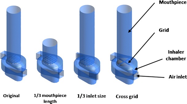
Diagram of the original and modified Aerolizer devices
Foradile® capsules (Batch Number U0021, Novartis Pharmaceuticals Australia Pty Limited, North Ryde, NSW, Australia) were obtained from a pharmacy. Each capsule contains a labeled dose of 12 μg eformoterol fumarate dihydrate and approximately 24 mg of lactose. Methanol (high-performance liquid chromatography (HPLC) grade) was purchased from Fisher Scientific (Fair Lawn, New Jersey, USA) and acetic acid from BDH Laboratory Supplies (Poole, UK).
Experimental Methods
Characterization of Physico-Chemical Properties
Particle size distributions of the Foradile® powder were measured by laser diffraction (Mastersizer 2000, Malvern Instruments, Worcestershire, UK) with a Scirocco dry powder module. The powders were dispersed through the measurement window with compressed air (11). The d50 (diameter at 50% undersize), d10 (diameter at 10% undersize), and d90 (diameter at 90% undersize) were calculated from the size distribution data. The measurement was conducted in triplicate.
Scanning electron microscopy (SEM) was employed to investigate the particle morphology of the Foradile® powder. Samples were sprinkled on a carbon sticky tape and mounted on a SEM stubs, followed by sputter coating with gold (15 nm thick) by a K550X sputter coater (Quorum Emitech, Kent, UK). The images were captured using a field emission SEM (Zeiss Ultra Plus, Carl Zeiss SMT AG, Oberkochen, Germany) at 5 kV.
X-ray powder diffraction (XRD; Shimadzu XRD-6000, Shimadzu Corporation, Kyoto, Japan) was employed to evaluate crystallinity of the powders. Cu-Kα radiation at a generator voltage of 40 kV and a current of 30 mA was used. The data was acquired using an incident beam angle of 1° and a scan speed of 2°/min at 0.02° step angle in the range of 5–80°.
In Vitro Aerosolization
The in vitro aerosol performance was determined by a multi-stage liquid impinger (Apparatus C, British Pharmacopeia 2012, Copley, Nottingham, UK) with a USP induction port. All dispersion experiments were performed at ambient temperature of 20 ± 3°C and relative humidity of 50 ± 3%. The air flow rate was adjusted to 30, 60, or 100 L/min by a flow meter (Model 3063, TSI Incorporated, MN, USA). The cut-off aerodynamic diameter of stages 1–4 at flow rate of 60 L/min are 13.3, 6.7, 3.2, and 1.7 μm, respectively. The cut-off diameter of the impinger stages at different air flow rates can be calculated as being inversely proportional to the square root of the flow rate (12). The dispersion times at different flow rates were 8, 4, and 2.4 s at 30, 60, and 100 L/min, respectively, allowing 2.4 L of air pass the inhaler. Three Foradile® capsules were used without device cleaning in between for each measurement to generate a sufficient concentration for drug assay. Triplicate measurements were carried out for each device. Drug deposited on capsule, inhaler body, inhaler mouthpiece, USP induction port, stages 1–4, and filter was collected using a liquid consisting of methanol and water (volumetric ratio of 55:45) (13). The emitted dose was calculated as the percentage of the drug emitted from the capsules and inhaler device during the aerosolization. The fine particle fraction of total drug load (FPF total) was calculated as the percentage of drug particles with an aerodynamic diameter <5 μm in the aerosol relative to the total drug loaded to the inhaler. The fine particle fraction of emitted dose (FPF emitted) was defined as the percentage of drug particles <5 μm in the emitted aerosol.
Chemical Assay
The drug content of eformoterol fumarate dihydrate was assayed using a high-performance liquid chromatography system (Model LC-20, Shimadzu, Kyoto, Japan). The HPLC system consists of a CBM-20A controller, LC-20AT pump, SPD-20A UV/VIS detector, SIL-20A HT autosampler, LCSolution software (all from Shimadzu, Kyoto, Japan) and a LiChrosphere 60 RP-select B column (4 × 125 mm, 5 μm, Merck, Darmstadt, Germany) (13). The UV absorbance wavelength of 230 nm was used for the detection of drug. The mobile phase consisted of methanol, water, and acetic acid (550:450:1) (14). The flow rate was 1 mL/min and the retention time 4.9 min for eformoterol fumarate dihydrate. A known amount of drug was dissolved in methanol and diluted with the collecting solvent of methanol and water (55:45) into different concentrations for the calibration solutions. The calibration curve was linear in the concentration range of 0.05–1 mg/mL (R2 = 0.9999, n = 3). The precision was <2% for sampling repeatability and <0.1% for injection repeatability (n = 6). The accuracy was in the range of 98–102% (n = 6).
The content of lactose was also measured using high-performance liquid chromatography (Model LC-20, Shimadzu, Kyoto, Japan) with a refractive index detector (RID-10A, Shimadzu, Kyoto, Japan) and a Resolve™ C18 column (3.9 × 150 mm, 5 μm, Waters Corporation, Milford, Massachusetts, USA) at 1 mL/min. The calibration solutions were produced in the concentration range of 0.1–5 mg/mL (R2 = 0.9996, n = 3).
CFD-DEM Modeling
The CFD-DEM simulations were performed on all cases including the original and modified Aerolizers with the UPS induction port. The description of CFD-DEM model has been detailed in previous work (10,15) and was only summarized here. By treating the dispersion process as a particle–fluid flow, the discrete particles and the continuous air flow were modeled by DEM and CFD, respectively. In the DEM model, the motions of a particle (of mass mi and radius Ri) are governed by Newton’s second law of motion (15). The inter-particle forces include the contact force, damping force and the van der Waals force. Other forces are the gravitational force and the particle–fluid interaction force (15). The commercial CFD software Fluent® was used to simulate fluid flow which is governed by the Navier–Stokes equations. The Reynolds stress model was adopted for the turbulent flow of gas as the model has been demonstrated to be suitable for the swirl flow (16,17). The dynamic mesh model was used to model the spinning capsule. The CFD-DEM coupling was achieved by combining DEM with Fluent® through its user defined functions. At each time step, based on fluid flow field, DEM calculated particle-related information based on fluid flow field, such as the positions and velocities of individual particles, to determine porosity and volumetric particle–fluid interaction force in the individual computational cells. CFD then used these data to determine the air flow field which then yielded the particle–fluid interaction forces acting on individual particles. Incorporation of the resulting forces into DEM produced information about the motion of individual particles for the next time step, and the process continued (18).
In the simulations, a velocity inlet and a pressure outlet boundary conditions were used. The normalized Reynolds stress residuals in the range of 10−4 were applied as the convergence criteria to ensure full convergence. Three grid domains were tested in the preliminary computation and the difference was less than 5% for all variables examined, indicating that the results were mesh independent (10).
Statistic Analysis
The statistic analysis was performed using independent Student t test or one way analysis of variance with probability values of less than 0.05 considered as significant difference.
RESULTS
Physico-Chemical Properties
The Foradile particles exhibited irregularly angular shape with sharp edges (Fig. 2). The majority of particles (most likely lactose) had the diameter in the range of 30–70 μm. Fine particles can be observed on the coarse particle surfaces. The XRD peaks (data not shown) showed the characteristics of crystalline α-monohydrate lactose. Particle sizing data confirmed these particles had a d50 of 54.4 ± 0.8 μm (d10 = 6.4 ± 0.1 μm and d90 = 170.1 ± 4.4 μm). As the concentration of eformoterol fumarate is around only 0.05% w/w in the Foradile powder, it will have negligible contribution in the XRD and particle sizing measurements.
Fig. 2.
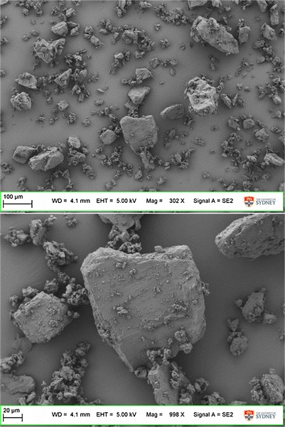
Scanning electron microscopy images of Foradile particles
In Vitro Aerosolization
Reducing the air inlet to 1/3 size of the original design produced no change in the emitted dose (p > 0.05) at 60 L/min, while the FPF total was increased significantly from 17.7 ± 0.5% to 24.3 ± 0.5% and FPF emitted increased significantly from 22.7 ± 0.9% to 31.3 ± 1.0% (p < 0.001; Fig. 3a). Such increases in the FPF were due to less drug particles being deposited on stage 1 while significantly more drugs deposited on the impinger stages 3 and 4, and filter using the 1/3 inlet size device (p < 0.05; Fig. 3b). These results indicated that a smaller air inlet enhances the detachment of drug particles from the carrier surfaces followed by deposition on the lower stages of the impinger during aerosolization. Similar trends on drug aerosolization are observed at the other flow rates (30 and 100 L/min; Figs. 4 and 5), except at the higher flow a higher emitted dose (p < 0.05) was produced (Fig. 5a).
Fig. 3.
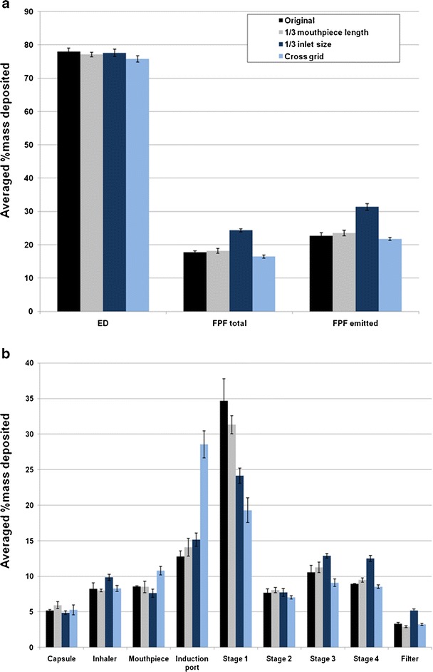
Effect of Aerolizer design on a in vitro aerosol performance and b aerosol deposition on each stage of the multi-stage impinger at 60 L/min (n = 3)
Fig. 4.
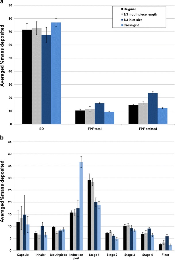
Effect of Aerolizer design on a in vitro aerosol performance and b aerosol deposition on each stage of the multi-stage impinger at 30 L/min (n = 3)
Fig. 5.
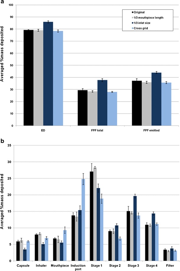
Effect of Aerolizer design on a in vitro aerosol performance and b aerosol deposition on each stage of the multi-stage impinger at 100 L/min (n = 3)
Between the original device and the cross-grid design, there was no significant difference in the FPF total and FPF emitted at all three flow rates (p > 0.05; Figs. 3a, 4a, and 5a). However, for stage 1, induction port and mouthpiece, significant differences were found (p < 0.05; Fig. 3b). At 60 L/min, the drug deposited in the induction port was more than double for the cross-grid device with an increase from 12.8 ± 0.8% to 28.6 ± 1.9% (p < 0.001). In contrast, the drug deposition on the stage 1 for the cross-grid is only half of the amount compared to the original device with a reduction from 34.7 ± 3.1% to 19.3 ± 1.8% (p < 0.001). Such profoundly enhanced drug deposition in the induction port along with reduction in the stage 1 for the cross-grid device was also shown at the other flow rates of 30 and 100 L/min (p < 0.05).
Reducing the mouthpiece length to 1/3 of the original design did not produce any significant effect on the drug deposition patterns and aerosol performance at any flow rate (p > 0.05; Figs. 3, 4, and 5).
Capsule retention of the powder in each of the device at 30 L/min was significantly greater than those at 60 and 100 L/min (p < 0.05), but further increase of the flow rate from 60 to 100 L/min did not affect the capsule retention (p > 0.05). There was no significant difference in capsule retention among the four devices at 30 and 60 L/min (p > 0.05). At 100 L/min, the capsule retention of the 1/3 inlet size was significantly lower than those of the other three devices, but no significant difference was observed among the original, 1/3 mouthpiece and cross-grid devices.
Model Analysis of Flow Field
Figure 6a showed the simulated flow fields for different designs. The 1/3 mouthpiece and cross-grid designs had similar velocity patterns in the inhaler chamber compared to the original Aerolizer at 60 L/min. In contrast, reducing the air inlet to 1/3 size of the original design resulted in much higher velocity inside the swirling chamber.
Fig. 6.
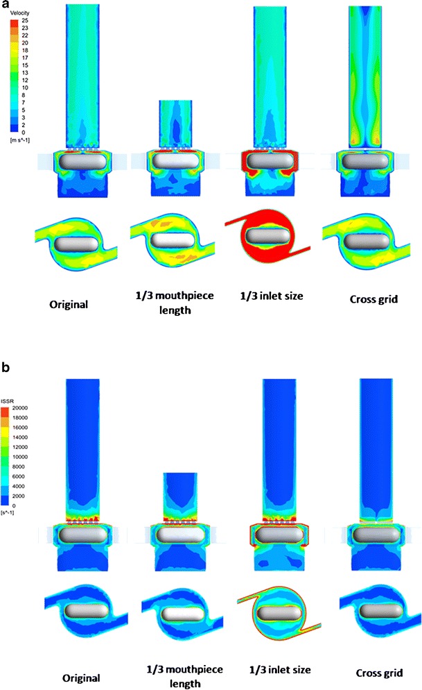
Contour of air flow velocity (a) and ISSR (b) in the original and modified Aerolizers at 60 L/min
Figure 6b showed the spatial distribution of the integral scale strain rate (ISSR) in the original and modified Aerolizers at 60 L/min. ISSR is a measure of the velocity gradient across the integral scale eddies (the most energetic occurring in a turbulence flow) (10), given by
 |
1 |
where ui is the integral velocity scale, l the integral length scale, ε the rate of turbulence eddy dissipation, and k the turbulence kinetic energy. ISSR has been demonstrated to be more relevant to agglomerate dispersion (19). Turbulent flow consisting of eddies that exhibit larger ISSR exerts larger aerodynamic forces on particles and hence is more effective in powder dispersion. ISSR had maximum values near the spinning capsule, grid, and inhaler chamber wall (Fig. 6b). Similar to the velocity profile, only the 1/3 inlet size of the original design resulted in higher ISSR inside the inhaler chamber.
Figure 7 showed the velocity contour and the streamline of air flow in the original and cross-grid designs coupled to the USP induction port. The streamlines are a family of curves that are instantaneously tangent to the velocity vector of the flow. These show the direction that a fluid element travels in at any point in time. Increasing the voidage of the grid was found to produce a more swirling flow in the mouthpiece (5). The present study showed the swirling flow was also extended from the mouthpiece into the induction port, although at a reduced velocity as the induction port was wider than the mouthpiece.
Fig. 7.
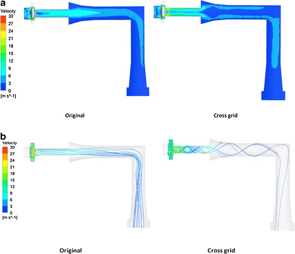
Contour of velocity (a) and streamline (b) of air flow in the original and cross-grid Aerolizers with the USP induction port at 60 L/min
DISCUSSION
The mouthpiece length was shown to have no significant effect on the aerosolization of carrier-based DPI formulations by the Aerolizer device. This was consistent with the CFD data which showed identical flow patterns and turbulence generated in the inhaler device when the mouthpiece length was reduced. These findings are in good agreement with the previous report (5).
Reduction in the air inlet size of the Aerolizer increases the air velocity in the inhaler base and the overall turbulence levels (Fig. 6). The velocity had an increase of 67% from 14.1 to 23.5 m/s and the turbulence kinetic energy increased 297% from 6.0 to 23.8 J/kg at the flow rate of 60 L/min when the air inlet size was reduced to 1/3 of the original (6). The pressure drop across the device also increased with a reduction in air inlet size (Table I). Such increases in the air velocity, device resistance, and overall turbulence contribute to the enhanced detachment of drug particles from the carrier surface and to the improvements in drug aerosolization. In the previous study on the drug-only mannitol powder, the aerosolization efficiency was decreased after reducing the inlet size at the flow rates >60 L/min (6). This was due to the premature emptying of a significant portion of the powder from the capsule before the turbulence level was fully developed in the swirling chamber of the inhaler. The result that this effect was not important in the present study suggested that the dispersion mechanism of the carrier-based system (where drug particles are detached from the carrier surfaces due to sliding and/or rolling as compared with the drug-only mannitol system where powder agglomerates break up into smaller fragments and primary drug particles) is less sensitive to the timing of turbulence flow development in the Aerolizer. The difference may depend on the inter-particulate forces in the drug-carrier powders and their interaction with the turbulence and impaction inside the inhaler. This will warrant a systemic investigation in the future to provide an in-depth understanding of the observed effect.
Table I.
Volume Averaged Air Velocity and Pressure Drop Data for the Original and 1/3 Inlet Size Devices at Different Flow Rates
| Original device | 1/3 Inlet size device | |||||
|---|---|---|---|---|---|---|
| 30 L/min | 60 L/min | 100 L/min | 30 L/min | 60 L/min | 100 L/min | |
| Air velocity (m/s) | 6.9 | 14.1 | 24.1 | 11.5 | 23.5 | 39.5 |
| Pressure drop (kPa) | 0.3 | 1.0 | 3.5 | 1.0 | 4.2 | 12.0 |
Device resistance is an important characteristic of an inhaler device which determines how easily a patient can generate a certain air flow (20). However, an inhaler with a higher resistance does not necessarily provide more efficient aerosolization (21). In the present study, air velocity and overall turbulence were found to be more important than pressure drop for the aerosolization of a carrier-based DPI. For example, the original device at 100 L/min produced a device pressure drop of 3.5 kPa, which was lower than the value for the 1/3 inlet device at 60 L/min (4.2 Pa). However, their linear air velocity values (23.5 m/s for the 1/3 inlet at 60 L/min and 24.1 m/s for the original at 100 L/min) and turbulence kinetic energy (23.8 J/kg for the 1/3 inlet at 60 L/min and 22.4 J/kg for the original at 100 L/min) were almost identical. Importantly, there were no significant differences in the FPF total and FPF emitted between the original device at 100 L/min and the 1/3 inlet device at 60 L/min. Furthermore, the 1/3 inlet device at 30 L/min had an identical pressure drop of 1.0 Pa to that of the original device at 60 L/min while both the air velocity and turbulence kinetic energy were lower. Yet, the FPF total of the 1/3 inlet device at 30 L/min was significantly lower than that the original device at 60 L/min (p < 0.01). This confirms air velocity and turbulence kinetic energy being more critical than device pressure drop for drug particle detachment from carrier surfaces. It is worth of noting certain patients like the elderly or children may not be able to generate a high flow through a high-resistance device during inhalation. If a higher flow rate through the 1/3 inlet device can be generated by the patients, the drug delivery efficiency can be improved.
Increasing the voidage of the grid (cross-grid device) will result in a more swirling flow in the mouthpiece and induction port with the air velocity near mouthpiece and induction port walls being increased and higher than that in the middle of the air tunnel (Fig. 7). This will enhance the interactions between the particles and the inhaler mouthpiece and induction port walls, causing more drugs to deposit on the mouthpiece and induction port. In a previous study using mannitol as pure drug without carrier, the cross-grid device caused a reduction in FPF total (5). Yet this did not cause significant changes in the FPF total and FPF emitted here for a carrier-based system. From the in vitro deposition data, it can be calculated that 18% more drugs were deposited in the mouthpiece and induction port of the cross-grid device compared with the original device at 60 L/min. On the other hand, 16.1% less drugs were deposited on stages 1 and 2. Similar results can be also obtained at flow rates of 30 and 100 L/min. We postulate that the drug particles escaped the deposition from the mouthpiece and induction port of the original device deposited on stages 1 and 2 instead, together with the lactose carriers. To confirm this hypothesis, the deposition of lactose carrier on each stage of the liquid impinger was also measured. Figure 8 showed that 25.9% more lactose particles were deposited in the induction port for the cross-grid device while 25.3% more lactose particles were deposited on stages 1 and 2 for the original device. Similar to the drug deposition, these data demonstrated that using the original device the lactose escaped deposition from the induction port and deposited on the stages 1 and 2 instead. Both the drug and the lactose have a similar deposition pattern suggesting the drug particles may be attached to the lactose carriers after having exited from the swirling chamber of the inhaler. Thus, detachment of the drug particles from the carrier surface mainly occurs inside the inhaler chamber and/or through the grid prior to entering the mouthpiece and induction port.
Fig. 8.
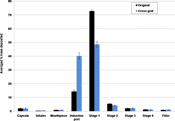
Deposition of lactose on each stage of the multi-stage impinger at 60 L/min (n = 3)
It is interesting to note the difference in the influence of the grid design on the deposition of particles between the drug-only and carrier-based DPI systems. For the carrier-based system in this study, 18% more drug particles were deposited in the induction port for the cross-grid device than the original device. The difference of drug deposition in the mouthpiece between the two devices is only 2.2%. In contrast, for the drug-only system of mannitol, there was no difference found in drug deposition in the induction port but a marked difference was observed in the mouthpiece between the two devices (5). It is not surprising that micronized drug particles like mannitol are adhesive and tend to stick to the inhaler surface during the swirling air stream in the mouthpiece of the cross-grid device. However, for the lactose carrier with a much larger particle size (median particle size ≈54 μm in this study), they may not easily adhere on the mouthpiece due to a larger mass hence a higher momentum which enables most of the lactose particles to bounce off from the surface during impact. When the air stream enters the induction port, the velocity decreases but the swirling air stream pattern remains (Fig. 7). Such air flow with the reduced velocity has less ability to carry the lactose carrier particles off the induction port surface during the interaction hence more lactose particles were deposited in the induction port.
To elucidate the carrier particle deposition behavior during the aerosolization, the dynamics of powders were investigated from the simulations. Figure 9 showed the carrier–wall impactions mostly occurred inside the chamber for both the cross-grid and original devices. The impaction velocity was generally higher inside the inhaler chamber than in the mouthpiece and induction port. This confirms the detachment between drug and carrier particles may mainly occur inside the chamber. Also, the cross-grid design increased the impaction loss on both mouthpiece and induction port. Since the impaction velocity in the induction port was shown much lower than that in the mouthpiece, more lactose particles deposited in induction port instead of bouncing off the walls (Fig. 9).
Fig. 9.
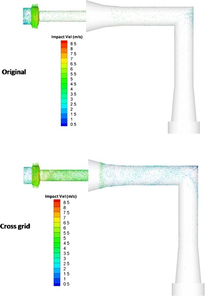
Spatial distribution of total carrier particle–wall collision in the inhaler and USP induction port (colors represent impaction velocity between particles and wall) of the original device and cross-grid device
For the Aerolizer device, the powder contained in the capsule needs to be released through the pierced holes at each end of the capsule during the aerosolization. The centrifugal force generated by the spinning capsule will eject the powder through the capsule holes. When the air flow increases, the capsule rotation speed will increase from 1,350 rpm at 30 L/min to 2,700 rpm at 60 L/min (19), which increases the centrifugal force hence facilitates the powder exit. Capsule retention has impact on the FPF total and more importantly, affects the delivered dose to the patients. The FPF total and FPF emitted values are higher when the air flow rate was increased for all four devices examined in this study (p < 0.05). The air velocity was increased from 6.9 to 14.1 m/s and turbulence kinetic energy increased from 0.81 to 6.0 J/kg when the air flow rate was increased from 30 to 60 L/min for the original device (19). At a lower flow rate of 30 L/min, greater variations in drug retained in the capsules were shown for all devices compared to the higher flow rates (Fig. 4). For example, the coefficient of variation increased from 0.059 at 100 L/min to 0.395 at 30 L/min for the original device. Such effect of air flow rate on the device emptying can be more significant for cohesive, non-free flowing powders (22).
CONCLUSIONS
The mouthpiece length was demonstrated to exert no significant effect on the aerosolization of Foradile from the Aerolizer. The simulation results confirmed that there was no noticeable difference in the air flow patterns in the inhaler when the mouthpiece length was reduced. Improved aerosol performance was shown after the inlet size of the device was reduced. These improvements were attributed to the increases in the air velocity and turbulence level. The cross-grid device had more drug deposition in induction port due to the swirling air flow pattern in mouthpiece extending into the induction port, which was explained due to the lower impaction velocity in induction port by CFD-DEM analysis. However, there were no significant differences in the FPF between the original and the cross-grid devices indicating the detachment of the drug particles from carriers occurs mainly inside the inhaler chamber before they enter the mouthpiece and induction port. The CFD-DEM analysis also confirmed most high-velocity particle–wall impactions occurred in the inhaler chamber. This study identifies critical design features of the Aerolizer device which would affect the aerosolization of carrier-based dry powders.
ACKNOWLEDGMENTS
The authors acknowledge the facilities, and the scientific and technical assistance, of the Australian Microscopy & Microanalysis Research Facility at the Australian Centre for Microscopy and Microanalysis, The University of Sydney. The study was financially supported by the Australian Research Council (grant DP110105161). Qi (Tony) Zhou is an Australian National Health and Medical Research Council (NHMRC) Early Career Fellow.
REFERENCES
- 1.Chan HK. Dry powder aerosol delivery systems: current and future research directions. J Aerosol Med Depos Clearance Eff Lung. 2006;19(1):21–27. doi: 10.1089/jam.2006.19.21. [DOI] [PubMed] [Google Scholar]
- 2.Zhou Q, Morton DAV. Drug–lactose binding aspects in adhesive mixtures: controlling performance in dry powder inhaler formulations by altering lactose carrier surfaces. Adv Drug Deliv Rev. 2012;64(3):275–284. doi: 10.1016/j.addr.2011.07.002. [DOI] [PubMed] [Google Scholar]
- 3.De Boer AH, Chan HK, Price R. A critical view on lactose-based drug formulation and device studies for dry powder inhalation: which are relevant and what interactions to expect? Adv Drug Deliv Rev. 2012;64(3):257–274. doi: 10.1016/j.addr.2011.04.004. [DOI] [PubMed] [Google Scholar]
- 4.Voss A, Finlay WH. Deagglomeration of dry powder pharmaceutical aerosols. Int J Pharm. 2002;248(1–2):39–50. doi: 10.1016/S0378-5173(02)00319-8. [DOI] [PubMed] [Google Scholar]
- 5.Coates MS, Fletcher DF, Chan HK, Raper JA. Effect of design on the performance of a dry powder inhaler using computational fluid dynamics. Part 1: grid structure and mouthpiece length. J Pharm Sci. 2004;93(11):2863–2876. doi: 10.1002/jps.20201. [DOI] [PubMed] [Google Scholar]
- 6.Coates MS, Chan HK, Fletcher DF, Raper JA. Effect of design on the performance of a dry powder inhaler using computational fluid dynamics. Part 2: air inlet size. J Pharm Sci. 2006;95(6):1382–1392. doi: 10.1002/jps.20603. [DOI] [PubMed] [Google Scholar]
- 7.Coates MS, Chan HK, Fletcher DF, Chiou H. Influence of mouthpiece geometry on the aerosol delivery performance of a dry powder inhaler. Pharm Res. 2007;24(8):1450–1456. doi: 10.1007/s11095-007-9262-z. [DOI] [PubMed] [Google Scholar]
- 8.Donovan MJ, Kim SH, Raman V, Smyth HD. Dry powder inhaler device influence on carrier particle performance. J Pharm Sci. 2012;101(3):1097–1107. doi: 10.1002/jps.22824. [DOI] [PubMed] [Google Scholar]
- 9.Shur J, Lee S, Adams W, Lionberger R, Tibbatts J, Price R. Effect of device design on the in vitro performance and comparability for capsule-based dry powder inhalers. AAPS J. 2012;14(4):667–676. [DOI] [PMC free article] [PubMed]
- 10.Tong ZB, Zheng B, Yang RY, Yu AB, Chan HK (2012). CFD-DEM investigation of the dispersion mechanisms in commercial dry powder inhalers. Powder Technol. 2012. doi:10.1016/j.powtec.2012.07.012.
- 11.Young PM, Roberts D, Chiou H, Rae W, Chan HK, Traini D. Composite carriers improve the aerosolisation efficiency of drugs for respiratory delivery. J Aerosol Sci. 2008;39(1):82–93. doi: 10.1016/j.jaerosci.2007.10.003. [DOI] [Google Scholar]
- 12.Asking L, Olsson B. Calibration at different flow rates of a multistage liquid impinger. Aerosol Sci Technol. 1997;27(1):39–49. doi: 10.1080/02786829708965456. [DOI] [Google Scholar]
- 13.Chew NYK, Chan HK. In vitro aerosol performance and dose uniformity between the Foradile (R) Aerolizer (R) and the Oxis (R) Turbuhaler (R) J Aerosol Med Depos Clearance Eff Lung. 2001;14(4):495–501. doi: 10.1089/08942680152744703. [DOI] [PubMed] [Google Scholar]
- 14.Kumon M, Kwok PCL, Adi H, Heng D, Chan HK. Can low-dose combination products for inhalation be formulated in single crystalline particles? Eur J Pharm Sci. 2010;40(1):16–24. doi: 10.1016/j.ejps.2010.02.004. [DOI] [PubMed] [Google Scholar]
- 15.Zhu HP, Zhou ZY, Yang RY, Yu AB. Discrete particle simulation of particulate systems: theoretical developments. Chem Eng Sci. 2007;62(13):3378–3396. doi: 10.1016/j.ces.2006.12.089. [DOI] [Google Scholar]
- 16.Wang B, Xu DL, Chu KW, Yu AB. Numerical study of gas–solid flow in a cyclone separator. Appl Math Model. 2006;30(11):1326–1342. doi: 10.1016/j.apm.2006.03.011. [DOI] [Google Scholar]
- 17.Launder BE, Reece GJ, Rodi W. Progress in development of a Reynolds-stress turbulence closure. J Fluid Mech. 1975;68:537–566. doi: 10.1017/S0022112075001814. [DOI] [Google Scholar]
- 18.Chu KW, Wang B, Yu AB, Vince A. CFD-DEM modelling of multiphase flow in dense medium cyclones. Powder Technol. 2009;193(3):235–247. doi: 10.1016/j.powtec.2009.03.015. [DOI] [Google Scholar]
- 19.Coates MS, Chan HK, Fletcher DF, Raper JA. Influence of air flow on the performance of a dry powder inhaler using computational and experimental analyses. Pharm Res. 2005;22(9):1445–1453. doi: 10.1007/s11095-005-6155-x. [DOI] [PubMed] [Google Scholar]
- 20.Clark AR, Hollingworth AM. The relationship between powder inhaler resistance and peak inspiratory conditions in healthy volunteers—implications for In vitro testing. J Aerosol Med Depos Clearance Eff Lung. 1993;6(2):99–110. doi: 10.1089/jam.1993.6.99. [DOI] [PubMed] [Google Scholar]
- 21.Srichana T, Martin GP, Marriott C. Dry powder inhalers: the influence of device resistance and powder formulation on drug and lactose deposition in vitro. Eur J Pharm Sci. 1998;7(1):73–80. doi: 10.1016/S0928-0987(98)00008-6. [DOI] [PubMed] [Google Scholar]
- 22.Zhou QT, Armstrong B, Larson I, Stewart PJ, Morton DAV. Understanding the influence of powder flowability, fluidization and de-agglomeration characteristics on the aerosolization of pharmaceutical model powders. Eur J Pharm Sci. 2010;40(5):412–421. doi: 10.1016/j.ejps.2010.04.012. [DOI] [PubMed] [Google Scholar]


