Abstract
Purpose.
We characterized electrically elicited visual evoked potentials (eVEPs) in Argus II retinal implant wearers.
Methods.
eVEPs were recorded in four subjects, and analyzed by determining amplitude and latency of the first two positive peaks (P1 and P2). Subjects provided subjective feedback by rating the brightness and size of the phosphenes. We established eVEP input–output relationships, eVEP variability between and within subjects, the effect of stimulating different areas of the retina, and the maximal pulse rate to record eVEPs reliably.
Results.
eVEP waveforms had low signal-to-noise ratios, requiring long recording times and substantial signal processing. Waveforms varied between subjects, but showed good reproducibility and consistent parameter dependence within subjects. P2 amplitude overall was the most robust outcome measure and proved an accurate indicator of subjective threshold. Peak latencies showed small within-subject variability, yet their correlation with stimulus level and subjective rating were more variable than that of peak amplitudes. Pulse rates of up to 2/3 Hz resulted in reliable eVEP recordings. Perceived phosphene brightness declined over time, as reflected in P1 amplitude, but not in P2 amplitude or peak latencies. Stimulating-electrode location significantly affected P1 and P2 amplitude and latency, but not subjective percepts.
Conclusions.
While recording times and signal processing are more demanding than for standard visually evoked potential (VEP) recordings, the eVEP has proven to be a reliable tool to verify retinal implant functionality. eVEPs correlated with various stimulus parameters and with perceptual ratings. In view of these findings, eVEPs may become an important tool in functional investigations of retinal prostheses. (ClinicalTrials.gov number NCT00407602.)
Keywords: retinal implant, visual evoked potential, visual prosthesis, psychophysics
We characterized electrically elicited visual evoked potentials (eVEPs) in Argus II retinal implant wearers. eVEPs were correlated significantly with stimulus level and subjective percept. We conclude that eVEPs may become an important tool for intraoperative monitoring and rehabilitation purposes.
Introduction
The Argus II retinal prosthesis at present is the only visual prosthesis approved for commercial use; it received the CE Mark for use in Europe in 2011, and received FDA approval in 2013 in the United States. It is an epiretinal implant that stimulates the surviving neurons in the retina by means of an array of 6 × 10 electrodes.1 The Argus II has been proven to improve visual performance in spatial motor,1 and orientation and mobility tasks2 in implanted subjects with end-stage retinitis pigmentosa.
Although subjective measures are critical to assess retinal implant functionality, objective measures of prosthetic vision also are essential. In cochlear implants, which have been approved clinically since 1984,3 built-in electronics and reverse telemetry have been developed to allow recording of auditory nerve responses to electric stimuli. These measures nowadays are used routinely to assess functionality of the implant intraoperatively,4 and can be applied for rehabilitation purposes.5 Measurement of electrically evoked responses in the visual system likewise may prove useful during surgery and rehabilitation. The visual equivalent of the auditory nerve response is the electrically elicited electroretinogram (eERG). However, reverse telemetry is not yet available in the Argus II system, complicating eERG recordings. Cortical responses recorded from the scalp, for example, electrically elicited visual evoked potentials (eVEPs), are, therefore, a promising alternative. An additional advantage of cortical over peripheral potentials is the fact that the former represent central nervous system activity (V1 in case of eVEPs) and may provide a more accurate indication of perception. However, in contrast to the eERG, eVEPs do not provide detailed information about retinal processing, such as which cell populations are being activated, or whether any synaptic transmission is involved. Despite this important limitation, quantitative analysis of the eVEP may provide useful insights regarding processing of electrical stimuli by the visual system following retinal degeneration.
eVEPs have been well documented in animal models of retinal,6–14 optic nerve,15–17 and cortical implants.18 Most of these reports were feasibility studies and made use of normally sighted animals, which may not be representative for human visual prosthesis users. A limited number of reports describe eVEPs in animal models of retinal degeneration,19–22 while to our knowledge only three reports exist that describe eVEPs obtained in humans with retinal degeneration. Two of these reports show eVEP waveforms obtained in Argus I subjects.22,23 Brelen et al. show eVEP waveforms from two subjects with an optic nerve implant and found the promising result that the eVEP threshold reflected perceptual threshold.24 However, all of these studies are based mainly on sample waveforms, and not on a systematic quantitative study of the responses.
For eVEPs to gain clinical acceptance it is essential to characterize eVEP input–output characteristics quantitatively, establish the correlation between eVEPs and subjective percepts, determine the variability of eVEP recordings between and within subjects, and determine procedures to obtain the eVEP quickly and reliably. In our study we aimed to achieve these goals by characterizing eVEP responses in four Argus II–implanted subjects.
Materials and Methods
Subjects
Four subjects implanted with an Argus II retinal prosthesis in the right eye participated in this study. They were enrolled in an ongoing safety/efficacy study sponsored by Second Sight Medical Products (SSMP, Sylmar, CA; available in the public domain at http://clinicaltrials.gov/ct2/show/NCT00407602). All subjects had been diagnosed with end-stage retinitis pigmentosa, and had no residual visual function greater than bare-light perception. Three subjects had been implanted approximately 4.5 years before the experiment was initiated (subjects S2, S3, and S4), while one subject had the implant for 2.5 years (S5).
All experiments adhered to the tenets of the Declaration of Helsinki. Informed consent was obtained from each subject after explanation of the nature and possible consequences of evoked electrical response recording. This research was approved by the institutional review board of the Johns Hopkins Hospital.
Experimental Setup
eVEPs were measured using the Espion e2 system (Diagnosys LLC, Westford, MA) operating at the maximum sampling rate of 5 kHz, with open filter settings (0–1000 Hz setting). The electrical stimulus artifact was used as an external trigger to start recording. A typical run consisted of 250 stimuli delivered at 1/3 Hz (totaling 12.5 minutes recording time). Typically, 6 runs were performed in a single session. After each run, a short break (typically 2–4 minutes) was provided.
Recording was performed using gold cup electrodes (Grass Technologies, West Warwick, RI) placed on the scalp with conductive paste (Ten20; Weaver and Company, Aurora, CO). The active electrode was placed midline on V1, 1 cm above the inion, the reference was placed on the forehead, and the ground electrode was placed on the right wrist.
eVEPs were elicited with the prosthesis operating under direct computer control, rather than with camera input. To ensure maximal cortical responses, electrodes were stimulated synchronously, and typically all available electrodes were stimulated. The stimulation software we used set the same current amplitude for each electrode. Therefore, electrodes with lower thresholds could have conveyed brighter percepts, and the subjective threshold may have been determined mainly by those electrodes with low stimulus thresholds.
Stimuli consisted of biphasic, rectangular current pulses. Default stimulation parameter settings were as follows: Cathodic-phase first pulses, 450 μs/phase, no interphase gap (IPG = 0), pulse rate 1/3 Hz, and a stimulus level of approximately 2 times subjective threshold (as determined under default conditions). Effects of stimulus level (10–58 μA per electrode, dependent on the subject), stimulus polarity (cathodic- versus anodic-first stimuli), IPG (0 or 1 ms), and pulse rate (1/6 to 2 Hz) were varied systematically, leaving all other parameters at default. Throughout each run all stimulus parameters were kept constant.
Because we stimulated all electrodes synchronously, the maximum possible current level was restricted by the implant electronics and depended on the number of available electrodes. S2 had 51 active electrodes, and the current limit was 58 μA when all electrodes were stimulated synchronously. S3 and S5 had 55 and 56 active electrodes, respectively, and a the current limit was 54 μA. S4 had 33 electrodes available, but was not tested for current-level dependence due to time restrictions; only a sample waveform at moderate stimulus level was obtained. Given the electrode area of 0.03 mm2 and typical pulse duration of 0.46 ms, the charge density at the highest tested current level was 0.08 mC/cm2; approximately an order of magnitude below the safe charge density limit of 1 mC/cm2 for a Pt-Ir electrode surface, as defined in the safety regulations in the FDA-approved study protocol.
During each run, subjects were asked four times at regularly spaced intervals to provide subjective feedback by rating the brightness and size of the most recent phosphene (typically at 3, 6, 9, and 12 minutes). Ratings were confined to integers from 0 to 10; “0” indicating “no percept” and “10” being the “brightest/largest phosphene they had ever seen.” Since eVEP amplitude is expected to depend on the product of the firing rate of V1 neurons (reflected by phosphene brightness), and the number of active neurons (phosphene size), brightness and size were multiplied and rescaled back to 0 to 10 by taking the square root of the product. The four ratings usually were averaged to obtain a whole-run rating.
Data Analysis
eVEP data were imported in a Matlab R2010a programming environment (Natick, MA). Data were contaminated by background noise, signal drift, movement artifacts, and electric stimulus artifacts. To reduce background noise, a level 6 stationary wavelet transformation (SWT)25–28 was performed using the “sym5” wavelet. After SWT the data had a spectral content, based on fast-Fourier transform analysis, similar to that when low-pass filtering the signal with a digital sixth order Butterworth filter with a cutoff-frequency of 50 Hz. The reason for using SWT was a superior reduction of stimulus artifacts.
Based on previous literature,24 the first 400 ms of each epoch was analyzed. After SWT, the linear slope and mean value of each epoch were set to zero to eliminate signal drift. Noise was reduced by adaptive averaging of multiple epochs: First, only epochs with overall amplitude < 50 μV were included. The amplitude limit for inclusion then was increased until at least 50% of epochs were accepted. If this procedure resulted in an insufficient signal-to-noise ratio (SNR) upon visual inspection, additional 250-epoch runs were performed in a next session. For S5, single 250-epoch runs were sufficient, while for the other subjects up to 5 runs had to be combined.
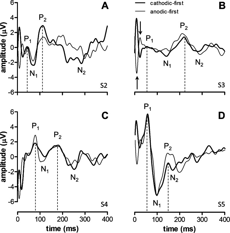
Averaged eVEPs were analyzed by visually determining positive and negative peaks. For peak designation we followed the ISCEV standard for flash VEPs. eVEPs are plotted with positive peaks up following earlier publications.22–24 eVEPs were characterized using the first two identifiable positive peaks (P1, P2) and the first negative peak (N1). Amplitudes of the positive peaks were determined relative to N1 (Fig. 1), and latencies relative to stimulus onset (t = 0 ms).
Figure 1. .
eVEP waveforms obtained at a stimulus level approximately 2 times subjective threshold at standard parameter settings (thick lines). eVEPs using anodic-first stimuli (thin lines) also are shown to illustrate the stimulus-polarity–dependent artifact at approximately 25 ms (shown for subject S3 in [B], arrows). eVEP waveforms were characterized by two positive peaks (P1 and P2) and two negative peaks (N1 and N2). N1 and P2 were robust peaks across subjects, and the most reliable eVEP amplitude was obtained using P2 relative to N1. P1 was robust in S5 only. P1 amplitudes were also determined relative to N1. eVEP amplitudes and latencies for these waveforms are provided in Table 1.
Estimation of eVEP threshold was done by fitting the input–output relation with a straight line. The eVEP threshold response level was defined as 4·SD (i.e., the 99% confidence interval [CI99]) of the mean waveform obtained just below perceptual threshold. The stimulus level at the intersection of the fitted curve and the horizontal line y = 4·SD yielded the eVEP threshold.
Statistical analyses were done with Prism 5.04 (GraphPad Software, San Diego, CA), and included correlation analyses using linear regression and F-tests on the slope (H0: slope = 0; i.e., a horizontal line), 2-tailed t-tests (paired or unpaired), and 1-way RM ANOVA. Effects were tested within subjects where possible. Significance level α was always 0.05.
Results
: eVEP Waveforms
Figure 1 shows sample eVEP waveforms obtained under default parameter settings. eVEPs were characterized by two positive peaks (P1 and P2) and a negative peak (N1). We also identified an early component around 25 ms that most likely represented a polarity-dependent stimulus artifact (see Discussion). The electrical stimulus artifact itself occurred between 0 and 1 ms (pulse width = 900 μs), and was removed effectively by SWT.
Table 1 shows that P1 amplitude (P1 amp.) varied by an order of a magnitude, while P2 amplitude (P2 amp.) was comparable between subjects. P1 and P2 latency (P1 and P2 lat.) varied by a factor 2 between subjects. Table 1 also shows subjective electrical threshold (Thresh.), mean impedance across all electrodes (Imped.), mean impedance in the macular region (Imped. macula), and residual light perception (FST) of the subjects.
Table 1. .
Subjects Overview
|
|
Thresh., mC |
Imped., kΩ |
Imped. Macula, kΩ |
FST, dB |
P1 Lat., ms |
N1 Lat., ms |
P2 Lat., ms |
P1 Ampl., μV |
P2 Ampl., μV |
| S2 | 0.7 | 14 | 17 | +18 | 40 | 60 | 120 | 3 | 5 |
| S3 | 0.4 | 7 | 6 | −12 | 50 | 140 | 220 | 1 | 3 |
| S4 | 0.4 | 19 | 16 | +24 | 80 | 120 | 180 | 2 | 2 |
| S5 | 0.3 | 13 | 13 | +7 | 60 | 100 | 150 | 11 | 4 |
Implant parameters, residual light sensitivity, and eVEP characteristics per subject. The subjective electrical threshold (Thresh.) was determined by stimulating all electrodes at the same current level, and is expressed as the applied total charge to correct for the number of functional electrodes. Impedance is expressed as the mean across all individual functional electrodes (Imped.), and across those electrodes covering the macula (max. 4) based on fundus photos (Imped. macula). Residual light sensitivity was assessed by a standard flash test (Diagnosys full-field scotopic stimulus threshold [FST], 0 dB level: 3 Cd·s·m−2). eVEP peak (P1 and P2) latencies (lat.) and amplitudes (ampl.) were obtained at approximately 2 times subjective threshold (waveforms shown in Fig. 1).
Effects of Stimulus Level
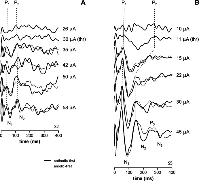
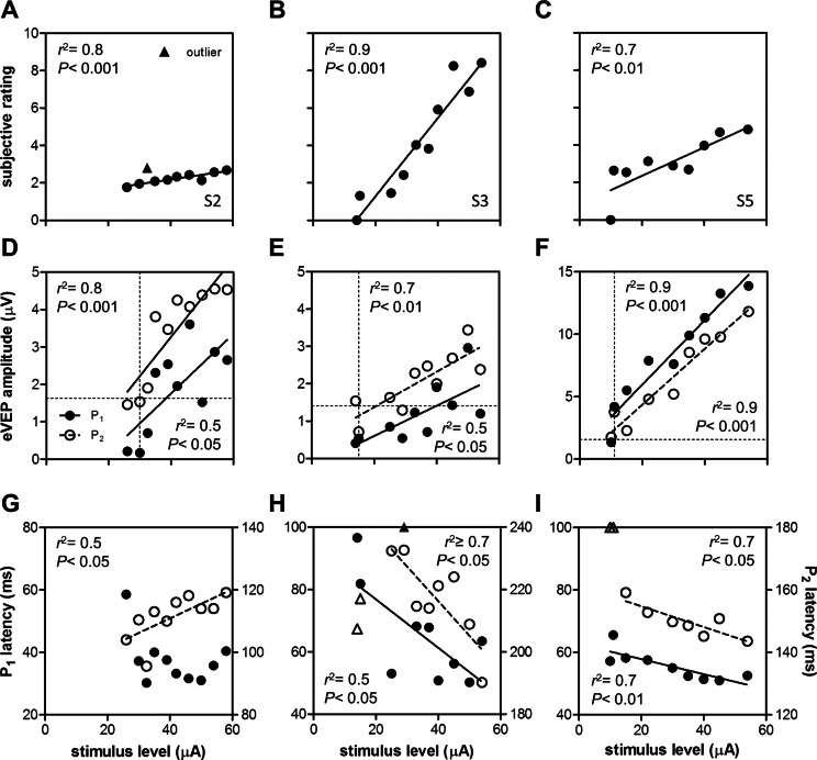
In three subjects we obtained eVEP waveforms at stimulus levels from below subjective threshold up to the maximum safe current level (Fig. 2). All subjects showed a significant increase in subjective rating, and P1 and P2 amplitudes with stimulus level (Figs. 3A–F, linear regression and F-tests, P < 0.05). P1 and P2 latencies decreased significantly with stimulus level in S3 and S5 (Figs. 3G–I, P < 0.05). In S5, P2 was hardly visible at 11 and 15 μA (Fig. 2B), and these data were disregarded (Fig. 3I). In S2, P1 latency did not depend significantly on stimulus level, while P2 latency unexpectedly increased with stimulus level (Fig. 3G).
Figure 2. .
Sample eVEP waveforms in 2 subjects S2 (A) and S5 (B) at various current levels. Recordings were performed at standard settings (thick lines). Where available, waveforms using anodic-first stimuli also are shown to illustrate stimulus artifact-related peaks (thin lines). Applied current levels and subjective threshold (thr) are indicated.
Figure 3. .
Effects of stimulus level on subjective rating (A–C), eVEP amplitude (D–F), and eVEP latency (G–I). Data were fitted by linear regression. Correlation coefficient (r2), and P values based on F-tests (H0: slope = 0) are indicated (insets). If the fitted function was not significantly different from the no-effect level, no line was drawn ([G], P1 data). eVEP data are shown for P1 (solid symbols) and P2 (open symbols). Outliers are indicated with triangles (A, H, I). When outliers were outside the y-axis limits, they are drawn at the highest level available (H, I). eVEP threshold amplitudes (D–F) were determined by calculating the x-intercept of the fitted function with the threshold amplitude y = 4·SD (horizontal dashed line, see Materials and Methods). These P1 and P2 threshold stimulus levels were compared with the subjective threshold (vertical dashed line).
To examine whether eVEP amplitude and latency reflected subjective percept, we correlated P1 and P2 amplitudes and latencies (Figs. 3D–I) with subjective ratings (Figs. 3A–C) using linear regression. For all subjects, P1 and P2 amplitudes increased significantly with rating (F-test, P < 0.05). Effects on latency were more variable: For S2, P1 latency was not correlated significantly with rating (P = 0.1), while P2 latency increased with rating (P < 0.05). For S3, there was a trend for P1 and P2 latency to decrease with rating (P = 0.07 in both cases), while in S5, P1 and P2 latency decreased significantly with rating (P < 0.05). N1 latency showed a nonmonotonic dependence on stimulus level and rating in all subjects, and was not statistically analyzed.
We determined eVEP P1 and P2 thresholds by determining the stimulus amplitude at which the regression amplitude data dropped to the 4·SD level (horizontal dashed line in Figs. 3D–F). P2 threshold approximated the subjective threshold better than P1 threshold in all subjects (Table 2).
Table 2. .
Subjective and Electrophysiological Threshold Levels, by Subject
|
Subject |
Subjective Threshold, μA |
eVEP Threshold, μA |
|
|
P1 |
P2 |
||
| S2 | 30 | 38 | 24 |
| S3 | 15 | 40 | 21 |
| S5 | 11 | 3 | 7 |
Subjective thresholds and interpolated eVEP thresholds obtained from the fitted eVEP input–output (IO) characteristics based on P1 and P2 amplitudes.
Effects of Stimulus Waveform
We recorded eVEPs using cathodic-first and anodic-first stimuli at various current levels in three subjects (for sample waveforms see Figs. 1 and 2). We had only a limited number of data points per subject and, therefore, the data were pooled, resulting in 11 anodic-first–cathodic-first stimulus pairs (S2, n = 4; S3, n = 3; S5, n = 4). To account for between-subject differences in absolute values, we normalized the data per subject (highest latency, amplitude, or rating recorded was set to 1). Since P1 was robust only in S5 we analyzed P2. Subjective ratings were significantly larger using cathodic-first stimuli (mean difference 8%, 2-tailed t-test, P < 0.01), but no significant differences in either P2 latency or amplitude were observed (P > 0.05; data not shown).
Effects of interphase gap (IPG 0 or 1 ms) were tested in a similar fashion by pooling and normalizing data from 2 subjects (S3 and S5, 3 stimulus levels per subject). Subjective rating was significantly higher at IPG = 1 ms (Fig. 4B, mean difference 17%, P < 0.05), and P2 amplitudes were significantly larger (Fig. 4D, P < 0.01). No effect on P2 latency was found (P > 0.05).
Figure 4.
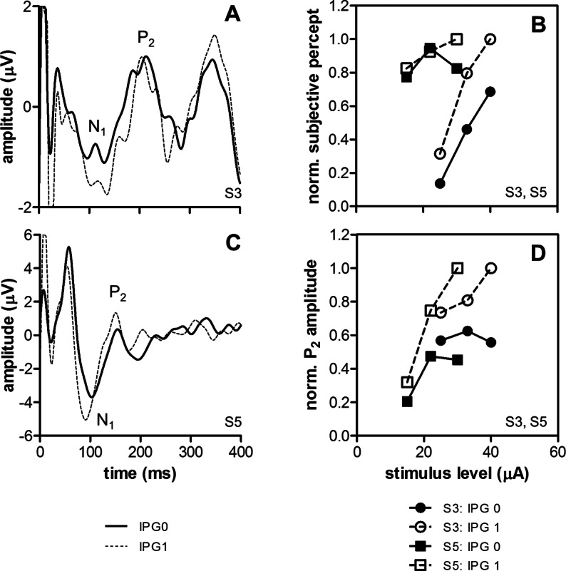
Effects of IPG in 2 subjects (S3 and S5). Sample eVEP waveforms are shown for S3 (A) and S5 (C) using pulses with IPG = 0 ms (thick lines) or IPG = 1 ms (dashed lines). Stimulus level was approximately 2 times subjective threshold. Normalized subjective ratings (B) and eVEP P2 amplitudes (D) were significantly larger at IPG = 1 ms (2-tailed, paired t-tests, P < 0.05).
Effects of Pulse Rate
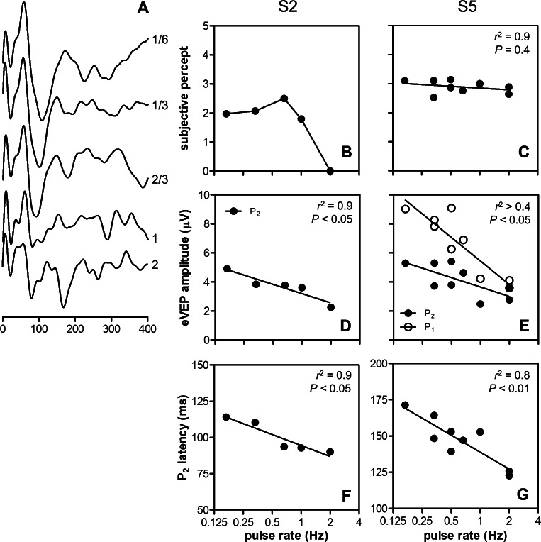
Pulse rate was varied in two subjects (S2 and S5). Pronounced effects on eVEP waveforms were observed (Fig. 5A), especially at rates of 1 Hz and above. S2 reported negligible subjective effects of pulse rate, except at 2 Hz, where only the first two (out of 250) stimuli were perceived (Fig. 5B). Pulse rate had no significant effect on subjective rating in S5 (Fig. 5C, linear regression, F-test, P = 0.4). Both subjects showed a significant reduction of eVEP amplitude with pulse rate (Figs. 5D, 5E; P < 0.05). P2 latencies decreased significantly with increasing stimulus rate in both subjects (Figs. 5F, 5G; P < 0.05). P1 latency was unaffected in S5 (P > 0.05; data not shown), and was not analyzed in S2 (P1 too small).
Figure 5. .
Effects of stimulus rate in 2 subjects (S2 and S5). Sample eVEP waveforms at various pulse rates are shown for S5 (A). Subjective ratings (B, C), eVEP amplitude (D, E), and eVEP latency (F, G) as a function of pulse rate are shown for both subjects. Dependence of these parameters on pulse rate was tested with linear regression. Correlation coefficients (r2) of the regression analysis and significance levels (P) based on F-tests on the slope are shown (insets).
Effects of Electrode Location
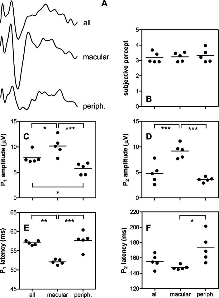
The effect of stimulating different sets of electrodes on eVEP waveforms (Fig. 6A) was tested in S5 using three conditions: stimulation of 3 × 3 electrodes overlaying the central macula based on fundus photos (C6–E8 on the electrode grid), stimulation of 9 peripheral electrodes (A1–B3, C1, C3, D1), and whole-array stimulation. The stimulus level was inversely proportional to the electrode number; when using 9 electrodes the current level was 56/9 times that when stimulating the whole grid with 56 active electrodes (i.e., 137 μA vs. 22 μA). Although subjective ratings did not differ significantly across the three conditions (Fig. 6B, RM ANOVA, P > 0.05), macular stimulation resulted consistently in higher P1 and P2 amplitudes, and shorter latencies compared to peripheral stimulation (Figs. 6C–F, P < 0.05). Comparing whole-array with macular stimulation, the latter resulted in larger P1 and P2 amplitudes, and shorter P1 latency (P < 0.05), but no effect on P2 latency was found (P > 0.05). Peripheral stimulation resulted in very similar responses compared to stimulation of the whole array, except that P1 amplitudes were significantly larger when stimulating all electrodes (P < 0.05).
Figure 6. .
Effects of electrode location in S5. Sample eVEP waveforms using the whole array (all), the central macular 9 (macular), or the most peripheral 9 electrodes (periph.) are shown (A). Stimulus level was 22 μA when stimulating the while grid (56 active electrodes), and 137 μA when stimulating 9 electrodes (proportionally corrected: 22 μA × 56/9). Effects of electrode location on subjective rating (B), eVEP P1, and P2 amplitude (C, D) and latency (E, F) were tested for statistical significance with RM ANOVA and Tukey's post hoc test. Mean values (lines) and significance levels are indicated. *P < 0.05. **P < 0.01. ***P < 0.001.
Within-Subject eVEP Variability
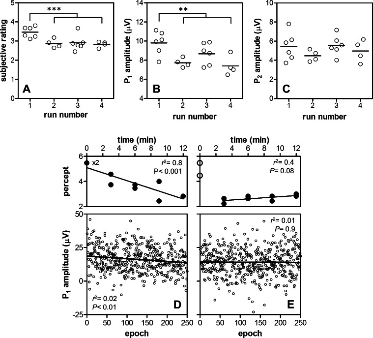
eVEP data of S5 were well suited for analysis of within-subject variability, since single runs of 250 stimuli resulted in sufficient SNRs. Figures 7A to 7C show the available data from S5 across multiple sessions under default parameter settings, grouped according to run number. Ratings in the first run were higher compared to later runs (Fig. 7A, unpaired, 2-tailed t-test, P < 0.001). Likewise, P1 amplitudes were significantly larger in the first run (Fig. 7B, P < 0.01). No significant effect of run number was found on P2 amplitude (Fig. 7C, P > 0.05), or P1 or P2 latency (P > 0.05; data not shown). Overall, latencies showed a relatively small variability compared to amplitude measures.
Figure 7. .
eVEP and perceptual variability. Subjective percept ratings (A) and eVEP P1 (B) and P2 (C) amplitudes from 20 runs across 11 sessions were pooled. A significant part of total subjective and P1 amplitude variability could be explained by between (A, B) and within (D, E) run variability. Subjective ratings and P1 amplitudes were significantly higher in the first run compared to later runs ([A, B], unpaired, 2-tailed t-test); both decreased significantly in the first run ([D], linear regression, and F-test on the slope), but not in the second (E) or later runs. Significance levels ([A–C], **P < 0.01, ***P < 0.001) and regression parameters ([D–E], correlation coefficient r2 and P based on F-tests on the slopes) are indicated.
In two sessions, four consecutive runs under identical, default settings were performed. In the first run, subjective ratings decreased significantly over time (Fig. 7D, linear regression and F-test, P < 0.001), while in later runs (runs 2–4) ratings did not change (shown for run 2 in Fig. 7E, P > 0.05). Individual eVEP amplitudes within each run were estimated from single epochs by determining P1, N1, and P2 within a 20 ms range around the peaks identified in the mean waveform. Therefore, latencies could not be analyzed, because these were capped artificially. P1 amplitudes decreased significantly over time in the first run (Fig. 7D, P < 0.01), but not in subsequent runs (shown for run 2 in Fig. 7E, P > 0.05). Correlation was weak (r2 ∼ 0.01) due to the low SNR of single waveforms. P2 amplitude did not show a significant effect (P > 0.05; data not shown) in any of the runs.
Discussion
: eVEP Waveforms
Peak latencies obtained at stimulus levels 2 times above subjective threshold differed between subjects; P1 ranged from 40 to 80 ms, N1 from 60 to 140 ms, and P2 from 120 to 220 ms (Table 1). Previous studies with Argus I subjects show the following eVEP peak latencies: N1, 23 to 25 ms; P1, 50 to 52 ms; N2, 110 to 120 ms; and P2, 220 to 240 ms.22,23 The N1 peak reported in these studies was identified by us as a stimulus artifact, because it reversed in polarity when using anodic-first stimuli (Figs. 1, 2). The other peak latencies correspond closely to ours (Table 1), as expected given the similarity between the Argus I and II devices. Their P1 and P2 amplitudes (relative to their N2) were approximately 10 μV. Our subjects generally had much smaller peak amplitudes (Table 1). However, VEP amplitudes are known to vary substantially between subjects, presumably due to differences in cortical layout, cranial thickness, and relative conductance levels29 and, therefore, are not regarded as reliable parameters for between-subject comparisons.30
Data from optic nerve–implanted subjects (stimulus levels up to two times subjective threshold) showed the following peaks: P1, 75 ms; N1, 200 ms; P2, 250 ms.24 Although their P1 latencies lie within our P1 range, their N1 and P2 are longer than ours, which was not expected, since the optic nerve is located more centrally. Phosphenes were perceived centrally in their experiments,24 as well as in our subjects (our subjects were implanted in the macular region) and, hence, similar optic nerve fibers will have been activated. However, latency differences may be related to the different nature of stimulation by optic nerve cuff electrodes; the percept of optic nerve stimulation is likely to be more diffuse than that of retinal stimulation,31 leading to more diffuse and, therefore possibly slower, cortical processing. In addition, while retinal neurons are not myelinated, the optic nerve is, and faster-conducting fibers (those with thicker myelin sheaths) are more likely to be activated,32 possibly resulting in altered cortical responses.
We were not able to find clear predictive factors between subjects that could explain differences in eVEP waveforms (Table 1). Low electrode impedances, low subjective thresholds, and high residual light sensitivity (suggesting better overall retinal condition) theoretically would be positive indicators for implant function, and were expected to result in high-amplitude eVEPs with low peak latencies. However, S5 had by far the largest P1 amplitude, but this light sensitivity was only moderate, and impedances and subjective threshold were similar to S3, who had a negligible P1. S2 had the largest P2 amplitude, but had moderate light sensitivity, moderately high impedances, and the highest threshold. Similarly, peak latencies did not seem to relate to these parameters.
eVEP Input–Output Characteristics
Increased stimulus levels resulted in increased eVEP amplitudes in all subjects, and decreased latencies in 2 of 3 subjects, which is in accordance with the characteristics of the normal light-evoked VEP.30 Amplitudes of evoked potentials in general increase with stimulus level due to recruitment of nerve cells and an increase in neuronal cell activity. Decreasing latencies at higher stimulus levels can be explained by assuming that neurons reach their activation thresholds quicker and/or fire more synchronously. However, S2 showed increasing peak latencies at higher stimulus levels. It generally is assumed that relatively short electrical pulses of low amplitude primarily activate retinal ganglion cells directly,33–36 while higher stimulus levels may lead to recruitment of presynaptic elements, such as bipolar cells and residual photoreceptors. This activation of presynaptic cells can lead to a secondary volley of activity in ganglion cells up to 10 to 40 ms after the initial stimulus,37,38 in turn leading to delayed cortical activation.22 Such a recruitment of presynaptic cells in S2 theoretically could have contributed to increased eVEP peak latencies in S2 at higher stimulus levels (Fig. 5). However, attempting to explain retinal processing based on eVEP waveforms is speculative, because retinal processes are obscured in the eVEP due to visual processing in the thalamus (LGN) and the cortex. In addition, the origins of the different VEP peaks are not well understood. Although P1 generally is attributed to V1 activity, the origins of P2 still are open to debate30 and may represent activity in extrastriate areas, but it might as well be evoked by secondary V1 activity due to feedback from higher cortical areas.
The fact that our stimulation levels stayed well below the safe limit for the Pt-Ir surface (see Introduction) is relevant, since we never reached a response plateau in our subjects, and the input–output curves could be fitted with a simple linear equation (Fig. 3).
Since the correlation of peak latencies with stimulus level was relatively variable across subjects, and because P2 threshold was a better predictor of subjective threshold than P1 (Table 2), we concluded that eVEP P2 amplitude is the most robust measure of stimulus level and subjective percept, at least in this limited number of subjects.
Effects of IPG
Introduction of an IPG resulted in increased subjective ratings and larger P2 amplitudes (Fig. 4). Although not significant at the eVEP level (but significant in our rating data), cathodic-first stimuli are slightly more effective than anodic-first stimuli in epiretinal implants,39 and the effect of IPG in our study can be explained by assuming that the cathodic phase of a cathodic-first biphasic pulse is excitatory, while the following anodic phase has the opposite effect. Increasing IPG may allow the excitatory response to develop more fully, before being suppressed by the anodic phase.40
eVEP Variability and Adaptation
P1 and P2 latency were robust measures across sessions, while amplitudes were more variable (Fig. 7). These findings are in line with the widely accepted idea that VEPs are analyzed more preferably in terms of latency than in amplitude.30,41 Nevertheless, in terms of defining input–output characteristics, we concluded that amplitudes are more robust than latency measures.
During the first run subjective percept was high, but declined over time. In subsequent runs, ratings were low and relatively constant (Fig. 7). Hence, our data indicated that within-session (between-run) differences can have substantial effects on the subjective percept. Perceptual “fading” was described recently by Pérez Fornos et al. in Argus II subjects.42 They report a decline in phosphene brightness within seconds after the start of stimulation, contrasting the fading we described in our subject, which progressed over a course of 12 minutes. The difference might be explained by different stimulation rates; they used 5 to 60 Hz, while we used 1/3 Hz.
In our data, fading was reflected in P1 amplitudes, but not in P2, indicating that the two peaks represent physiologically different processes.
Clinical Implications
We concluded that P2 amplitude is a robust measure of visual cortical processing in retinal electrical stimulation, because it could be applied effectively to construct input–output characteristics, it significantly correlated with subjective percept, and it yielded fairly accurate predictions of subjective threshold. IPG significantly affected P2 amplitude as well, but more subtle effects, such as that of stimulus polarity, were not reflected in the eVEP.
Each waveform required about 12 minutes of recording time (250 stimuli, 1/3 Hz). In addition, for S2, S3, and S4, multiple runs were needed to obtain eVEP waveforms of acceptable signal-to-noise ratio. In a clinical setting, recording times preferably would have to be reduced. We showed that eVEP waveforms could be recorded reliably at 2/3 Hz as well, effectively reducing recording time by half. If eVEPs are to be used for rehabilitation purposes, such as clinical device fitting, input–output characteristics might not need to be constructed with as many data points as in this study. Instead, based on our finding that P2 amplitude linearly depends on stimulus level and percept, input–output characteristics might be approximated with just a few data points.
Central macular stimulation resulted in significantly higher eVEP amplitudes and shorter latencies when compared to more peripheral stimulation, while there was no significant effect on subjective ratings (Fig. 6). In addition, electrode impedances cannot explain the difference either, because these were similar across all electrodes; for example, macular impedances closely resembled the mean impedance across all electrodes (Table 1). Increased amplitudes with macular stimulation can be explained, however, by the location of the cortical representation of the fovea close to the scalp, and by the relatively large area in V1 that is devoted to the central macula when compared to more eccentric retinal areas.30 Hence, electrode location must be taken into account when using eVEPs in a clinical setting.
Supplementary Material
Acknowledgments
The authors thank the subjects for all their time and dedication.
Supported by National Institutes of Health Grant R21EY019991.
Disclosure: H.C. Stronks, Second Sight Medical Products (F, C), P; M.P. Barry, Second Sight Medical Products (F); G. Dagnelie, Second Sight Medical Products (F, C), P
References
- 1. Ahuja AK, Dorn JD, Caspi A, et al. Blind subjects implanted with the Argus II retinal prosthesis are able to improve performance in a spatial-motor task. Br J Ophthalmol. 2011; 95: 539–543 [DOI] [PMC free article] [PubMed] [Google Scholar]
- 2. Humayun MS, Dorn JD, Da Cruz L, et al. Interim results from the International Trial of Second Sight's Visual Prosthesis. Ophthalmology. 2012; 119: 779–788 [DOI] [PMC free article] [PubMed] [Google Scholar]
- 3. Zeng FG. Auditory prostheses: past, present, and future. In: Zeng FG, Popper AN, Fay RR. eds Cochlear Implants Auditory Prostheses and Electric Hearing. New York, NY: Springer-Verlag; 2004. [Google Scholar]
- 4. Van Wermeskerken GK, Van Olphen AF, Van Zanten GA. A comparison of intra- versus post-operatively acquired electrically evoked compound action potentials. Int J Audiol. 2006; 45: 589–594 [DOI] [PubMed] [Google Scholar]
- 5. Smoorenburg GF, Willeboer C, Van Dijk JE. Speech perception in nucleus CI24M cochlear implant users with processor settings based on electrically evoked compound action potential thresholds. Audiol Neurootol. 2002; 7: 335–347 [DOI] [PubMed] [Google Scholar]
- 6. Shivdasani MN, Luu CD, Cicione R, et al. Evaluation of stimulus parameters and electrode geometry for an effective suprachoroidal retinal prosthesis. J Neural Eng. 2010; 7: 036008 [DOI] [PubMed] [Google Scholar]
- 7. Yamauchi Y, Franco LM, Jackson DJ, et al. Comparison of electrically evoked cortical potential thresholds generated with subretinal or suprachoroidal placement of a microelectrode array in the rabbit. J Neural Eng. 2005; 2: S48–S56 [DOI] [PubMed] [Google Scholar]
- 8. Sachs HG, Gekeler F, Schwahn H, et al. Implantation of stimulation electrodes in the subretinal space to demonstrate cortical responses in Yucatan minipig in the course of visual prosthesis development. Eur J Ophthalmol. 2005; 15: 493–499 [PubMed] [Google Scholar]
- 9. Nadig MN. Development of a silicon retinal implant: cortical evoked potentials following focal stimulation of the rabbit retina with light and electricity. Clin Neurophysiol. 1999; 110: 1545–1553 [DOI] [PubMed] [Google Scholar]
- 10. Wong YT, Chen SC, Seo JM, et al. Focal activation of the feline retina via a suprachoroidal electrode array. Vision Res. 2009; 49: 825–833 [DOI] [PubMed] [Google Scholar]
- 11. Wong YT, Chen SC, Kerdraon YA, et al. Efficacy of supra-choroidal, bipolar, electrical stimulation in a vision prosthesis. Conf Proc IEEE Eng Med Biol Soc. 2008; 2008: 1789–1792 [DOI] [PubMed] [Google Scholar]
- 12. Zhou JA, Woo SJ, Park SI, et al. A suprachoroidal electrical retinal stimulator design for long-term animal experiments and in vivo assessment of its feasibility and biocompatibility in rabbits. J Biomed Biotechnol. 2008; 2008: 547428 [DOI] [PMC free article] [PubMed] [Google Scholar]
- 13. Siu TL, Morley JW. Visual cortical potentials of the mouse evoked by electrical stimulation of the retina. Brain Res Bull. 2008; 75: 115–118 [DOI] [PubMed] [Google Scholar]
- 14. Wang K, Li XX, Jiang YR, Dong JQ. Influential factors of thresholds for electrically evoked potentials elicited by intraorbital electrical stimulation of the optic nerve in rabbit eyes. Vision Res. 2007; 47: 3012–3024 [DOI] [PubMed] [Google Scholar]
- 15. Sun J, Lu Y, Cao P, et al. Spatiotemporal properties of multipeaked electrically evoked potentials elicited by penetrative optic nerve stimulation in rabbits. Invest Ophthalmol Vis Sci. 2011; 52: 146–154 [DOI] [PubMed] [Google Scholar]
- 16. Lu Y, Cao P, Sun J, et al. Using independent component analysis to remove artifacts in visual cortex responses elicited by electrical stimulation of the optic nerve. J Neural Eng. 2012; 9: 026002 [DOI] [PubMed] [Google Scholar]
- 17. Cai C, Li L, Li X, et al. Response properties of electrically evoked potential elicited by multi-channel penetrative optic nerve stimulation in rabbits. Doc Ophthalmol. 2009; 118: 191–204 [DOI] [PubMed] [Google Scholar]
- 18. Chelvanayagam DK, Vickery RM, Kirkcaldie MT, Coroneo MT, Morley JW. Multichannel surface recordings on the visual cortex: implications for a neuroprosthesis. J Neural Eng. 2008; 5: 125–132 [DOI] [PubMed] [Google Scholar]
- 19. Nishida K, Kamei M, Kondo M, et al. Efficacy of suprachoroidal-transretinal stimulation in a rabbit model of retinal degeneration. Invest Ophthalmol Vis Sci. 2010; 51: 2263–2268 [DOI] [PubMed] [Google Scholar]
- 20. Siu T, Morley J. Implantation of episcleral electrodes via anterior orbitotomy for stimulation of the retina with induced photoreceptor degeneration: an in vivo feasibility study on a conceptual visual prosthesis. Acta Neurochir (Wien). 2008; 150: 477–485, discussion 485 [DOI] [PubMed] [Google Scholar]
- 21. Siu TL, Morley JW. In vivo evaluation of an episcleral multielectrode array for stimulation of the retina with reduced retinal ganglion cell mass. J Clin Neurosci. 2008; 15: 552–558 [DOI] [PubMed] [Google Scholar]
- 22. Chen SJ, Mahadevappa M, Roizenblatt R, Weiland J, Humayun M. Neural responses elicited by electrical stimulation of the retina. Trans Am Ophthalmol Soc. 2006; 104: 252–259 [PMC free article] [PubMed] [Google Scholar]
- 23. Humayun MS, Weiland JD, Fujii GY, et al. Visual perception in a blind subject with a chronic microelectronic retinal prosthesis. Vision Res. 2003; 43: 2573–2581 [DOI] [PubMed] [Google Scholar]
- 24. Brelen ME, Vince V, Gerard B, Veraart C, Delbeke J. Measurement of evoked potentials after electrical stimulation of the human optic nerve. Invest Ophthalmol Vis Sci. 2010; 51: 5351–5355 [DOI] [PubMed] [Google Scholar]
- 25. Quian Quiroga R, Sakowitz OW, Basar E, Schurmann M Wavelet transform in the analysis of the frequency composition of evoked potentials. Brain Res Brain Res Protoc. 2001; 8: 16–24 [DOI] [PubMed] [Google Scholar]
- 26. Johnstone LM, Silverman BW. Wavelet threshold estimators for data with correlated noise. J R Statist Soc B. 1997; 59: 319–351 [Google Scholar]
- 27. Salmanpour A, Brown LJ, Shoemaker JK. Performance analysis of stationary and discrete wavelet transform for action potential detection from sympathetic nerve recordings in humans. Conf Proc IEEE Eng Med Biol Soc. 2008; 2008: 2932–2935 [DOI] [PubMed] [Google Scholar]
- 28. Brychta RJ, Tuntrakool S, Appalsamy M, et al. Wavelet methods for spike detection in mouse renal sympathetic nerve activity. IEEE Trans Biomed Eng. 2007; 54: 82–93 [DOI] [PMC free article] [PubMed] [Google Scholar]
- 29. Klistorner AI, Graham SL. Electroencephalogram-based scaling of multifocal visual evoked potentials: effect on intersubject amplitude variability. Invest Ophthalmol Vis Sci. 2001; 42: 2145–2152 [PubMed] [Google Scholar]
- 30. Brigell MG. The visual evoked potential. In: Fishman GA, DG Birch, Holder DE, Brigell MG. eds Electrophysiological Testing in Disorders of the Retina, Optic Nerve, and Visual Pathway, 2nd ed. San Francisco, CA: The Foundation of the American Academy of Ophthalmology; 2001: 1–155 [Google Scholar]
- 31. Weiland JD, Humayun MS. Visual prosthesis. Proc IEEE. 2008; 96: 1076–1084 [Google Scholar]
- 32. Rattay F. The basic mechanism for the electrical stimulation of the nervous system. Neuroscience. 1999; 89: 335–346 [DOI] [PubMed] [Google Scholar]
- 33. Jensen RJ, Ziv OR, Rizzo JF III. Thresholds for activation of rabbit retinal ganglion cells with relatively large, extracellular microelectrodes. Invest Ophthalmol Vis Sci. 2005; 46: 1486–1496 [DOI] [PubMed] [Google Scholar]
- 34. Margalit E, Thoreson WB. Inner retinal mechanisms engaged by retinal electrical stimulation. Invest Ophthalmol Vis Sci. 2006; 47: 2606–2612 [DOI] [PMC free article] [PubMed] [Google Scholar]
- 35. Sekirnjak C, Hottowy P, Sher A, et al. Electrical stimulation of mammalian retinal ganglion cells with multielectrode arrays. J Neurophysiol. 2006; 95: 3311–3327 [DOI] [PubMed] [Google Scholar]
- 36. Margalit E, Babai N, Luo J, Thoreson WB. Inner and outer retinal mechanisms engaged by epiretinal stimulation in normal and rd mice. Vis Neurosci. 2011; 28: 145–154 [DOI] [PMC free article] [PubMed] [Google Scholar]
- 37. Stett A, Barth W, Weiss S, Haemmerle H, Zrenner E. Electrical multisite stimulation of the isolated chicken retina. Vision Res. 2000; 40: 1785–1795 [DOI] [PubMed] [Google Scholar]
- 38. Fried SI, Hsueh HA, Werblin FS. A method for generating precise temporal patterns of retinal spiking using prosthetic stimulation. J Neurophysiol. 2006; 95: 970–978 [DOI] [PubMed] [Google Scholar]
- 39. Laube T, Schanze T, Brockmann C, et al. Chronically implanted epidural electrodes in Gottinger minipigs allow function tests of epiretinal implants. Graefes Arch Clin Exp Ophthalmol. 2003; 241: 1013–1019 [DOI] [PubMed] [Google Scholar]
- 40. Weitz AC, Behrend MR, Humayun MS, Chow RH, Weiland JD. Interphase gap decreases electrical stimulation threshold of retinal ganglion cells. Conf Proc IEEE Eng Med Biol Soc. 2011; 2011: 6725–6728 [DOI] [PubMed] [Google Scholar]
- 41. Odom JV, Bach M, Brigell M, et al. ISCEV standard for clinical visual evoked potentials (2009 update). Doc Ophthalmol. 2009; 120: 111–119 [DOI] [PubMed] [Google Scholar]
- 42. Pérez, Fornos A, Sommerhalder J, Da Cruz L, et al. Temporal properties of visual perception on electrical stimulation of the retina. Invest Ophthalmol Vis Sci. 2012; 53: 2720–2731 [DOI] [PubMed] [Google Scholar]
Associated Data
This section collects any data citations, data availability statements, or supplementary materials included in this article.


