Figure 2.
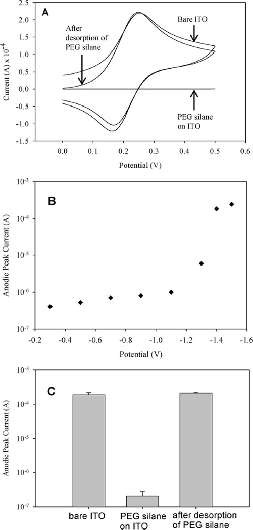
(A) CV used to verify assembly and desorption of PEG silane from ITO. Disappearance of anodic and cathodic redox peaks in the cyclic voltammogram of PEG silane-modified ITO surface points to passivation of electrode with PEG silane layer and prevention of electron transfer across the electrolyte–electrode interface. Ferricyanide redox peaks comparable in amplitude to bare ITO surface were observed after desorption, pointing to the removal of the passivating PEG silane layer and resumption of the electron transfer across electrolyte–electrode interface. (B) PEG silane-modified ITO electrodes were stimulated by applying potentials ranging in values from −0.2 to −1.4 V for 60 s. Ferricyanide CV was then carried out for each applied potential and the values for anodic peak current were recorded. Low peak current values were observed for applied voltage range of −0.2 to −1.1 V. Application of −1.4 V vs Ag/AgCl reference resulted in a 100-fold increase in anodic peak current indicating removal of the PEG silane layer. (C) A plot of anodic peak current for bare, PEG silane-modified and PEG silane-stripped ITO electrodes from three (n = 3) separate experiments.

