Abstract
From the first applications of AT-cut quartz crystals as sensors in solutions more than 20 years ago, the so-called quartz crystal microbalance (QCM) sensor is becoming into a good alternative analytical method in a great deal of applications such as biosensors, analysis of biomolecular interactions, study of bacterial adhesion at specific interfaces, pathogen and microorganism detection, study of polymer film-biomolecule or cell-substrate interactions, immunosensors and an extensive use in fluids and polymer characterization and electrochemical applications among others. The appropriate evaluation of this analytical method requires recognizing the different steps involved and to be conscious of their importance and limitations. The first step involved in a QCM system is the accurate and appropriate characterization of the sensor in relation to the specific application. The use of the piezoelectric sensor in contact with solutions strongly affects its behavior and appropriate electronic interfaces must be used for an adequate sensor characterization. Systems based on different principles and techniques have been implemented during the last 25 years. The interface selection for the specific application is important and its limitations must be known to be conscious of its suitability, and for avoiding the possible error propagation in the interpretation of results. This article presents a comprehensive overview of the different techniques used for AT-cut quartz crystal microbalance in in-solution applications, which are based on the following principles: network or impedance analyzers, decay methods, oscillators and lock-in techniques. The electronic interfaces based on oscillators and phase-locked techniques are treated in detail, with the description of different configurations, since these techniques are the most used in applications for detection of analytes in solutions, and in those where a fast sensor response is necessary.
Keywords: QCM, electronic interfaces, oscillators, detection, piezoelectric sensors
1. Introduction
AT quartz crystal microbalance (QCM) sensors are becoming into a good alternative analytical method in a great deal of applications. They have been extensively used as QCM sensors in gaseous media [1]. However, from the first works, in the beginning of 80's [2], demonstrating that the QCM could be also used for liquid-phase [3], the use of the crystal resonator has been extended to numerous applications in different fields like electrochemistry and biology. Before the extension of the QCM sensor to contacting viscoelastic media [4], few works described the use of the quartz sensor under liquid conditions [5-8]. The complete physical description of a viscoelastic load in contact with the quartz crystal resonator (QCR) has allowed the study of mechanical properties of different materials coated on the surface of the sensor, like viscoelastic properties of polymers [9, 10]. In these cases concepts like “acoustically thin” or “acoustically thick” coatings are of fundamental importance [11]; in case of a thick viscoelastic film in contact with a liquid, a complete characterization of the sensor, together with alternative techniques, is necessary for a comprehensive explanation of certain phenomena involved during the experiments [12]. On the contrary, for acoustically thin films, great simplifications can be done in the physical model and the extraction of the physical properties of interest is simple by appropriate characterization of the sensor [12, 13]. These simplifications can be done in a great deal of applications such us: fluid physical characterization, for both Newtonian and/or viscoelastic fluids [12, 14, 15], charge transfer analysis for studying the behaviour of conductive polymers in electrochemical processes [16], detection of immunoreactions and the development of biosensors [17-28], etc. However, even in the simplest cases, sensor characterization should be performed through suitable electronic interfaces that must be able to accurately measure and to monitor, even continuously, appropriate sensor parameters associated with the physical properties to be evaluated.
In general, the following steps are involved in sensor applications: (a) measurement of the appropriate sensor parameters, (b) extraction of the corresponding physical parameters, related to the model selected for the specific application, starting from the measurements in the previous step, and (c) interpretation of the physical, chemical or biological phenomena which enable to explain the extracted parameters of the selected model. Step (a) is very important because an erroneous sensor parameter characterization can lead to a misinterpretation of the phenomena involved during the experiment. This problem occurs in thickness shear mode (TSM) microbalance sensors, when significant changes in the acoustic load or in the parallel capacitance of the sensor occur during the experiment, if appropriate electronic interfaces are not used. These effects are accentuated in the case of heavy acoustic loads and particularly happen when oscillators are used as QCM drivers [29].
For in gas/vapour phase applications the resonator maintains a high Q factor and oscillators are the best choice for sensor monitoring; no special requirements are necessary different from classical quartz oscillators based on the well-known Pierce, Colpitts, Miller, etc., configurations. For sensor-array it would be advantageous to have the sensing face of the resonator grounded to avoid the coupling or “cross-talk” among the oscillators, but even this recommendation has been demonstrated to be unnecessary if a certain level of isolation is maintained between the circuits [30].
Application of QCM sensors under in-liquid phase conditions is very much challenging and this review will be focused on them. The limitations of different electronic interfaces in relation to the application will be introduced. The application will be evaluated as a function of a change in the measuring parameters. Thus, it is first necessary to define the parameters of the QCR system to be measured.
2. A Suitable Electrical Model for a QCM Sensor
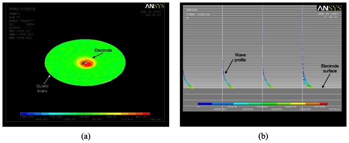
A shear strain is induced in an AT-cut quartz crystal when an alternating-current (AC) voltage is applied across it through opposing electrodes deposited on its surfaces. It generates a transversal acoustic wave propagating through the quartz to the contacting media. Figure 1a (video avi file) shows the shear strain induced on an unperturbed 10MHz AT-cut QCR, scaled in time, recreated with a finite element model (FEM) software (ANSYS). The shear strain goes from negative values (blue color) to positive ones (red color) Figure 1b shows the shear wave propagating on the contacting liquid using the same QCR and the same software.
Figure 1.
(a) Video recreation, made with FEM software (ANSYS), of the shear strain induced in a 10MHz QCR by an alternate field applied through opposing electrodes deposited on its surfaces, (b) video of the shear wave generated by the resonator into the liquid recreated with ANSYS.
The mechanical interaction between the resonator and the contacting media influences the electrical response of the device. This permits the use of the resonator as a sensor device to detect changes in the physical properties of the contacting media.
In order to treat the sensor as a component included in electronic circuits and to be able of analyzing its performance in relation to the external circuitry, an electrical model appropriately representing its impedance would be very useful.
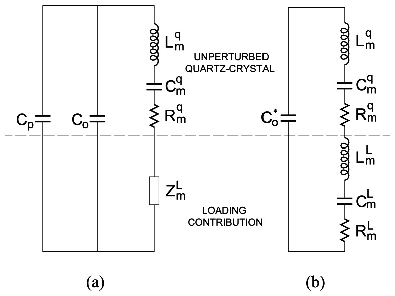
The loaded quartz can be appropriately described by the lumped element models in Figure 2 and, in this way, be included in electronic circuits as an additional component. These models are, in fact, approximations of the TLM (Transmission Line Model) [31], but they are enough for describing the problems associated to the different systems in relation to specific applications.
Figure 2.
Equivalent circuit models for loaded QCR: (a) lumped element model (LEM), and (b) extended-Butterworth Van-Dyke (BVD) model.
For our purposes, it is not necessary to know the expressions relating , , , (unperturbed quartz resonator) and (loading contribution) to the physical and geometrical properties of the quartz and load and they can be found elsewhere [13, 31-32]. can be split under certain conditions into the lumped elements , and as described in Figure 2b[32].
The equivalent circuits in Figure 2 correspond to the typical configuration of only one face of the sensor in contact with the load, which is common for most of in-liquid applications.
Different equivalent models have been described depending on the specific electrode shape and experimental setup [33]; however the equivalent circuits in Figure 2 are the most popular and can be used to represent the most common sensor set-ups as well as for modeling the behavior of the sensor in an electronic circuit like, for instance, an oscillator.
Throughout this article we will make use of the extended BVD equivalent model to study the driver/sensor combination, but it will not affect the generality of the results.
3. QCM Sensor Parameters
To discuss the problem associated with the different electronic systems used to characterize the sensor, it is necessary first to define the parameters to be measured for an appropriate evaluation of the sensor response. The need to know the magnitude of the different parameters will depend on the specific application and on the electronic interface used. When a complete characterization of the sensor is necessary, the different parameters have to be measured and appropriate electronic interfaces must be available, for instance, impedance or network analyzers. Fortunately, there are a great deal of applications where a complete characterization of the sensor is not necessary, and only “key” parameters of the sensor need to be monitored in order to obtain the desired information, for example, applications where the use of a simple oscillator and the monitoring of the oscillating frequency shift is enough. Many of these applications fall in the area of QCM applications in solutions, such as in some piezoelectric biosensors experiments, or for liquids characterization.
With the aim of covering general cases the different sensor parameters for a complete sensor characterization are introduced next:
Parameters , , and of the unperturbed resonator equivalent model can be determined with impedance or network analyzers by measuring the electrical response of the unperturbed resonator over a range of frequencies near resonance, and fitting the equivalent-circuit model to these data. If an impedance analyzer is not available, the corresponding standard [34], or an alternative method described elsewhere [35], can be used. A more accurate determination of can be made at a frequency as high as the double of the resonant frequency [36]. From this analysis the following characterization parameters can be extracted:
fs: motional series resonant frequency (MSRF) of the unperturbed resonator. It is defined as the frequency at which the motional reactance vanishes and corresponds to the following expression for the BVD equivalent circuit:
| (1) |
The maximum conductance frequency monitored by impedance analyzers is very close in most practical cases to the MSRF [15].
hq: quartz thickness. It can be determined from:
| (2) |
where is the piezoelectrically stiffened elastic constant, c66 is the elastic constant, e26 is the piezoelectric stress constant, ε22 is the permittivity, Ko is the lossless effective electromechanical coupling factor, n (n = 1, 3, 5,..) is the harmonic resonance of quartz, ρq is the quartz density and ωs=2πfs.
The quartz thickness calculated through (2) is actually an “effective” quartz thickness that includes the effect of the electrodes, since the resonance frequency ωs is the measured frequency of the sensor with electrodes.
Co: static capacitance, shown in Figure 2a, arises from electrodes located on opposite sides of the dielectric quartz resonator. This capacitance does not include parasitic capacitances external to the resonator (Cp) which do not influence the motional parameters [13]. Static capacitance can be determined from the values of or through the following relationships:
| (3) |
| (4) |
AS: effective electrode surface area. It can be determined from C0 and hq along with the quartz permittivity from:
| (5) |
Its value is necessary in applications involving film thickness.
The determination of the effective electrode area is not a simple task, since it does not necessarily correspond to the electrode area. Actually the effective sensitive area of the sensor could be smaller than the electrode area – in case of a non-perfect overlapping of the faced electrodes – or even bigger – in case of contacting with liquid media [37]. It also comes from the fact that the magnitude of C0 is not either easy to evaluate [38]. Sometimes the effective sensitivity is calibrated with the sensor working in the solution [12].
Cp: parasitic parallel capacitance, external to the resonator. Cp = Co* − Co. Its value is useful in applications where the influence of the dielectric properties of the load have to be accounted for [33]. Some times especial electrode configuration [39] or different excitation principles [39, 40] are used to enhance relevant physical properties of the material under investigation, namely the electrical parameters permittivity and conductivity. In these configurations both the static and parasitic capacitances change and their magnitudes strongly depend on the electrical properties of the material under investigation.
These parameters of the unperturbed resonator are useful in some applications where the unperturbed state of the quartz is the reference state like, for instance, in liquid property characterization. However, in most applications the reference state is not the unperturbed state, and because these parameters can change with the load [38, 41] it is better to take as reference the sensor parameters just before the beginning of the process to be monitored. For example, in electrochemical applications the sensor is in contact with an electrolytic solution, it is to say with a Newtonian liquid of known characteristic impedance and, therefore, this is the state to take as reference. This can be done by calibrating the “unperturbed” sensor parameters for assuring the best fitting between the conductance computed from the TLM, for the known characteristic impedance corresponding to the contacting semi-infinite Newtonian medium, and the experimental conductance plot taken from an impedance or network analyzer [38].
In some other applications such as in piezoelectric biosensors [28, 42] where the losses, mainly due to the contacting solution, are expected to be maintained constant and only the resonance frequency shift is the parameter of interest, the resonant frequency of the sensor in contact with the solution prior to the beginning of the detection process is taken as reference. This value establishes a reference base line accounting for all the non-ideal effects, and allows the evaluation of very tiny frequency changes due to the biological interaction in the coating-liquid interface if appropriate environmental control is held.
Figure 2b shows that the loading contribution can be characterized by the elements , and of the motional branch. A change in both and produces a change in the MSRF. On the other hand, changes in the loading properties are also reflected on changes in the motional resistance , which does not produce MSRF changes. Thus, both MSRF and motional resistance are useful and necessary parameters for sensor characterization.
In addition, it is important to state that the majority of the simpler models derived from the most comprehensive TLM, such as the Lumped Element Model (LEM) [43], or the extended BVD model [13, 32], assume that the resonator operates around the MSRF. Furthermore, it is important to mention that most of simpler equations used to relate frequency and resistance shifts to the properties of the load have been derived assuming that the resonator is oscillating at its true MSRF. Thus, measurements of loading-induced frequency changes made with the resonator operating at a frequency different from the true MSRF could not agree with the models derived for QCM sensors. This discrepancy is specially pronounced when the resonator is loaded with heavy damping media.
Another characteristic which makes the MSRF more interesting than other frequencies is that its value is independent of parallel capacitance changes.
For all that mentioned, the MSRF and the motional resistance are parameters of the loaded resonator to be measured.
However, it is important to notice that only these two parameters are not always enough for a complete determination of physical parameters of interest of the load under study. In general, more than two unknowns are present in quartz sensor applications; in these cases a complete characterization of the admittance spectrum of the sensor can be useful. This characterization of the complete admittance spectrum can only be done with admittance spectrum analyzers like impedance or network analyzers, or specially adapted circuits which can operate in a similar way; but even with a complete characterization of the sensor admittance spectrum around resonance, the resolution of the problem of extracting the physical parameters of the load starting from the electrical parameters of the model is not clearly solved, depending on different aspects like the accuracy of the experimental data, the suitability of the physical model selected to describe the real process, the accuracy of the electrical model used for describing the physical model, the fitting algorithms used, etc, [12, 38]. Therefore, since the admittance spectrum characterization does not clearly solve the complete problem of physical parameters extraction and requires a more sophisticated instrumentation, the researchers have made great efforts to design electronic interfaces for monitoring, as accurately as possible, the two important parameters of interest already mentioned: the MSRF and the motional resistance.
Then, the problem associated with the measuring system will be discussed in relation to the accuracy in the determination of these parameters of interest.
4. Systems for Sensor Parameter Characterization
We will focus this discussion on the interface circuits currently used for sensor characterization which are based on the following principles: network or impedance analysis, impulse excitation or decay methods, oscillators and lock-in techniques. Finally, some requirements and interfaces for fast QCM sensor applications are described.
4.1. Impedance or Network Analysis
Since the problems associated with oscillators for the accurate monitoring of the right frequency of the QCR sensors were described [5, 6, 33], the use of admittance spectrum analyzers to characterize the quartz sensor was extended [4, 44-47]. Nowadays this technique is habitually used for sensor analysis under laboratory conditions having its advantages and disadvantages.
Impedance or network analyzers measure the electrical impedance or admittance of the quartz sensor over a range of frequencies near resonance for a complete characterization of the device response. As a test instrument, an impedance analyzer has the following advantages in evaluating the sensor response:
The device is measured in isolation and no external circuitry influences the electrical behavior of the sensor.
Parasitic influences can be excluded by calibration due to passive operation of the sensor.
Differentiated information in relation to diverse contributions of the load can be obtained by measuring both the conductance and the susceptance of the sensor over a range of frequencies around resonance.
However, several inconveniences remain when using this technique for sensor applications [48]:
Its high cost and large dimensions of the associated equipment prevent its use for in situ or remote measurements.
The connection between the sensor and the equipment is sometimes difficult to accomplish such as in electrochemical or biological applications where it is convenient to ground one of the quartz electrodes.
It is not suitable for simultaneous multiple sensor characterization. Sometimes a multiplexing interface is used for a sequential connection of different sensors to the same analyzer, but it can perturb the device response.
On the other hand, the impedance analyzer can determine with high accuracy the MSRF and motional resistance of the unperturbed quartz sensors as reference values. The MSRF is obtained by measuring the frequency corresponding to the conductance peak around resonance. The motional resistance is determined as the reciprocal of the conductance peak value. The evaluation of the MSRF and the motional resistance in this way is based on the suitability of the BVD model for characterizing the sensor response. In BVD circuits the relationships between MSRF and maximum conductance frequency and between the motional resistance and the reciprocal of the conductance peak value are exact. For an unperturbed resonator, the BVD circuit can very accurately represent the device response. Additionally, the range of frequencies in which the resonance happens is very narrow and therefore the frequency resolution of the instrument is very high.
However, for heavy damping loads the quality factor of the device is considerably reduced and the resonance range broadens; this reduces the frequency resolution as well as the suitability of the BVD circuit for representing the sensor response. The determination of the MSRF and motional resistance by using the mentioned relationships is not as accurate as for the unperturbed situation, but remains accurate enough for these applications in which the sensor can be used [15]. On the contrary, the determination of BVD parameters for high damping loads does not give additional information apart from the parallel capacitance, which can be measured more appropriately at double of the resonant frequency. Furthermore, the MSRF determination from the motional components (1) can produce great errors depending on the algorithm used for the motional parameters extraction. An option better than a direct reading of the conductance peak and its frequency from the discrete data of the conductance plot measured by the impedance analyzer, is to fit these data to a Lorentzian curve and to obtain this information from the maximum of the curve; this provides more accurate results in case of heavy loaded quartz sensors. Additionally, an alternative parameter, probably more accurate than the motional resistance for measuring the damping and quality factor Q of the loaded sensor is the half power spectrum of the resonance; a relationship among all these parameters can be obtained through the BVD model [31]. In transient dissipation instruments using the decay method (see section 4.2 below) the dissipation factor D, reciprocal of the quality factor, is habitually used.
4.1.1. Adapted Impedance Spectrum Analyzers
To circumvent the drawbacks of classical impedance or network analyzers, important efforts have been made to adapt the principle of operation of these reference instruments into smaller electronic boards configured for the specific features of QCR sensors [49-54].
These adapted systems maintain similar specifications to high performance impedance analyzers in the range of frequencies and impedances of typical QCR sensors while improving the portability.
The characteristics of these circuits make them appropriate for most common QCM applications. These adapted circuits are optimized for fast data measuring and acquisition in comparison with classical analyzers and allow measuring and acquiring each datum of impedance between 1 and 5 ms [50]; this means that each complete impedance spectrum can be recorded between 1 and 5 s, assuming 1000 frequency points. This acquisition time is enough for most applications, at least in the case of 1 s. However, they are not appropriate for fast QCM applications where a very fast changing frequency is necessary to be monitored [16, 55].
Alternatively, simpler systems have been developed following the principle of passive interrogation of the sensor used in impedance analyzers; it is to say, by sweeping the frequency of the interrogating signal around the frequency range under study. However, instead of being designed for recovering the information associated with the conductance and susceptance spectra of the sensor around resonance, which is more involved in terms of electronic design, they acquire the representative magnitudes of voltages associated with a “voltage transfer function” in which the impedance of the sensor takes part. Then, the impedance of the sensor is replaced by an appropriate model whose parameters are fitted to the experimental voltage transfer function acquired [56, 57].
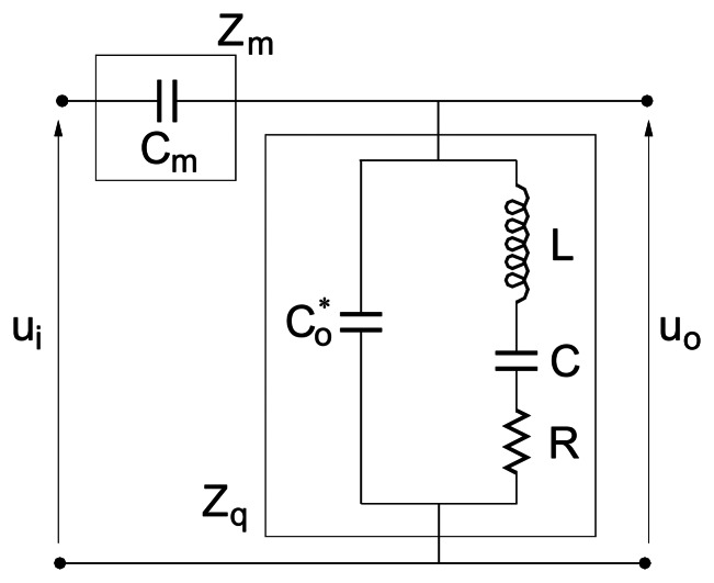
In the transfer function method used by Calvo and Etchenique, for instance, the sensor takes part of an impedance divider where the other impedance in the divider is known [57]. Figure 3 shows the impedance divider where the sensor has been characterized by its equivalent BVD circuit.
Figure 3.
Impedance divider for the transfer function method used in reference [57].
A sinusoidal signal applied at the input sweeps a range of frequencies around the resonant frequency of the sensor; the average values of the input and output voltages are measured and acquired with an analog/digital converter and captured with a computer. Thus, an experimental measure of the absolute value of the voltage transfer function is obtained in the range of frequencies considered.
The theoretical transfer function is used to find the set of parameters that best fit to the experimental data. It is assumed that the motional capacitance remains constant, the rest of parameters C0, L and R are obtained by a non-linear fitting with appropriate initial conditions.
Finally the authors of this technique noticed the advantage of using a capacitor Cm instead of a resistor as the other branch of the voltage divider, as shown in Figure 3. In this context the theoretical transfer function is:
| (6) |
A very interesting approach has been recently described by Kankare et al [58]. The set-up includes the QCR sensor in series with a capacitor, as described in the previous approach; however, the signal used to interrogate the voltage divider is a double-sideband suppress carrier amplitude modulated signal whose carrier is swept around the resonance frequency range. This strategy confers special characteristics to the system that are worth to treat in more detail.
The working principle of the interface is depicted in Figure 4 where the voltages at the inputs of the multiplier are given by the following expressions:
| (7) |
| (8) |
where ω+= ωc+ωm, ω-= ωc-ωm and the functions f(ω) and g(ω) are the real and imaginary parts of the impedance divider transfer function given by de following expressions:
| (9) |
where YQ is the admittance of the sensor at the interrogating frequencies.
Figure 4.
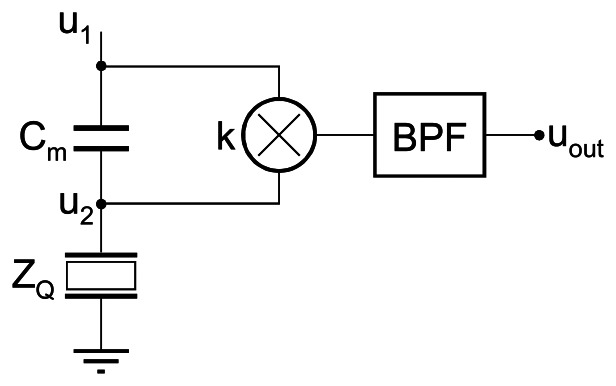
Schematic diagram of the interface. Adapted from [58].
As can be seen the sensor is simultaneously interrogated at two frequencies ω+= ωc+ωm and ω-= ωc-ωm which move together with the sweeping of the carrier. The frequency shift between the interrogating signals (2ωm) can be easily controlled by appropriate selection of the frequency of the modulating signal that is maintained constant during the impedance test.
After multiplying the input signals and removing the high frequency and dc components by appropriate filtering (demodulation of u2), the following low frequency signal remain at the output:
| (10) |
The demodulated signal is formed by a couple of two coherent terms of frequency 2ωm whose amplitudes have the information about the sensor impedance through (9). By modeling the motional impedance of the sensor with the LEM [43] and estimating the parameters of the resonator in the unperturbed state, the authors can obtain the real and imaginary parts of the surface load impedance by non-linear fitting of the data corresponding to the amplitude of the component in quadrature g(ω+)-g(ω-).
This configuration has three advantages in comparison with the classical impedance analysis operation:
The information of the phase and magnitude of the sensor impedance is carried out in the amplitude of low frequency signals; this makes easier and more accurate their acquisition.
Because the signal of interest is formed as the difference between two coherent signals, any additive source of noise is cancelled.
The differential form of the signal permits to increase the sensitivity in case of heavy loaded resonators. Effectively, within a certain range, an increase in the modulating frequency increases the difference g(ω+)-g(ω-); it creates an amplifying effect while maintaining the noise and then the signal to noise ratio is improved.
This original method could be in fact considered as an improvement of classical impedance analysis operation and can be used for any QCR sensor application with the exception of fast QCM at high operation rates.
4.2. Decay Methods
Impulse excitation and decay methods are based on the same principles [29], however the decay method is easier to apply in practice.
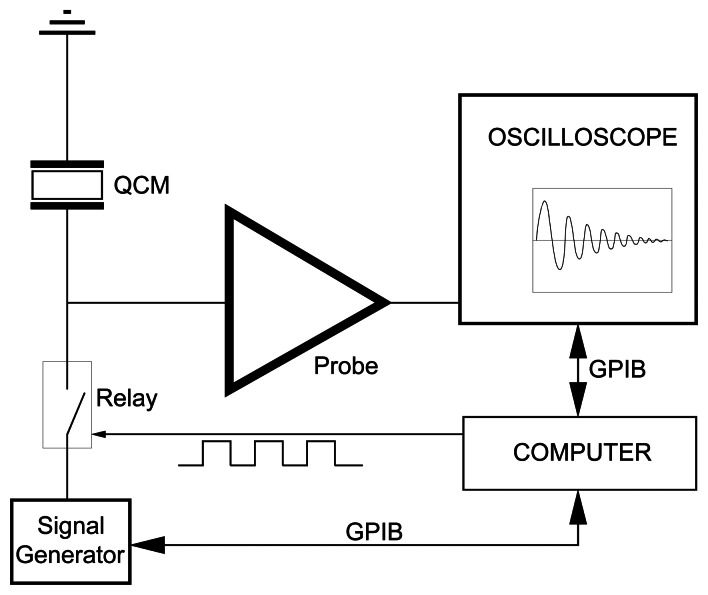
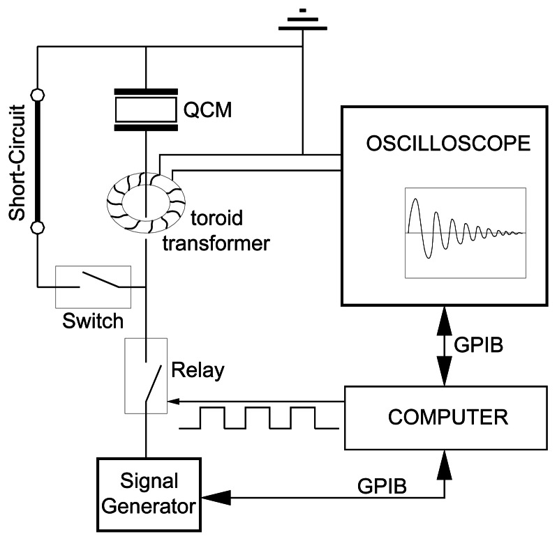
The schematics of the experimental set-ups for the decay method are depicted in Figures 5 and 6 for the excitation of the parallel and series resonant frequencies, respectively [59, 60].
Figure 5.
Experimental setup used to measure the parallel resonant frequency and the parallel dissipation factor (Adapted from [61]).
Figure 6.
Experimental setup used to measure the series resonant frequency and the series dissipation factor (Adapted from [61]).
In this technique the piezoelectric resonator is excited with a signal generator approximately tuned to the frequency of the desired harmonic. Then, at t = 0 the signal excitation is eliminated by opening the appropriate relay. At this moment, the voltage or current, depending on whether the parallel or series resonant frequency is excited according to the electrical setup [61], decays as an exponentially damped sinusoidal signal, mathematically expressed by:
| (11) |
where Ao is the amplitude of the magnitude at t = 0; φ is the phase and f is the frequency given by:
| (12) |
where fi is the MSRF of the loaded QCR, fs, or the parallel resonant frequency, fp, given by:
| (13) |
In (12), it has been implicitly assumed that the quality factor is the same for both series and parallel mode, and is given by:
| (14) |
In the series excitation mode (Figure 6), the parallel capacitance effect is eliminated by short-circuiting and the frequency of the damping oscillations is very close to the true MSRF. This is one of the principal advantages of the method.
The accuracy of the decay method is high, provided that the measurement of the frequency and the envelope are obtained with high accuracy, which becomes complicated for strongly damping loads.
This technique reduces the cost of the instrumentation in comparison with network analysis; however, the quality and dimensions of the required equipment still remain high, mainly if an accurate determination of the frequency and the envelope of the exponentially damped sinusoidal is necessary. Therefore, this method is more appropriate for laboratory environment than for sensor applications and becomes more sophisticated when simultaneous multiple sensor characterization at high sampling rates have to be performed.
Recently, the decay method has been introduced with two simultaneous excitation frequencies corresponding to two harmonics of the resonance frequency. One of the harmonics is used for a continuous evaluation of the frequency and damping of the sensor, while the other harmonic is used for perturbation purposes by changing the driving amplitude.
This approach allows the analysis of binding reactions under controlled perturbation conditions, while the sensor is simultaneously characterized by monitoring the resonance frequency and the damping with the other testing signal [62].
4.3. Oscillators
In this section the field of oscillators for in-liquid quartz sensor applications is covered. Some fundamentals on LC oscillators are necessary to understand some concepts introduced here. A didactic explanation of these concepts as well as the typical modes of operation of a crystal controlled oscillator: parallel and series modes, can be found elsewhere [29, 63-68].
4.3.1. Problem associated with the determination of the MSRF and the motional resistance
The systems described in previous sections passively interrogate the quartz resonator and, with an appropriate interface, the desired characteristic parameters of the sensor are measured in isolation, i.e., the external circuitry does not interfere with the sensor response. This is the greatest advantage of the methods described.
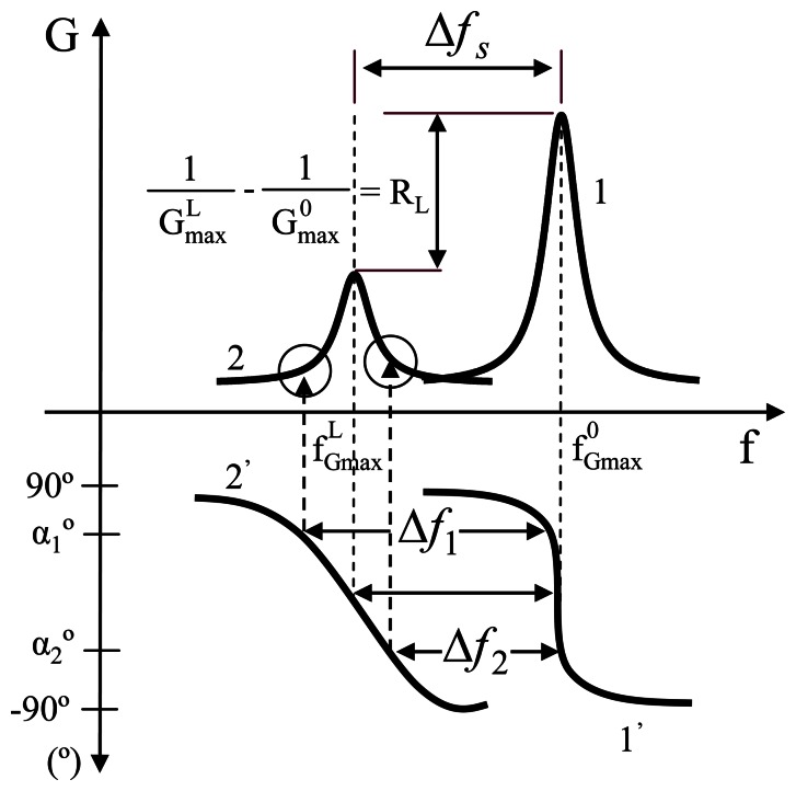
However, oscillators' output frequency depends on the specific loop gain and phase oscillating conditions; therefore different oscillators can provide different output frequencies for the same experiment depending on the specific designed oscillating conditions. This effect which could not be easily recognized can lead to the risk of severe misinterpretations of the authentic frequency shift of the sensor characteristic frequency. The problem is qualitatively depicted in Figure 7. As it can be noticed, different frequency shifts, Δf1 and Δf2, would be provided by oscillators with different sensor phase oscillating conditions, α1 and α2, between two different instants of an experiment for which the conductance and phase responses of the sensor around the resonance are given by the plots 1, 1′ and 2, 2′ for instants 1 and 2 respectively. As it can be understood this effect is a consequence of the decrease of the steepness of the phase response of the sensor as a consequence of the damping effect due to the load. The conductance value of the sensor is also different at the two phase oscillating conditions, α1 and α2; this also implies an error in the characterization of the sensor damping when the conductance is taken as a parameter for its characterization.
Figure 7.
Qualitative description of the problem of QCM sensor characterization.
The appropriate frequency and conductance to be monitored are those corresponding to the series resonance of the motional branch of the circuits in Figure 2, which are, for most cases, very close to those of the conductance peak of the sensor as shown in Figure 7 (fGmax and Gmax). However, this point of the admittance response of the sensor is not univocally determined at a specific phase condition, Φ(fGmax), that depends on both the total motional resistance Rm and the total parallel capacitance C0* =C0+Cp through (15). Therefore, a different strategy must be designed to continuously track this characteristic point.
| (15) |
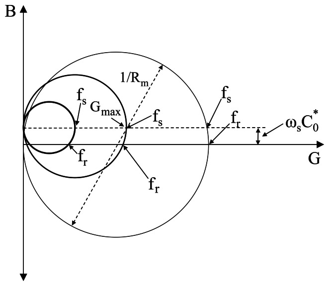
Figure 8 shows, qualitatively, the typical locus of the admittance of a quartz sensor under different loads. As it can be noticed, the high admittance zero-phase frequency, fr, gives a good approximation of the maximum conductance frequency for low acoustic loads; however, when the acoustic load and/or the parallel capacitance increase the zero-phase frequency can not be longer considered as the maximum conductance frequency. On the contrary, if the parallel capacitance is compensated the zero-phase is the appropriate tracking condition for the maximum conductance monitoring.
Figure 8.
Qualitative description of the change in the sensor admittance due to different loads using the admittance locus diagram.
As described, the oscillator frequency is dependent not only on “mass loading” (motional inductance) but on “dissipation” (motional resistance). This must be taken into account and carefully considered when using an oscillator in a specific application where the physical properties of the load can change, producing changes in both the mass loading and dissipation.
In a great deal of applications in which the quartz resonator is used as a sensor, an additional magnitude to the MSRF shift is necessary in order to discriminate different physical contributions [13]. In what concerns to oscillators, many designs incorporate an automatic gain control (AGC) system for the measurement of the activity [69] of the quartz sensor at resonance [70-75]. The AGC system tries to maintain the level of the signal constant in a selected point of the oscillator. With this purpose, it provides a voltage (AGC voltage) that modifies the gain of the amplifier so as to maintain the signal level in the selected point constant in relation to a reference voltage. In many of these designs proportionality between the change in the AGC voltage and the change in the motional resistance is claimed [48, 72-73, 75]. In some of these AGC systems the proportionality is justified only from a physical point of view [73]. In others, mathematical expressions in which some simplifications were made show this proportionality [72], although it is also shown that this proportionality is lost in some cases [76].
It can be shown that even in the most ideal situation it is very difficult to ensure that the voltage shift provided by an AGC system included in an oscillator is proportional to the change in the motional resistance; unless the parallel capacitance of the sensor is suppressed or compensated. This demonstration can be found elsewhere [77].
The most important aspects concerning the problem associated with oscillators as electronic drivers for QCMS have been treated. It has been shown that although the simplicity of an oscillator makes this device very attractive for sensor applications, some limitations remain. These limitations have to be taken into account in the interest of accuracy and they should be kept in mind in any new work that looks for the simplicity and autonomy of oscillators for sensor applications.
4.3.2. Oscillators for QCM Sensors. Overview
In spite of the drawbacks of oscillator circuits for QCR sensor applications mentioned above, their low cost of the circuitry as well as the integration capability and continuous monitoring are some features which make the oscillators to be a good choice for most chemical sensor applications. In this section an overview of representative oscillator approaches proposed in the last two decades for improving the accuracy in the tracking of the appropriate frequency and damping of the resonator sensor, under loading conditions, is presented.
For in-liquid phase or heavy loaded sensor applications, the Q factor of the resonator is strongly reduced; for instance, for AT QCR at 10MHz the Q factor is reduced from 80.000 to 3.000 with only one face in contact with water. Moreover, the damping, and then the Q factor, can change during the experiment. This reduction implies that special care must be taken in the design of the oscillator: on one part in the selection of the more suitable configuration, which will be treated in detail throughout this section, and on the other part in the selection of the components of the oscillator circuit, mainly in terms of stability of their electrical characteristics as a function of changes in external variables such as temperature, humidity, etc. The reason is that for high Q factor, changes in the phase response of the sensor due to external conditions are easily compensated with very small changes in the frequency of the resonator, and appear in the signal frequency as a small noise and/or drift. However, for low Q factors small changes in the phase response of the rest of the components in the loop of the oscillator need to be compensated with bigger shifts in the oscillator frequency. In these cases, the noise and drift are not negligible and a good control of the external variables has to be done for minimizing this problem. Therefore, extreme care must be taken into account in the design of the cell as well as in the control of the surrounding; temperature has to be maintained as stable as possible by thermostatic shields, the electronic noise of the circuit should be reduced as much as possible even by cooling the circuit at low temperatures, the sensor should be protected against vibrations with appropriate inertial systems, etc. This aspect, which is not normally taken into account, is very important for decreasing the level of noise in oscillators and is one of the most important aspects for increasing the resolution and sensitivity of QCR sensors by increasing the frequency [78-80]. Letting this aside, the selection of the appropriate oscillator configuration is, of course, another very important aspect.
In 1980 the work of Konash and Bastiaans [2], demonstrating that the QCM could be also used for liquid-phase, and that it was possible to maintain the stability of a crystal oscillator with the resonator one-face in contact with a liquid medium, paved the way for numerous applications in different fields like electrochemistry and biology. This work, although with some poor results in terms of comparison with well-supported techniques, opened the way of using the quartz crystal as sensor in fluid media. The physical explanation of why the resonator could maintain the oscillation under the tremendous load of the contacting liquid was given later on by the well-known work of Kanawaza and Gordon [3].
Until the important work of Reed et al [4], in 1990, extending the application of the AT-cut quartz crystal to contacting viscoelastic media, few works described the use of the quartz sensor under liquid conditions [5-8]. The use of oscillators was a common practice on these days and the attention was quickly paid on these interfaces to explain some inconsistencies in the experiments; for instance, different frequency shifts were obtained with different oscillators in apparently the same resonator conditions [5, 6]. The need for a common reference of the working phase of the QCR sensor in the oscillators used for in-liquid applications was posed, and 0° for the phase of the sensor under oscillating conditions was proposed [6]. It was also probed that the zero-phase condition not always exits for the loaded sensor [67] and then, the use of impedance analysis was generalized as an accurate but expensive interface for sensor characterization [4, 44-47].
In the beginning of 90's Barnes analyzed most of the typical oscillators used until then for in-liquid sensing [33]. In this work a clear explanation is included about the reasons of why different oscillators can provide different monitoring frequencies under the same sensor conditions.
The two typical operational modes of oscillators are discussed: the parallel mode has a less restrictive range of operation than the series mode and it can be designed to force the resonator to oscillate under heavy load conditions, on the other hand the sensor phase condition is more difficult to control.
Barnes work introduced the main aspects, which would be in the near future the “key” points in the design of oscillators for QCR sensors: a) one face of the resonator should be grounded for electrochemical or biological applications and for a better control of the parallel capacitance, b) the evaluation of the motional series resistance would be very useful in many applications, c) an automatic gain control should be implemented to adjust the loop gain for stable operation, and d) the parallel capacitance (static and parasitic components) plays an important role in determining the oscillation frequency, specially in parallel mode configurations [66]. Effectively, the evaluation of the sensor damping played an important role after the work of Martin and Granstaff in 1991 [13], showing that the simultaneous measuring of the frequency shift and motional resistance allowed the discrimination of different contributions on the sensor response: mass and liquid effects. Thus, automatic gain control systems were implemented in oscillators, not only for stabilization purposes but as a mean to evaluate the damping of the sensor, with the limitations mentioned in the previous section. Finally, the parallel capacitance compensation has been one of the key aspects in the last approaches of electronic interfaces for QCM sensor characterization (see next section).
From then on great efforts were made in the design of appropriate oscillators in in-liquid applications. Parallel mode oscillators, operating at strong negative phase conditions (≈-76°) to force the oscillation of the resonator under heavy load conditions were used [70-71]. However, the major efforts were made in the design of series oscillators with the resonator working at zero phase condition and with one face grounded: emitter coupled oscillators [48, 75, 81, 82], lever oscillator [72, 83], active bridge oscillator [84, 85], and balanced bridge oscillators [86, 87].
As it has been mentioned the frequency at which the crystal oscillator is driven depends on the resonator phase condition in the loop. Moreover, the resonator phase condition depends on the working phase of the rest of the components of the circuit in the loop. Since it is not possible to choose the characteristic frequency of the resonator at which the oscillator must oscillate, the other alternative, although not optimal, is to maintain the phase of the sensor in the oscillator as constant as possible for a wide range of loads, at least in this way one would have a reference point in the response of the sensor. To this aim the phase of the rest of the components in the loop should be also maintained as constant as possible, in the frequency range of operation, for a wide dynamic range of loads. A good selection of components and appropriate configurations must be chosen for this aim [68, 72]. Once this requirement is covered, the matter is to decide at what phase the sensor should work for a more ideal operation. The series configuration, at which the sensor ideally works at zero-phase condition, was initially selected.
The reason for developing series oscillators working near resonator zero-phase condition was the assumption that the parallel capacitance has a lower effect on the oscillating frequency near the zero-phase frequency of the sensor. In fact, the MSRF does not depend on the parallel capacitance, and for small loads the sensor zero-phase frequency is very near the MSRF. Moreover, if the parallel capacitance could be compensated, for instance by parallel resonance with a coil at the working frequency, the oscillator would be operating at the true MSRF. However, it is not know “a priori” what will be the oscillating frequency, and the tuning out of the parallel capacitance is not easy to do without additional more involved instrumentation. Thus, the use of a coil for tuning out the parallel capacitance, although theoretically described, is not habitually used. Under these conditions it was found, with some series configurations, that the initial design at zero-phase was not the optimal condition for the usual range of loads. Different works found that the resonator phase condition at which the frequency was reasonably closer to the MSRF, in the most usual range of loads (for motional resistances ranged from 100 to 700 Ω), was -38°±3° [48, 81, 82, 88]. In other cases, although the zero-phase condition of the sensor was desired, the non-ideal characteristics of the circuit components result in a phase condition near the zero-phase condition (≈-6° for the Lever oscillator [72] and ≈-3,5° for the active bridge oscillator [84, 85]. The balanced bridge oscillator is, in principle, able to compensate the parallel capacitance, and then the oscillating frequency is theoretically driven by the condition of zero-phase of the motional impedance [86-87]. Therefore, in ideal conditions the oscillating frequency would be the MSRF. A brief description of the abovementioned oscillator configurations will be next introduced; more details can be found in the given references.
A. Emitter coupled crystal oscillator
Emitter coupled crystal oscillator is one of the configurations which best covers the requirements for driving QCM resonators under liquid conditions.
In an emitter coupled oscillator (Figure 9) two cascade inverting amplification stages are used to provide, ideally, a total zero-phase shift of the loop. A crystal resonator is strategically included in the loop to control the oscillating frequency. In a well-designed crystal controlled oscillator, the gain of the oscillator must be maximized at the desired operating frequency and must be minimized at other frequencies [90].
Figure 9.
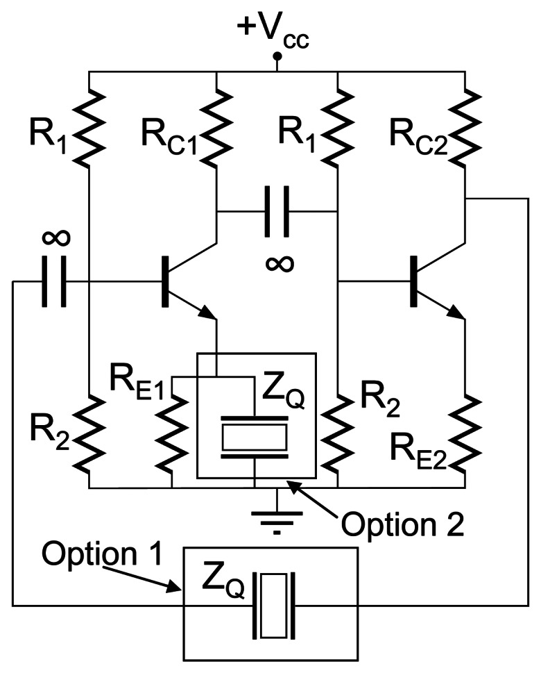
Basic schema of an emitter coupled oscillator configuration in which two possible options for series resonance sensor condition are shown.
For a series resonance condition, the resonator could be connected in two different places as indicated in Figure 9. In option 1 the sensor is in the feed-back path of the loop and controls the oscillation frequency around its zero-phase frequency. Some oscillators have been designed following this approach and successfully proven under liquid operation [68, 89]. However, the resonator connected in the circuit under option 1 has no electrode grounded and, therefore, does not comply with one of the requirements for QCM under liquid conditions, especially for electrochemical applications. Option 2 is a more attractive approach since covers the previous requirement.
For option 2 connexion the gain of the loop will be given by:
| (16) |
In the former equation, it has been assumed that at the oscillating frequency Rei//ZQ ≈ ZQ. On the contrary a RF-choke in series with RE1 can be included for decoupling RE1 at high frequencies.
Therefore, the gain is maximized near the minimum impedance of the crystal around resonance and among resonances the resonance of minimum impedance is preferable. Additional methods to avoid spurious oscillations can be implemented in practical realizations [68, 89].
Assuming ideal behaviour of the circuit, the phase loop condition is also controlled around the zero-phase frequency of low impedance of the resonator according to the previous equation. For slight loads and small parallel capacitances the impedance of the quartz at the low impedance zero-phase frequency is close to the motional resistance (Rm); under these conditions and making Rc1 = RE2 in (16), the loop gain of the system will be:
| (17) |
Thus, the loop gain condition for oscillation (ALoop = 1) will be covered for Rc2 = Rm and the measurement of Rc2, when the system starts the oscillation, provides a method to evaluate the damping of the sensor.
A similar approach has been successfully implemented for liquids characterization and electrochemical applications [81, 82, 88]. However, it was observed that the zero-phase condition was not the optimal condition for oscillation closer the MSRF. A capacitor in parallel with Rc1 allowed to control the phase conditions around -38°±3° which was theoretically demonstrated to be a more optimal phase condition in the usual range of loads [88]. This was also later confirmed in other works [48], although it is clear that the precise manner in which the oscillation frequency tracks better the MSRF depends on the combination of net parallel capacitance, loading and phase-angle [76]. However, as it was mentioned frequency shifts obtained from frequencies different from the MSRF could not be suitable for being used in the resonance models such as the acoustic load concept and Kanazawa or Martin models [31]. For that, it is advantageous to know the oscillation phase of the resonator and a measurement of the damping at this phase, because it could permit to recover the true MSRF and motional resistance [72, 75, 82].
The most critical components in the emitter coupled oscillator, and in general in any oscillator configuration, are the transistors; their temperature-dependent parameters, parasitic capacitances and non-linear amplifications characteristics are some inconveniences which need to be avoided. Fortunately the use of a voltage-controlled current source usually known as Operational Transconductance Amplifier (OTA) can be used almost as an ideal transistor [91, 92].
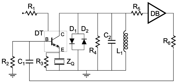
Emitter coupled oscillators have been designed with OTA following the option 1 crystal connexion mentioned in Figure 9 [68, 89]. In Figure 10 the basic schema corresponding to the connexion showed as option 2 in Figure 9 is depicted [48, 75]. A compact design is accomplished by using the OPA660 integrated circuit which includes a diamond buffer (DB) based on an abridged version of the OTA [92]. The non-inverting common-E amplifier based on the OTA and the buffer provide, ideally, a zero-phase rotation of the loop and a loop gain given by [29]:
| (18) |
where rE = 1/gm, being gm the transconductance of the OTA.
Figure 10.
Practical realization of an emitter coupled crystal oscillators with OTA. Adapted from [48].
With the appropriate selection of R4 to cover wide dynamic load ranges, the loop gain is in general greater than the unity and the amplitude stabilization is provided by the antiparallel connected Schottky diodes D1 and D2. The R2-C1 high pass filter allowed the control of the total phase rotation of the loop, once the common-E amplifier gain has been selected with R4 and the OTA transconductance has been fixed by appropriate selection of the biasing point through R1. Finally, the phase rotation was selected at -40° in coincidence with the previous works mentioned above [82, 88]. The tank circuit L1-C2 is parallel tuned around the desired resonance of the sensor and strongly reduces the gain for undesired frequencies, avoiding parasitic oscillation.
The basic circuit in Figure 10 can include a buffer at the output for impedance matching with test instruments. The amplitude stabilization based on diodes can be substituted by an automatic gain control (AGC) system capable to provide, in principle, an evaluation of the damping of the resonator at the resonator phase oscillating condition [75].
B. Bridge oscillators
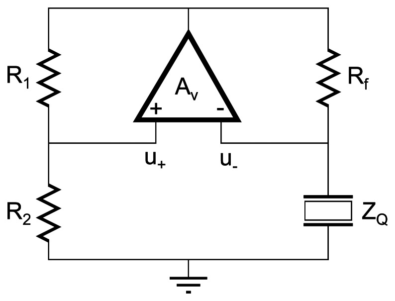
The lever oscillator[72, 76, 83] and the active bridge oscillator[84, 85, 95] are two different approaches of a more general oscillator configuration, the so-called bridge oscillator. The simplified configuration of a standard bridge oscillator (SBO) in introduced in Figure 11. A more detailed and didactic explanation of the concepts introduced next can be found elsewhere [29]. Early references about bridge oscillators (BO) can be found in [93, 94].
Figure 11.
Schematic of a standard bridge oscillator (SBO) configuration.
The loop-gain governing the oscillating condition for the SBO (Figure 11) is easily derived and found to be:
| (19) |
where the positive feedback ratio βp=R2/R1+R2 and the negative feedback ratio βn=ZQ/Rf+ZQ. For oscillation A = 1 and βp>βn.
The phase-loop condition is mainly determined by the difference (βp-βn), assuming that the amplifier does not introduce additional phase shift. The amplifier must provide enough gain for sustaining oscillation; the excess loop-gain is limited under operation by the nonlinear characteristics of the active devices.
For zero-phase resonator oscillating condition, the positive feedback is designed to provide zero-phase shift. Under these conditions the resonator impedance ZQ must be real; therefore, the resonator low impedance zero-phase frequency is excited by the circuit. It should be noticed that at the high impedance zero-phase frequency the negative feedback ratio would increase near to βn ≈ 1, making improbable the oscillation at this frequency.
Under small loading condition, at resonator zero-phase operation, ZQ can be approximated to the motional resistance Rm, but for heavy loads the parallel capacitance effects have an important contribution on the phase-frequency combination. This negative influence must be avoided by appropriate tuning out of the parallel capacitance with, for example, a parallel inductance. In fact, the operating loading range is drastically improved in this way; therefore, from now on, in this section, the impedance of the resonator will be substituted by the motional resistance Rm in the equations.
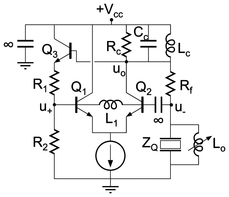
For a practical application of the previous equations, the schematic realization of a standard bridge crystal oscillator is depicted in Figure 12.
Figure 12.
Schematic of a practical realization of a standard bridge crystal oscillator configuration.
The analysis of the small signal equivalent circuit gives the following loop-gain [29]:
| (20) |
where rE = 1/gm, being gm the transconductance of the transistors and the direct gain Av (19) is:
| (21) |
The former equation allows making the following considerations for SBO under liquid loading conditions:
Rf must be selected is such a way to appropriately cover the dynamic range of loads expected in the experiment. Then, according to the maximum value of βn, the magnitude of βp must be selected, but keeping in mind that a very low magnitude of the expression between the brackets in (20) will require a high value of Av which is limited to Rc/2rE.
For heavy loads, the maximum direct gain Av = Rc/2rE must be chosen high enough for exciting oscillation at steady-state.
The excess of gain under operating conditions will be limited by nonlinearities of the amplifiers; in this case the intrinsic emitter resistance rE which is strongly dependent on the signal amplitude and bias point. In the SBO configuration changes in the value of rE can only occur with drastic changes in the oscillating amplitude or by changing the bias point of the active devices under controlled conditions, for instance by automatic gain control (AGC) systems. Because strong changes in amplitude oscillation induce poor frequency stability and noise, it is more appropriate to implement AGC systems to maintain the gain-excess at minimum and to drive the circuit with small amplitude of the oscillation signal; this improves the linearity, the signal noise and the amplitude and frequency stability. Additionally, these AGC circuits allow monitoring of the resonator losses, although increase the complexity of the system.
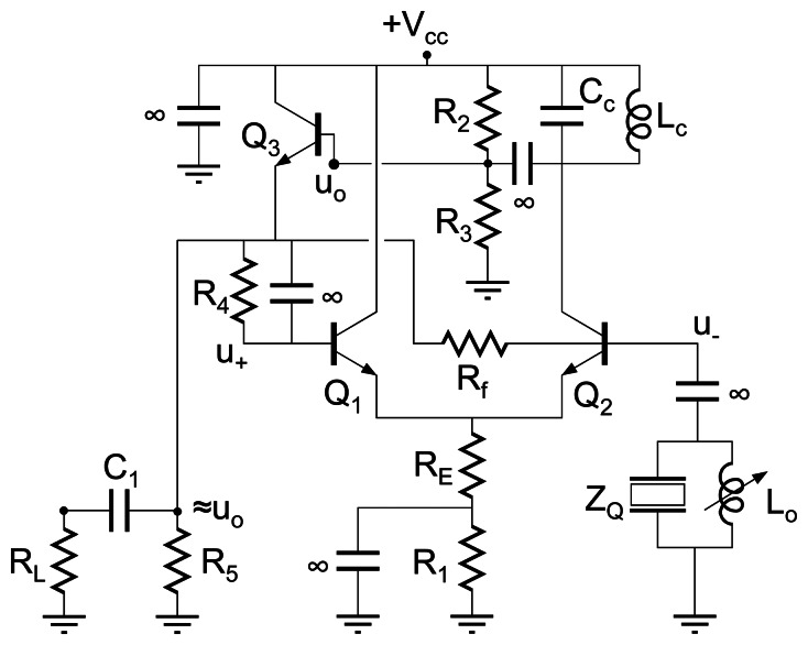
The lever oscillator, whose practical realization is depicted in Figure 13, is in fact a half-bridge oscillator. The loop-gain governing the circuit is, according to (20):
| (22) |
Figure 13.
Practical realization of a lever oscillator configuration.
As mentioned above, βp=1 and the oscillation phase condition is controlled by the negative feed-back path βn which increases with Rm.
The direct gain Av is also “leveraged” by the value of Rm. Effectively, Av increases with Rm; however, this increment is only significant for values of Rf and Rc of similar magnitude to Rm. Even with this increasing effect on the magnitude of Av, strong changes of rE are necessary when resonator losses change in a relative wide loading range. As mentioned, if an AGC is not used to stabilize the oscillating amplitude by appropriate change of the bias point, the oscillator suffers of stability problems, mainly at high frequencies of oscillation [48, 76].
On the other hand, the oscillator ideally works at resonator zero-phase condition; however, when parasitic effects are taken into account the resonator phase at oscillating condition deviates to ≈-6° under usual liquid loading conditions, (Rm>200Ω) [72]. Furthermore, for lower impedances the loop gain is poorly controlled by the resonator and the phase condition is determined by parasitic effects.
The circuit has been successfully proven for in-liquid operation with AGC and it has been noticed that an accurate tuning out of the parallel capacitance is necessary for a proper operation in the typical range of loads [76]. It was also found that when non-perfect parallel capacitance compensation is achieved, a negative resonator phase for oscillating condition fits better the MSRF in a wider range of loads than the zero-phase condition, in coincidence with other in-parallel works [48, 81, 82, 88].
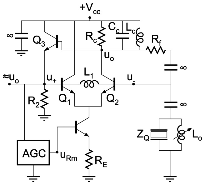
The active bridge oscillator (ABO) [84, 85, 95], whose simplified schematics of a practical realization is depicted in Figure 14, suggests, at first sight, to be a standard half-bridge oscillator; however, the substitution of the current source by a lower emitter impedance RE “degenerates” the half-bridge configuration in a full-bridge oscillator with βp<1 and strongly dependent on the intrinsic emitter resistance rE.
Figure 14.
Schematics of practical realization of the active bridge oscillator.
The analysis of the small signal equivalent circuit gives the following loop-gain equation for the ABO [29]:
| (23) |
where
| (24) |
In the ABO the bias points of transistors Q1 and Q2 are similar as in the case of SBO (R4≈Rf in Figure 14). However under oscillation conditions, the signal amplitudes at the bases are completely different; the base of Q1 has amplitude of oscillation similar to uo while the base of Q2 is operating at a fraction of the output signal amplitude uo. This makes the magnitudes of Av and βp to be a strong function of rE.
For heavy loads, high Rm, Rf must be selected appropriately to cover the loading range, for instance Rf = 2500 Ω; βp must be chosen smaller than 1 with RE of adequate small value to improve the quality factor of circuit in relation to that of the resonator. Once Rf, RE and a representative value of Rm have been determined, the value of rE for A=1 is calculated and the corresponding bias point provided. Under these conditions, an increase of Rm increases u- and reduces the amplitude of oscillation while increases βn; on the other part, the new oscillating condition requires a smaller value of rE to sustain the loop-gain A= 1 which, in turn, increases βp allowing a certain degree of adaptation to a wider range of loads. The amplitude stability is improved as well in comparison with a SBO since relative small changes in the amplitude of the oscillation signal are enough to reach the new value of rE for sustaining oscillation (loop-gain condition). Therefore, as Rm increases the amplitude of oscillation decreases smoothly and with almost linear dependence with the increase of resonator loss [85].
This approach has been successfully proven under heavy loads (Rm as high as 3500 Ω for 5MHz AT-cut quartz). The oscillating resonator phase condition under real experiment separate from the zero-phase condition around -10° in the mentioned range of loads (200<Rm<3500). This deviation is due to parasitic capacitances of the active devices, mainly to the base-collector capacitance of Q2 which creates a Miller effect that strongly influences the phase response of the system. By substituting Q2 with a cascode amplifier the performance is highly improved reducing the deviation to -3.5° [85]. This resonator phase condition for oscillation is quite good if the parallel capacitance is successfully tuned out.
The advantage of this configuration is that the amplitude of oscillation decreases in relative lineal shape as Rm increases; this avoids the necessity of AGC systems to get the resonator loss information, which can be directly obtained from the oscillation signal amplitude level. As in the case of the lever oscillator for impedances lower than 300Ω the loop gain is poorly controlled by the resonator, unless the resistance Rf is changed to an appropriate lower value, and the phase condition is determined by parasitic effects. Thus, the common trade-off between wide loading range and phase accuracy arises.
As it can be noticeable until now, oscillators operating at oscillating condition reasonably closer to resonator zero-phase can be made by appropriate design and component selection. The convenience of this oscillation criterion resides, basically, in the accuracy with which the parallel capacitance compensation is achieved. For heavy loads the contribution of the parallel capacitance in the phase-frequency relationship is not negligible, even for small capacitance of about 1-3 pF [72, 76]. Under a perfect parallel capacitance compensation the oscillating frequency at zero-phase would be exactly the MSRF, being the deviation due to the lack of fidelity with which the circuit servoes the zero-phase condition. This compensation of the parallel capacitance is made more evident when some distance between the sensor and the electronics is required, and the parallel capacitance is strongly increased with the capacitance of the connexion cable.
C. Balanced bridge oscillator
A different oscillator concept, the so-called balanced bridge oscillator[86, 87], allows, at least theoretically, a perfect compensation of the parallel capacitance at different frequencies (a parallel inductance only tunes out the capacitance at the selected resonant frequency).
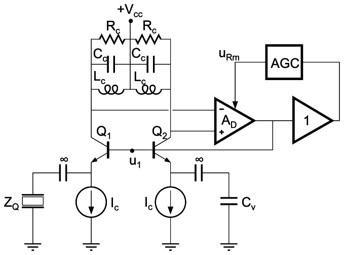
The principle of the balanced bridge oscillator is depicted in Figure 15. Two ideally equal branches form a differential configuration; the input signal u1 is transferred to the emitters of Q1 and Q2 and the emitter currents are voltage-converted at the collectors and fed-back to the input after differential amplification. For a perfect compensation (Cv=C0*), the ideal loop-gain of the oscillator circuit is:
| (25) |
Figure 15.
Schematics of the operation principle of a balanced bridge oscillator configuration.
Assuming no phase shift of the differential amplifier, the zero-phase of the resonator motional branch governs the oscillation phase condition of the circuit. The minimum gain AD for oscillation would be AD = Rm/Rc; therefore, by appropriate selection of Rc a wide loading range could be driven with this type of oscillator. For a better operation, minimizing nonlinearities of the active devices, an AGC can be implemented which, in turn, provides the information about resonator losses.
As in all oscillator configurations the appropriate component selection is a crucial matter for an accurate zero-phase loop condition at the desired phase of the resonator. In this configuration, the use of “diamond transistors” (OTA) [92] can greatly improve the performance of the system. A circuit proposal for a balanced bridge oscillator using OTAs has been introduced elsewhere [29].
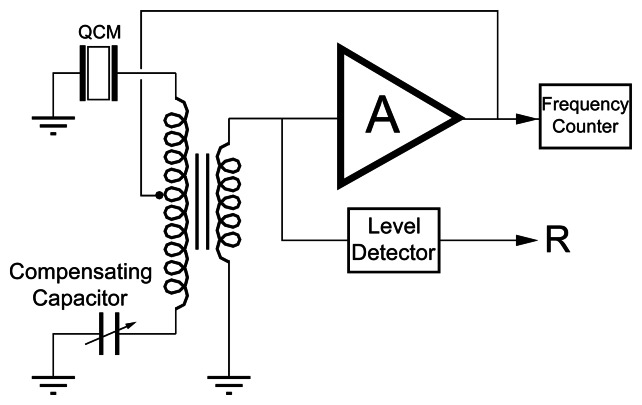
The balanced bridge oscillator uses a capacitor for implementing the parallel capacitance compensation; this type of capacitance compensation can be extended to other type of oscillator configurations by using the circuit shown in Figure 16[96, 97]. The major problem of this technique is the lack of ideality of the transformers and the selection of the capacitance Cv for compensating the parallel capacitance, i.e., the calibration of the parallel capacitance compensation.
Figure 16.
Schematic circuit for parallel capacitance compensation based on a three-winding transformer.
A comprehensive overview of different oscillator configurations proposed for driven QCM sensors under heavy loading condition has been presented. As it can be noticed emitter coupled oscillators designed, in principle, for a zero-phase oscillating condition of the resonator, were finally adjusted to a resonator phase of around -40°. The frequency shift and damping monitoring, together with the knowledge of the phase at which the resonator is operating in the oscillator, allow recovering the true MSRF and motional resistance if previous characterization of the unperturbed resonator and careful calibration of the oscillator circuit are made [75]. For that, expensive instrumentation, like impedance or network analyzers, could be necessary. Thus, the advantage of the simplicity of oscillator circuits is, after all, broken.
Bridge and active bridge oscillators are simple and accurate enough to be successfully used to drive heavy loaded resonators in a wide dynamic range of loads, but the accuracy of the tracking frequency and resonator loss information depends strongly on the ideal characteristics of the components and, even more importantly, on the fidelity with which the parallel capacitance is tuned out with a parallel inductance, which is not an easy task and is only valid at a certain frequency not known “a priori”. Apparently balanced bridge oscillators have been proposed as excellent alternative and, appropriately designed, could compensate the parallel capacitance in a wide range of frequencies and then tracking the MSRF and the resonator loss Rm more accurately than the rest of the configurations. However, until now no oscillator configuration has been described able to accurately drive the resonator at MSRF on a wide range of loads. For this goal oscillator-like operating circuits based on phase locked loop techniques (next section) could be a good solution.
Fortunately, there are many applications in which oscillators, although not rigorously working at MSRF, are the best option. Effectively, for applications in which the resonator loss and the parallel capacitance are maintained relatively constant during experiment, the frequency shift of the resonator sensor, which is the parameter of interest, is practically independent on the resonator phase under oscillating conditions. These applications as in most of piezoelectric biosensors and in some electrochemical applications like ac-electrogravimetry, among others, can be appropriately monitored with oscillators described in this section. The relative simplicity and the small size of these circuits allow a very good control of the environmental conditions, what can drastically reduce the noise and improve the stability.
On the other hand, when the resonator losses and parallel capacitance change during experiment, the deviations in the measurements should be carefully evaluated to be conscious of the error propagation in the interpretation of results. In general, oscillators are not a good interface in these cases. Passive measurements based on network or impedance analyzers could be used or, alternatively, simpler and cheaper systems which operate similarly to oscillators but implement a passive interrogation of the sensor, allowing an easy and accurate calibration of the system. These configurations are based on lock-in techniques, and will be described in the next section.
4.4. Lock-in Techniques
These techniques aim at the simplicity of oscillators while overcoming their limitations. From the previous analysis on oscillators, it can be noticed that their limitations come from the fact that the oscillation depends on a loop condition in which the sensor is integrated, then the resonator phase condition for oscillation is the one necessary to compensate the phase response of the rest of the components of the loop. Any no-ideality in the phase-frequency response of the external circuit, mainly due to active devices, is transferred to the sensor which changes the phase and then the frequency in order to comply with the loop oscillation condition. It has been shown how a good selection of components and a zero-phase condition of the external circuit to the sensor under parallel capacitance compensation can provide good results. Then, the problem of dependence of the no-idealities of the active components can be solved if the resonator is passively interrogated with an external oscillator whose frequency locks the MSRF. To this aim two techniques have been proposed: a) the oscillator locks the zero-phase frequency of the resonators under parallel capacitance compensation conditions and b) the oscillator finds or locks the maximum conductance frequency of the sensor. Next some different approaches for these techniques will be introduced.
4.4.1. Phase-locked loop techniques with parallel capacitance compensation
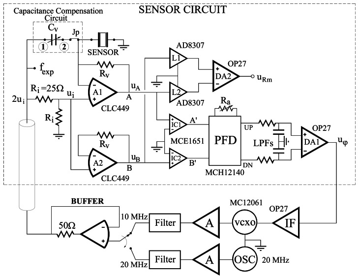
In these techniques an external voltage-controlled oscillator (VCO) locks at the zero-phase frequency of the motional branch of the sensor. For that aim this technique must simultaneously accomplish accurate parallel capacitance compensation which should be controlled by an easy calibration procedure. A circuit implementing a phase locked loop (PLL) technique with parallel capacitance compensation is shown in Figure 17[77].
Figure 17.
Circuit for parallel capacitance compensation based on a phase-locked loop technique.
Similar previous approaches do not maintain one face of the resonator connected to real ground, and more complex calibration procedures are required to assure that the system locks at MSRF and that the parallel capacitance is accurately compensated [98-100]. On the contrary, the system in Figure 17 allows a very easy and effective calibration without the need of additional expensive instrumentation.
The basic operation of the circuit can be summarized a follows. When the current through the capacitor Cv equals the current through the parallel capacitance of the sensor, only the motional arm of the sensor influences the voltage uA. Because the PLL maintains the phases of the signals at points A and B equal, the MSRF of the sensor is continuously locked by the system. For that appropriate calibration must be performed in an easy way as explained elsewhere [77].
An improved version of the system previously described is depicted in Figure 18[101].
Figure 18.
Schematics of a practical realization of PLL based system for sensor MSRF tracking with automatic parallel capacitance compensation.
The aim of the system is to perform a continuous parallel capacitance compensation which is very interesting since it permits the monitoring of an additional important parameter in some applications. The concept behind the design was introduced elsewhere [102, 103]; that is, by simultaneous exciting the quartz crystal at two frequencies, and assuming linear behavior of the resonator at the driving level of the signals, the compensation of the parallel capacitance C0* is automatically and simultaneously made with the locking of the MSRF of the sensor. This is accomplished with two PLL working at different frequencies, one is an auxiliary frequency used for testing the value of the parallel capacitance and the other is the sweeping frequency around the resonance of the sensor. Details of the calibration steps with a more detailed explanation of the system operation have been introduced elsewhere [29, 101].
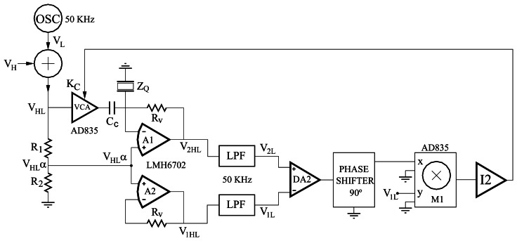
A different parallel compensation concept is used in references [102, 103] at low frequencies far from resonance, where only capacitive behavior of the sensor is expected, for instance 50 KHz. In this approach the parallel compensation detects a null voltage instead of a phase condition; the schema, only the capacitance compensation loop, is depicted in Figure 19. Effectively, for stable operation of the loop a null voltage is necessary at the input of the integrator I2. This is only possible for a zero-voltage at the input of the multiplier M1, which occurs when the amplifier A1 acts as a follower, it is to say, when the parallel capacitance is compensated.
Figure 19.
Parallel capacitance compensation technique using null-voltage detection instead of null-phase detection.
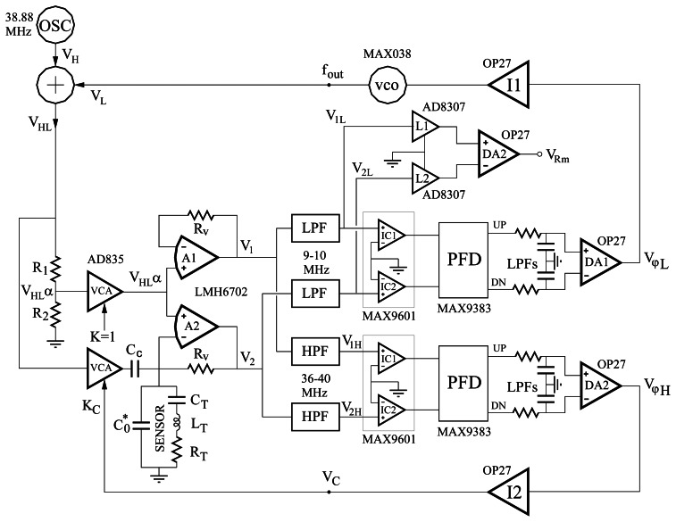
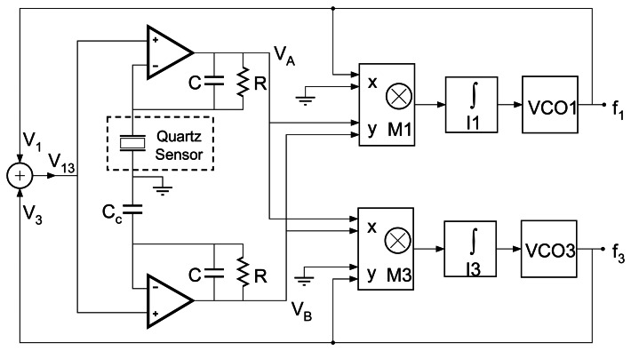
By applying the same concept of simultaneously exciting the sensor at different frequencies, different harmonics can be monitored at the same time. Recently a very nice and simple design has been introduced for a dual-harmonic oscillator-like operating circuit [104] (Figure 20).
Figure 20.
Dual-harmonic interface system for QCM sensors based on phase-locked loop technique.
The schematic depicted in Figure 20 uses a phase detection based on multipliers, like in [102, 103], and includes parallel capacitance compensation as well, although not automatic in this case for simplicity purposes.
The key concept of the PLL techniques is the accurate compensation of the parallel capacitance. An alternative technique is to lock at the frequency at which the conductance of the sensor reaches a maximum, which coincides with the MSRF in most of cases [15]. Because the conductance of the sensor is not influenced by the parallel capacitance, this technique avoids the necessity of its compensation.
4.4.2. Lock-in Techniques at Maximum Conductance Frequency
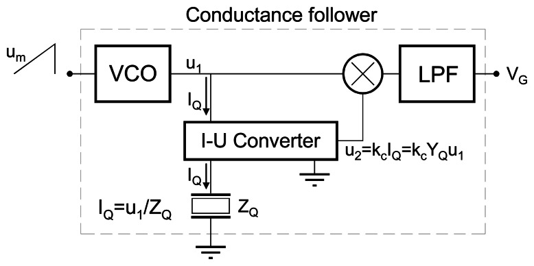
The schematic concept of these techniques is depicted in Figure 21. The sensor is passively interrogated by a signal whose frequency sweeps the resonance frequency range. The current through the sensor is voltage-converted and multiplied with the interrogating signal. The low frequency component, VG, at the output of the multiplier is proportional to the conductance.
Figure 21.
Schematics of the basic operational concept of the lock-in techniques at maximum conductance.
The problem now is how to detect or lock at the maximum of this signal. Some efforts have been addressed to this aim. Nakamoto and Kobayashi [105] proposed a circuit based on this concept which used a peak detector for detecting the maximum of this signal; at the peak detection additional digital circuitry allowed the acquisition of the corresponding voltage at the input of the VCO and the value of the voltage VGmax. This sweeping was repeated cyclically around each second. The acquired values of the VCO input voltage and the conductance voltage VG at the peak give information about the frequency and resonator loss. In order to obtain enough frequency resolution, a voltage-controlled crystal oscillator (VCXO) was used which greatly limits the dynamic range of the system (see next section). The design worked fine for high Q sensors but the flatness of the conductance peak for low Q resonators made the detection of the conductance peak difficult and the accuracy of the measurements to decrease.
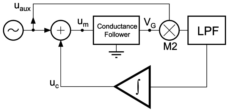
Recently, a method for continuously locking at the maximum conductance frequency has been introduced by Jakoby et al [106]. In this method the block depicted in Figure 21 is included inside another loop as indicated in Figure 22. According to this schema, the output signal of the VCO is frequency modulated by two signals: one coming from the integrator, uc, and another auxiliary low frequency signal coming from an external function generator, uaux, for example a sinusoidal signal. The signal from the integrator determines the central frequency, namely the carrier at the output of the VCO in Figure 21, and the low frequency signal provides a carrier frequency modulation with a deviation which depends on the signal amplitude. Therefore, this system implements a frequency modulation whose carrier frequency shifts until the maximum conductance frequency is locked [29, 106].
Figure 22.
Automatic lock-in technique at maximum conductance.
In this technique the signal that interrogates the sensor is a frequency modulated signal, therefore the information on the maximum conductance frequency is provided through the output voltage of the integrator under locking conditions; in this case the frequency resolution depends on the resolution in measuring the voltage, which depends on the frequency-voltage response of the VCO; for high resolution, narrow frequency sweeping ranges must be covered with wide voltage ranges, then a VCXO can be a good solution, although the dynamic frequency range is drastically reduced.
4.5. Interface Circuits for Fast QCM Applications
Fast QCM can be defined as a QCM in which the frequency changes to be monitored can occur at a very high rate, for instance 1000 times per second. It means that the characteristic resonant frequency of the resonator sensor is changing at rate of 1000 times per second. At this moment no interface circuit, with exception of oscillators, is able to monitor the frequency of the resonator sensor at such rate; PLL techniques, as those mentioned above, could be an alternative solution providing a voltage directly proportional to the frequency change. However, to have enough frequency-voltage sensitivity very narrow locking ranges to be covered with wide voltage ranges would be necessary; however, it would reduce the dynamic frequency range of the system and therefore, special PLL techniques have to be developed for this aim.
The fact that oscillators are able to track the high-rate frequency shifts of the resonator does not solve the problem, because these very quickly changing frequency shifts at high central frequencies are not easy to measure with enough resolution and accuracy and, therefore, special techniques must be developed for monitoring them. A system proposed for solving this problem in ac-electrogravimetry applications has been introduced elsewhere [55, 107-109] whose block diagram is shown in Figure 23.
Figure 23.
Schematics of an interface electronic system for fast QCM operation. Adapted from [55].
The basic operation of the system can be summarized as follows. The main loop is a PLL which locks to the frequency of the oscillator in the electrochemical quartz crystal microbalance (EQCM); therefore the voltage at the input of the voltage crystal controlled oscillator (VCXO) is the demodulated voltage, proportional to the frequency shifts which occur during the experiment. For improving the resolution a VCXO instead of a typical voltage controlled oscillator (VCO) is used but it reduces the lock range of the main loop. To solve this problem, an external second loop, which includes a numerical control oscillator (NCO) controlled by a digital system (field programmable gate array-FPGA), makes a feed-forward correction extending the operating range of the main loop. In other words the NCO performs the coarse tuning meanwhile the main loop performs the fine tracking of the PLL.
The proposed system has been successfully implemented with sensitivity higher than 15mV/Hz and with flat amplitude-frequency and phase-frequency responses in a bandwidth bigger than 2,5KHz. It means that the system can follow frequency changes at rate as high as 2,5KHz with negligible amplitude and phase distortion. The system has been also implemented successfully in the characterization of electroactive polymers demonstrating that high rate responses in conductive polymers are possible [108, 109].
5. Conclusions
The problem associated with interface circuits for QCM sensors reveals that an optimal device for sensor characterization does not exist at present. The systems that better characterize the sensor are those which passively interrogate the quartz resonator so that the sensor is measured in isolation. However, these systems based on impedance analyzers or decay/impulse excitation methods include expensive equipment and do not fulfill the autonomy normally required for portable applications and are not appropriate for fast QCM measurements. On the other hand, those systems which fulfill the simplicity, autonomy and low price requirements appropriate for sensor applications have less accuracy in the determination of sensor parameters; mainly, because the external circuitry influences the sensor response which is not measured in isolation. This problem becomes more critical due to the difficulty of calibrating the response of the external circuitry in typical oscillators. Thus, the monitored parameters can not be accurately associated with a certain phase of the sensor.
Consequently, when using an oscillator to measure the frequency shift, it is necessary to consider the change in the motional resistance as well. If the motional resistance and/or the parallel capacitance change during experiment, the frequency shift monitored with the oscillator could not be equal to the MSRF shift. Thus the associated physical parameters extracted from the monitored frequency shift could include an error which is necessary to consider.
New techniques are being implemented which reasonably combine the accuracy of expensive instrumentation and the simplicity of oscillators. The overview of these lock-in techniques has shown that they should be considered as a good alternative in the future.
Acknowledgments
The authors are grateful to the Spanish Ministry of Science and Technology for financially supporting this research under contract reference: AGL2006-12147/ALI.
References and Notes
- 1.Czanderna A.W., Lu C. In: Applications of Piezoelectric Quartz Crystal Microbalances. Czanderna A.W., Lu C., editors. Volume 7. Elsevier; Amsterdam: 1984. pp. 1–393. [Google Scholar]
- 2.Konash P.L., Bastiaans G.J. Piezoelectric crystals as detectors for liquid chromatography. Analytical Chemistry. 1980;52:1929–1931. doi: 10.1021/ac50062a033. [DOI] [Google Scholar]
- 3.Kanazawa K.K., Gordon J.G., II The oscillation frequency of a quartz resonator in contact with a liquid. Analytica Chimica Acta. 1985;175:99–105. doi: 10.1016/S0003-2670(00)82721-X. [DOI] [Google Scholar]
- 4.Reed C.E., Kanazawa K.K., Kaufman J.H. Physical description of a viscoelastically loaded AT-cut quartz resonator. Journal of Applied Physics. 1990;68(5):1993–2001. doi: 10.1063/1.346548. [DOI] [Google Scholar]
- 5.Kurosawa S., Tawara E. Oscillating frequency of piezoelectric quartz crystal in solutions. Analytica Chimica Acta. 1990;230(1):41–49. doi: 10.1016/S0003-2670(00)82759-2. [DOI] [Google Scholar]
- 6.Schumacher R. The quartz microbalance: a novel approach to the in-situ investigation of interfacial phenomena at the solid/liquid junction. Angew. Chem. Int. Ed. In English. 1990;29(4):329–343. doi: 10.1002/anie.199003293. [DOI] [Google Scholar]
- 7.Davis K. A., Leary T.R. Continuous liquid-phase piezoelectric biosensor for kinetic immunoassays. Anal. Chem. 1989;61:1227–1230. doi: 10.1021/ac00186a010. PubMed 2757206. [DOI] [PubMed] [Google Scholar]
- 8.Shana Z.A., Radtke D.E. Theory and applications of quartz resonator as a sensor for viscous-liquids. Analytica Chimica Acta. 1990;231(2):317–320. doi: 10.1016/S0003-2670(00)86434-X. [DOI] [Google Scholar]
- 9.Behling C., Lucklum R., Hauptmann P. Possibilities and limitations in quantitative determination of polymer shear parameters by TSM resonators. Sensors and Actuators A. 1997;61:260–266. [Google Scholar]
- 10.Behling C., Lucklum R., Hauptmann P. The non-gravimetric quartz crystal resonator response and its application for polymer shear moduli determination. Meas. Sci. Technol. 1998;9:1886–1893. doi: 10.1088/0957-0233/9/11/014. [DOI] [Google Scholar]
- 11.Lucklum R., Behling C., Hauptmann P. Role of mass accumulation and viscoelastic film properties for the response of acoustic-wave-based chemical sensors. Anal. Chem. 1999;71:2488–2496. doi: 10.1021/ac981245l. [DOI] [PubMed] [Google Scholar]
- 12.Jiménez Y., Otero M., Arnau A. In: Piezoelectric Transducer and Applications. 2nd Ed. Arnau A., editor. Springer-VerlagBerlin; Heidelberg: 2008. [Google Scholar]
- 13.Martin S.J., Granstaff V. E., Frye G.C. Characterization of a quartz crystal microbalance with simultaneous mass and liquid loading. Anal. Chem. 1991;63:2272–2281. doi: 10.1021/ac00020a015. [DOI] [Google Scholar]
- 14.Lee S.W., Hinsberg W.D., Kanazawa K.K. Determination of the viscoelastic properties of polymer films using a compensated phase-locked oscillator circuit. Anal. Chem. 2002;74(1):125–131. doi: 10.1021/ac0108358. PubMed 11795780. [DOI] [PubMed] [Google Scholar]
- 15.Arnau A., Jiménez Y., Sogorb T. Thickness shear mode quartz crystal resonators in viscoelastic fluid media. J. Appl. Phys. 2000;88:4498–4506. doi: 10.1063/1.1309122. [DOI] [Google Scholar]
- 16.Gabrielli C., Perrot H., Rose D., Rubin A., Pham M.C., Piro B. New frequency/voltage converters for ac-electrogravimetric measurements based on fast quartz crystal microbalance. Review Scientific Instruments. 2007;78:6. doi: 10.1063/1.2751093. [DOI] [PubMed] [Google Scholar]
- 17.Janshoff A., Galla H.-J., Steinem C. Piezoelectric mass-sensing devices as biosensors-an alternative to optical biosensors? Angew. Chem. Int. Ed. 2000;39:4004–4032. doi: 10.1002/1521-3773(20001117)39:22<4004::aid-anie4004>3.0.co;2-2. [DOI] [PubMed] [Google Scholar]
- 18.A survey of the 2001 to 2005 quartz crystal microbalance biosensor literature: applications of acoustic physics to the analysis of biomolecular interactions. Journal of Molecular Recognition. 2007;20(3):154–184. doi: 10.1002/jmr.826. PubMed 17582799. [DOI] [PubMed] [Google Scholar]
- 19.Camesano T.A., Liu Y.T., Datta M. Measuring bacterial adhesion at environmental interfaces with single-cell and single-molecule techniques. Advances in Water Resources. 2007;30:1470–1491. [Google Scholar]
- 20.Lazcka O., Del Campo F.J., Muñoz F.X. Pathogen detection: A perspective of traditional methods and biosensors. Biosensors & Bioelectronics. 2007;22(7):1205–1217. doi: 10.1016/j.bios.2006.06.036. [DOI] [PubMed] [Google Scholar]
- 21.Hug T.S. Biophysical methods fro monitoring cell-substrate interactions in drug discovery. Assay and Drug Development Technologies. 2003;1(3):479–488. doi: 10.1089/154065803322163795. PubMed 15090185. [DOI] [PubMed] [Google Scholar]
- 22.Dickert FL., Lieberzeit P., Hayden O. Sensor strategies for micro-organism detection – from physical principles to imprinting procedures. Analytical and Bioanalytical Chemistry. 2003;377(3):540–549. doi: 10.1007/s00216-003-2060-5. PubMed 12920496. [DOI] [PubMed] [Google Scholar]
- 23.Marx KA. Quartz crystal microbalance: A useful tool for studying thin polymer films and complex biomolecular systems at the solution-surface interface. Biomacromolecules. 2003;4(5):1099–1120. doi: 10.1021/bm020116i. PubMed 12959572. [DOI] [PubMed] [Google Scholar]
- 24.Fahnrich KA., Pravda M., Guilbault GG. Immunochemical detection of polycyclic aromatic hydrocarbons (PAHs) Analytical Letters. 2002;35(8):1269–1300. doi: 10.1081/AL-120006666. [DOI] [Google Scholar]
- 25.Wegener J., Janshoff A., Steinem C. The quartz crystal microbalance as a novel means to study cell-substrate interactions in situ. Cell Biochemistry and Biophysics. 2001;34(1):121–151. doi: 10.1385/CBB:34:1:121. PubMed 11394439. [DOI] [PubMed] [Google Scholar]
- 26.O'Sullivan CK., Guilbault G.G. Commercial quartz crystal microbalances – theory and applications. Biosensors & Bioelectronics. 1999;14:663–670. [Google Scholar]
- 27.O'Sullivan CK., Vaughan R., Guilbault GG. Piezoelectric immunosensors – theory and applications. Analytical Letters. 1999;32(12):2353–2377. [Google Scholar]
- 28.Bizet K., Grabielli C., Perrot H. Biosensors based on piezoelectric transducers. Analusis EurJAC. 1999;27:609–616. [Google Scholar]
- 29.Arnau A., Ferrari V., Soares D., Perrot H. In: Piezoelectric Transducers and Applications. 2nd Ed. Arnau A., editor. Springer-Verlag; Berlin Heidelberg: 2008. [Google Scholar]
- 30.Ni R., Zhang XB., Liu W., Shen GL., Yu RQ. Piezoelectric quartz crystal sensor array with optimized oscillator circuit for analysis of organic vapours mixtures. Sensors and Actuators B. 2003;88:198–204. [Google Scholar]
- 31.Lucklum R., Soares D., Kanazawa K.K. In: Piezoelectric Transducers and Applications. 2nd Ed. Arnau A., editor. Springer-Verlag; Berlin-Heidelberg: 2008. p. 63. Chapter 3. in press. [Google Scholar]
- 32.Arnau A., Jiménez Y., Sogorb T. An extended Butterworth-Van Dyke model for QCM applications in viscoelastic fluid media. IEEE Trans. Ultrason, Ferroelect. Freq. Contr. 2001;48:1367–1382. doi: 10.1109/58.949746. [DOI] [PubMed] [Google Scholar]
- 33.Barnes C. Development of quartz crystal-oscillators for under liquid sensing. Sensors and Actuators A-Physical. 1991;29(1):59–69. doi: 10.1016/0924-4247(91)80032-K. [DOI] [Google Scholar]
- 34.IEC Standard, publication 444-1 Measurement of quartz crystal unit parameters by zero phase technique in a pi-network (Part 1) International Electrotechnical Commission. 1986 [Google Scholar]
- 35.Arnau A., Sogorb T., Jiménez Y. A new method for continuous monitoring of series resonance frequency and simple determination of motional impedance parameters for loaded quartz crystal resonators. IEEE Trans. Ultrason. Ferroelect. Freq. Contr. 2001;48:617–623. doi: 10.1109/58.911746. [DOI] [PubMed] [Google Scholar]
- 36.Cady W.G. Piezoelectricity: an introduction to the theory and applications of electromechanical phenomena in crystals. Dover Publication, Inc.; New York: 1964. [Google Scholar]
- 37.Buttry D.A., Ward D.W. Measurements of interfacial processes at electrode surfaces with the electrochemical quartz crystal microbalance. Chem. Rev. 1992;92(6):1355–1379. doi: 10.1021/cr00014a006. [DOI] [Google Scholar]
- 38.Jiménez Y., Fernández R., Torres R., Arnau A. A contribution to solve the problem of coating properties extraction in quartz crystal microbalance applications. IEEE Trans. Ultrason. Ferroelect. Freq. Contr. 2006;53(5):1057–1072. doi: 10.1109/TUFFC.2006.1632695. [DOI] [PubMed] [Google Scholar]
- 39.Zhang C., Vetelino J.F. Bulk acoustic wave sensors for sensing measurand-induced electrical property changes in solutions. IEEE Trans. Ultrason. Ferroelect. Freq. Contr. 2001;48(3):773–778. doi: 10.1109/58.920710. [DOI] [PubMed] [Google Scholar]
- 40.Ferrari V., Lucklum R. In: Piezoelectric Transducers and Applications. 2nd Ed. Arnau A., editor. Springer-Verlag; Berlin-Heidelberg: 2008. p. 39. Chapter 2. in press. [Google Scholar]
- 41.Lucklum R., Hauptmann P. Determination of polymer shear modulus with quartz crystal resonators. Faraday Discussions. 1997;107:123–140. doi: 10.1039/a703127k. [DOI] [Google Scholar]
- 42.Montoya A., Ocampo A., March C. In: Piezoelectric Transducers and Applications. 2nd Ed. Arnau A., editor. Springer-Verlag; Berlin-Heidelberg: 2008. p. 289. Chapter 12. in press. [Google Scholar]
- 43.Cernosek R. W., Martin S. J., Hillman A. R., Bandey H.L. Comparison of lumped-element and transmission-line models for thickness-shear-mode quartz resonator sensors. IEEE Trans. Ultrason. Ferroelect. Freq. Contr. 1998;45:1399–1407. doi: 10.1109/58.726468. [DOI] [Google Scholar]
- 44.Johannsmann D., Mathauer K. Viscoelastic properties of thin films probed with a quartz crystal resonator. Physical Review B. 1992;46(12):7808–7815. doi: 10.1103/PhysRevB.46.7808. [DOI] [PubMed] [Google Scholar]
- 45.Yang M., Thompson M. Interfacial properties and the response of the Thickness-Shear-Mode acoustic wave sensor in Liquids. Langmuir. 1993;9:802–811. doi: 10.1021/la00027a033. [DOI] [Google Scholar]
- 46.Yang M., Thompson M. Acoustic network analysis and equivalent circuit simulation of the Thickness-Shear-Mode acoustic wave sensor in liquid phase. Analytica Chimica Acta. 1993;282:505–515. doi: 10.1016/0003-2670(93)80114-Z. [DOI] [Google Scholar]
- 47.Noël M., Topart P.A. High frequency impedance analysis of quartz microbalances I. General considerations. Analytical Chemistry. 1994;66(4):484–491. [Google Scholar]
- 48.Eichelbaum F., Borngräber R., Schröder J., Lucklum R., Hauptmann P. Interface circuits for quartz crystal microbalance sensors. Rev. Sci. Instrum. 1999;70:2537–2545. doi: 10.1063/1.1149788. [DOI] [Google Scholar]
- 49.Schmid M., Benes E., Sedlaczek R. A computer-controlled system for the measurement of complete admittance spectra of piezoelectric resonators. Meas. Sci. Technol. 1990;1:970–975. [Google Scholar]
- 50.Schröder J., Borngräber R., Lucklum R., Hauptmann P. Network analysis based interface electronics for quartz crystal microbalance. Review Scientific Instruments. 2001;72:2750–2755. [Google Scholar]
- 51.Schröder J., Borngräber R., Eichelbaum F., Hauptmann P. Advanced interface electronics and methods for QCM. Sensors and Actuators A. 2002;97-98:543–547. [Google Scholar]
- 52.Auge J., Dierks K., Eichelbaum F., Hauptmann P. High-speed multi-parameter data acquisition and web-based remote access to resonant sensors and sensor arrays. Sensors and Actuators B. 2003;95:32–38. [Google Scholar]
- 53.Doerner S., Schneider T., Schröder J., Hauptmann P. Universal impedance spectrum analyzer for sensor applications. Proceedings of IEEE Sensors. 2003;1:596–594. [Google Scholar]
- 54.Schnitzer R., Reiter C., Harms KC., Benes E., Gröschl M. A general-purpose online measurement system for resonant BAW sensors. IEEE Sensors Journal. 2006;6(5):1314–1322. doi: 10.1109/JSEN.2006.877977. [DOI] [Google Scholar]
- 55.Torres R., Arnau A., Perrot H., García J., Grabielli C. Analog-Digital Phase-Locked Loop for alternating current quartz electrogravimetry. Electronics Letters. 2006;42:1272–1273. [Google Scholar]
- 56.Kurosawa S., Kitajima H., Ogawa Y., Muratsugu M., Nemoto E., Kamo N. Resonant Frequency of a Piezoelectric Quartz Crystal in Contact with Solutions. Analytica Chimica Acta. 1993;274:209–217. doi: 10.1016/0003-2670(93)80467-Y. [DOI] [Google Scholar]
- 57.Calvo E.J., Etchenique R., Barlett P.N., Singhal K., Santamaría C. Quartz crystal impedance studies at 10 MHz of viscoelastic liquids and films. Faraday Discuss. 1997;107:141–157. doi: 10.1039/a703551i. [DOI] [Google Scholar]
- 58.Kankare J., Loikas K., Salomaki M. Method for measuring the losses and loading of a quartz crystal microbalance. Analytical Chemistry. 2006;78:1875–1882. doi: 10.1021/ac051908g. PubMed 16536423. [DOI] [PubMed] [Google Scholar]
- 59.Rodahl M., Kasemo B. A simple setup to simultaneously measure the resonant frequency and the absolute dissipation factor of a quartz crystal microbalance. Rev. Sci. Instrum. 1996;67:3238–3241. doi: 10.1063/1.1147494. [DOI] [Google Scholar]
- 60.Rodahl M., Kasemo B. Frequency and dissipation-factor responses to localized liquid deposits on a QCM electrode. Sensors and Actuators B. 1996;37:111–116. doi: 10.1016/S0925-4005(97)80077-9. [DOI] [Google Scholar]
- 61.Rodahl M., Hook F., Kasemo B. QCM operation in liquids: An explanation of measured variations in frequency and Q factor with liquid conductivity. Anal. Chem. 1996;68:2219–2227. doi: 10.1021/ac951203m. [DOI] [PubMed] [Google Scholar]
- 62.Edwardsson M., Rodalh M., Kasemo B., Hook F. A dual-frequency QCM-D setup operating at elevated oscillation amplitudes. Anal. Chem. 2006;77:4918–4926. doi: 10.1021/ac050116j. [DOI] [PubMed] [Google Scholar]
- 63.Parzen B., Ballato A. Design of crystal and other harmonic oscillators. John Wiley & Sons; New York: 1983. p. 454. [Google Scholar]
- 64.Frerking M.E. Crystal oscillator design and temperature compensation. Van Nostrand Reinhold; New York: 1978. p. 240. [Google Scholar]
- 65.Ehahoun H., Gabrielli C., Keddam M., Perrot H., Rousseau P. Performances and limits of a parallel oscillator for electrochemical quartz crystal microbalances. Anal Chem. 2002;74:1119–1127. doi: 10.1021/ac010883s. PubMed 11924973. [DOI] [PubMed] [Google Scholar]
- 66.Barnes C. Some new concepts on factors influencing the operational frequency of liquid-immersed quartz microbalances. Sensors and Actuators A-Physical. 1992;30(3):197–202. doi: 10.1016/0924-4247(92)80120-R. [DOI] [Google Scholar]
- 67.Tiean Z., Nie L.H. On equivalent-circuits of piezoelectric quartz crystals in a liquid and liquid properties I. Theoretical derivation of equivalent-circuit and effects of density and viscosity of liquids. Journal of Electroanalytical Chemistry. 1990;293:1–18. [Google Scholar]
- 68.Auge J., Hauptmann P., Eichelbaum F., Rösler S. Quartz crystal microbalance sensor in liquids. Sensor and Actuators B. 1994;18-19:518–522. [Google Scholar]
- 69.Bottom V.E. Introduction to Quartz Crystal Unit Design. Van Nostrand; New York: 1982. [Google Scholar]
- 70.Hayward G. Viscous interaction with oscillating piezoelectric quartz crystals. Analytica Chimica Acta. 1992;264(1):23–30. doi: 10.1016/0003-2670(92)85292-E. [DOI] [Google Scholar]
- 71.Hayward G., Chu G.Z. Simultaneous measurement of mass and viscosity using piezoelectric quartz crystals in liquid-media. Analytica Chimica Acta. 1994;288(3):179–185. doi: 10.1016/0003-2670(94)80131-2. [DOI] [Google Scholar]
- 72.Wessendorf K.O. The lever oscillator for use in high resistance resonator applications. Proceedings of the 1993 IEEE International Frequency Control Symposium. 1993:711–717. [Google Scholar]
- 73.Chagnard C., Gilbert P., Watkins A. N., Beeler T., Paul D.W. An electronic oscillator with automatic gain control: EQCM applications. Sensors and Actuators B. 1996;32:129–136. doi: 10.1016/0925-4005(96)80121-3. [DOI] [Google Scholar]
- 74.Paul D.W., Beeler T.L. Piezoelectric sensor Q-loss compensation. US Patent No. 4788466. 1998
- 75.Borngräber R., Schröder J., Lucklum R., Hauptmann P. Is an oscillator-based measurement adequate in a liquid environment? IEEE Trans. Ultrason. Ferroelect. Freq. Contr. 2002;49(9):1254–1259. doi: 10.1109/TUFFC.2002.1041542. [DOI] [PubMed] [Google Scholar]
- 76.Martin S. J., Spates J. J., Wessendorf K. O., Schneider T. W., Huber R. J. Resonator/oscillator response to liquid loading. Anal. Chem. 1997;69:2050–2054. doi: 10.1021/ac961194x. [DOI] [PubMed] [Google Scholar]
- 77.Arnau A., Sogorb T., Jiménez Y. Circuit for continuous motional series resonant frequency and motional resistance monitoring of quartz crystal resonators by parallel capacitance compensation. Rev. Sci. Instrum. 2002;73(7):2724–2737. doi: 10.1063/1.1484254. [DOI] [Google Scholar]
- 78.Rodriguez-Pardo L., Fariña J., Gabrielli C., Perrot H., Brendel R. Resolution in quartz oscillator circuits for high sensitivity microbalance sensors in damping media. Sensors and Actuators B. 2004;103:318–324. doi: 10.1016/j.snb.2004.04.060. [DOI] [Google Scholar]
- 79.Rodriguez-Pardo L., Fariña J., Gabrielli C., Perrot H., Brendel R. Sensitivity, noise, and resolution in QCM sensors in liquid media. IEEE Sensors Journal. 2005;5(6):1251–1257. doi: 10.1109/JSEN.2005.859257. [DOI] [Google Scholar]
- 80.Rodriguez-Pardo L., Fariña J., Gabrielli C., Perrot H., Brendel R. Quartz crystal oscillator circuit for high resolution microgravimetric sensors. Electronics Letters. 2006;42(18):1065–1067. doi: 10.1049/el:20061854. [DOI] [Google Scholar]
- 81.Soares D. A quartz microbalance with the capability of viscoelasticity measurements for in-situ electrochemical investigations. Meas. Sci. Technol. 1993;4:549–553. [Google Scholar]
- 82.Fruböse C., Doblhofer K., Soares D. Impedance analysis of the quartz micro-balance signal. Ber. Bunsenges. Phys. Chem. 1993;97:475–478. [Google Scholar]
- 83.Wessendorf K.O. Oscillator circuit for use with high loss quartz resonator sensors. US Patent No. 5416448. 1995
- 84.Wessendorf K.O. The active bridge oscillator. Proceeding of IEEE International Frequency Control Symposium. 1998:361–369. [Google Scholar]
- 85.Wessendorf K.O. The active-bridge oscillator for use with liquid loaded QCM sensors. Proceedings of IEEE International Frequency Control Symposium and PDA Exhibition. 2001:400–407. [Google Scholar]
- 86.Benes E., Gröschl M., Burger W., Schmid M. Sensors based on piezoelectric resonators. Sensors and Actuators A. 1995;48:1–21. doi: 10.1016/0924-4247(95)00846-2. [DOI] [Google Scholar]
- 87.Benes E., Schmid M., Gröschl M., Berlinger P., Nowotny H., Harms K.C. Solving the cable problem between crystal sensor and electronics by use of a balanced bridge oscillator circuit. Proceedings of the Joint Meeting of the European Frequency and Time Forum and the IEEE International Frequency Control Symposium. 1999;2:1023–1026. [Google Scholar]
- 88.Soares D., Kautek W., Fruböse C., Doblhofer K. The electrochemical quartz crystal microbalance in media of changing viscoelastic properties, and the design and characterization of suitable driver electronics. Ber. Bunsenges. Phys. Chem. 1994;98(2):219–228. [Google Scholar]
- 89.Auge J., Hauptmann P., Hartmann J., Rösler S., Lucklum R. New design from QCM sensors in liquids. Sensors and Actuators B. 1995;24-25:43–48. [Google Scholar]
- 90.Matthys R.J. Crystal oscillator circuits. Revised Ed. Krieger; Malabar: 1992. p. 251. [Google Scholar]
- 91.Data Sheet OPA660 (PDS-1072E) Burr-Brown; Tucson: 1995. [Google Scholar]
- 92.Henn Ch. New ultrahigh-speed circuit techniques with analog ICs. AB-183. Burr-Brown; Tucson: 1995. [Google Scholar]
- 93.Benjaminson A. Balanced feedback oscillators. Proceedings of the 38th Annual Symposium on Frequency Control. 1984:327–333. [Google Scholar]
- 94.Benjaminson A. A crystal oscillator with bidirectional frequency control and feedback ALC. Proceedings of the 40th Annual Symposium on Frequency Control. 1986:344–349. [Google Scholar]
- 95.Wessendorf K.O. Active bridge oscillator. US Patent No. 6169459. 2001
- 96.Geelhood S., Frank C.W., Kanazawa K. Acoustic Wave Sensor Worshop 3. Taos, New Mexico: 2001. [Google Scholar]
- 97.Behrends R., Kaatze U. A high frequency shear wave impedance spectrometer for low viscosity liquids. Meas. Sci. Technol. 2001;12:519–524. doi: 10.1088/0957-0233/12/4/318. [DOI] [Google Scholar]
- 98.Ferrari V., Marioli D., Taroni A. Oscillator circuit configuration for quartz crystal-resonator sensors subject to heavy acoustic load. Electron. Lett. 2000;36(7):610–612. doi: 10.1049/el:20000493. [DOI] [Google Scholar]
- 99.Ferrari V., Marioli D., Taroni A. Improving the accuracy and operating range of quartz microbalance sensors by purposely designed oscillator circuit. IEEE Trans. Instrum. Meas. 2001;50:1119–1122. doi: 10.1109/19.963169. [DOI] [Google Scholar]
- 100.Arnau A., Sogorb T., Jiménez Y. A continuous motional series resonant frequency monitoring circuit and a new method of Determining Butterworth – Van Dyke Parameters of a Quartz Crystal Microbalance in Fluid Media. Review of Scientific Instruments. 2000;71:2563–2571. doi: 10.1063/1.1150649. [DOI] [Google Scholar]
- 101.Arnau A., García J.V., Jiménez Y., Ferrari V., Ferrari M. Improved Electronic Interfaces for Heavy Loaded at Cut Quartz Crystal Microbalance Sensors. Proceedings of Frequency Control Symposium Joint with the 21st European Frequency and Time Forum. IEEE International. 2007:357–362. Extended version submitted to Review of Scientific Instruments. [Google Scholar]
- 102.Ferrari V., Marioli D., Taroni A. ACC oscillator for in-liquid quartz microbalance sensors. Proceedings of IEEE Sensors. 2003;2:849–854. [Google Scholar]
- 103.Ferrari M., Ferrari V., Marioli D., Taroni A., Suman M., Dalcanale E. In-liquid sensing of chemical compounds by QCM sensors coupled with high-accuracy ACC oscillator. IEEE Trans. Instrum. Meas. 2006;55(3):828–834. doi: 10.1109/TIM.2006.873792. [DOI] [Google Scholar]
- 104.Ferrari M., Ferrari V., Kanazawa K.K. Dual-harmonic oscillator for quartz crystal resonator sensors. Solid-State Sensors, Actuators and Microsystems Conference. 2007:241–244. TRANSDUCERS 2007. International; 10-14 June 2007. Extended version in press in Sensors and Actuators A. [Google Scholar]
- 105.Nakamoto T., Kobayasi T. Development of circuit for measuring both Q variation and resonant frequency shift of quartz crystal microbalance. IEEE Trans. Ultrason. Ferroelect. Freq. Contr. 1994;41(6):806–811. doi: 10.1109/58.330261. [DOI] [PubMed] [Google Scholar]
- 106.Jakoby B., Art G., Bastemeijer J. A novel analog readout electronics for microacoustic thickness shear-mode sensors. IEEE Sensors Journal. 2005;5(5):1106–1111. doi: 10.1109/JSEN.2005.844330. [DOI] [Google Scholar]
- 107.Torres R., Arnau A., Perrot H. Electronic System for Experimentation in AC Electrogravimetry II: Implemented Design. Revista EIA. 2007;7:63–73. [Google Scholar]
- 108.Torres R. Ph.D. Thesis. Universidad Politécnica de Valencia; 2007. Instrumental techniques for improving the measurements based on Quartz Crystal Microbalances. [Google Scholar]
- 109.Torres R., García J. V., Arnau A., Perrot H., Gabrielli C. Improved frequency/voltage converters for fast QCM applications. Submitted for review to Scientific Instruments. doi: 10.1063/1.2908430. [DOI] [PubMed] [Google Scholar]


