Abstract
An opto-thermocapillary micromanipulator (OTMm) capable of single-cell manipulation and patterning is presented here. The OTMm uses a near-infrared laser focused on an ITO substrate to induce thermocapillary convection that can trap and transport living cells with forces of up to 40 pN. The OTMm complements other cell-manipulation technologies such as optical tweezers and dielectrophoresis, as it is less dependent upon the optical and electrical properties of the working environment, and can function in many types of cell culture media. The OTMm was used to construct single-cell matrices in two popular hydrogels: PEGDA and agarose. High viability rates were observed in both hydrogels, and cells patterned in agarose spread and migrated during subsequent culturing.
Introduction
Single-cell manipulation and patterning are essential for exploring intercellular interactions1, cell-environment interactions2, 3, and bottom-up assembly in tissue engineering4. Cells can be passively patterned by microfluidic devices5 or micro-structures1, but micro-actuators are more flexible at arranging specific cells into different geometries. Micromanipulators are a popular type of micro-actuator. They have microscopic end-effectors attached to macroscopic actuators, and directly operate on the cells by physical contact6. In order to improve the efficiency and deploy more end-effectors into a microscale working space, the bulky connection to the actuators can be replaced by magnetic forces that enable remote control of the end-effectors7, 8, 9. Although possible, the parallel and independent addressing of multiple magnetic end-effectors uses sophisticated designs and mechanisms7, 8, limiting the overall system throughput.
Compared with direct physical contact, non-contact manipulation does not need to introduce physical structures into the working space, making it possible to manipulate more cells in parallel. One non-contact manipulation tool is acoustic tweezers, which uses standing surface acoustic waves (SAW) generated through on-chip transducers to manipulate single cells or multiple cells in tuneable patterns based on SAW interference patterns10. Technologies exploiting the optical and electrical properties of the cells also have the potential to manipulate cells independently and in parallel11, 12, 13, 14. Multiple methods are available to precisely redirect and split light beams11, 12, allowing optical tweezers to independently address tens of cells at once to form various geometries12. To circumvent the potential damage from the laser illumination15, optical tweezers can be used to manipulate microstructures made of various materials acting as intermediaries16, 17, 18, reducing the cells’ exposure to laser radiation. However, micro-fabricated structures or polymers must to be added into the working medium. Moreover, these microstructures occupy space in the working area, limiting the degree of parallel manipulation.
Dielectrophoresis (DEP) is a widely used electrokinetic non-contact cell-manipulation mechanism. It has been implemented in various microfluidic devices to manipulate or pattern cells19, 20. The direction and the magnitude of the DEP forces for cell manipulation can be adjusted by tuning the conductivity of the working media21. To generate the non-uniform electric fields needed for DEP, electrodes usually need to be micro-fabricated22, 23. Various forms of the DEP devices were reported to manipulate single cells in parallel, such as independently addressed electrodes13, moving pulsed dielectrophoresis24 and optically induced dielectrophoresis (ODEP)14. Among these, ODEP combines the advantages of both light actuation and DEP forces. It uses light to change the conductivity of a device surface, dynamically modulating the electric field inside a liquid medium. This optical addressing of the DEP force makes it possible to manipulate large number of cells independently and in parallel.
When patterning cells, manipulation is desirable in an open chamber, as this makes it easier to harvest the assembled cells or to interface the patterned cells with other technologies. Here we report an opto-thermocapillary micro-manipulator (OTMm) that is capable of manipulating cells in an open chamber. The OTMm is a complementary technology to existing non-contact manipulation tools; it retains the advantages of optical control, but does not rely on optical or electrokinetic forces. Thus, the OTMm is agnostic to the electrical or optical properties of the cell or the media, making it compatible with many liquids, including general culture media or media containing hydrogel pre-polymers.
The OTMm uses optical energy to generate a thermocapillary flow that is used to manipulate cells. The thermocapillary flow arises from the temperature gradient on the surface of optically-induced bubbles, which results from the conversion of optical energy to thermal energy when an indium-tin-oxide (ITO) layer on a glass substrate is illuminated by an infrared laser. Although powered by a laser, the manipulation force is created by the fluidic flow, and the cells are not directly illuminated by the laser.
In a previous report, yeast cells were patterned by the OTMm in agarose hydrogels25. Greater than 90% cell viability was observed, along with cell proliferation. In this report, the potential of the OTMm for mammalian cell patterning is shown by constructing matrices of single NIH/3T3 fibroblasts in polyethylene glycol diacrylate (PEGDA) and agarose hydrogels. Viability tests confirm that cells are safely manipulated using the OTMm.
Mechanism and Characterization
The OTMm setup is shown in Fig. 1. An ITO-coated slide (sheet resistance of 4 to 10 ohms, Delta Technologies), consisting of 1-mm-thick glass topped by a 200-nm-thick ITO layer, was placed under the microscope as the OTMm substrate. A continuous-wave 980-nm laser (Laserlands, 980MD-0.8W-BL) was focused by a plano-convex lens (Newport KPX088) and a 20X objective (Meiji S. Plan M20X, NA: 0.4) onto the substrate, forming a spot with a diameter of 3.87 μm at full-width, half-maximum. The laser was switched on and off by a TTL signal from a function generator (Agilent 33220A). When the laser was on, the intensity was measured to be 414 kW/cm2. In comparison, the operational intensity of the optical tweezers is usually on the order of megawatts per square centimetre.
Fig. 1.
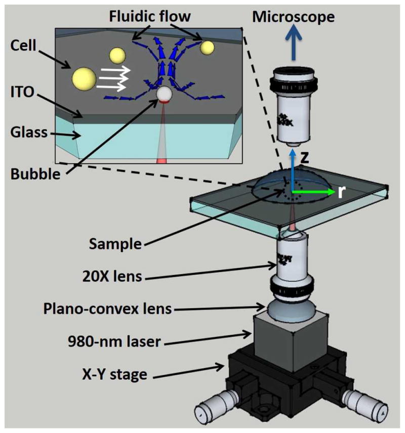
Experimental setup of the opto-thermocapillary micro-manipulator. The inset shows a magnified view of the ITO substrate and the toroidal thermocapillary convection around the opto-thermally generated bubble.
When an air bubble on the substrate of a liquid reservoir is subjected to a temperature gradient normal to the substrate, thermocapillary convection can form around the bubble26 (Fig. S1 in ESI). This thermocapillary flow is used by the OTMm to manipulate cells (Fig. 1, inset). The laser used for the OTMm passes through the glass portion of the slide with negligible absorption, whereupon about 16% of the optical energy is absorbed by the 100-nm-thick ITO layer and converted into heat27. This laser-induced heating is used to generate a bubble in the liquid medium above the ITO layer. The bubble size increases with the pulse width (Fig. S2 in ESI), but the bubbles used in this OTMm system were all less than 1.5 μm in diameter. Once the bubble is created, the temperature gradient on the bubble surface, which is hotter close to the substrate and cooler on the bubble apex far away the substrate, generates a toroidal opto-thermocapillary flow around the bubble (Fig. 1, inset). When the laser is turned off, the opto-thermocapillary flow immediately ceases due to the absence of the temperature gradient, and the bubble quickly dissolves into the medium due to the large Laplace pressure across its surface. In all the experiments discussed here, sufficient time elapses between laser pulses for the bubbles generated by each laser pulse to completely dissolve into the liquid (Fig. S2)
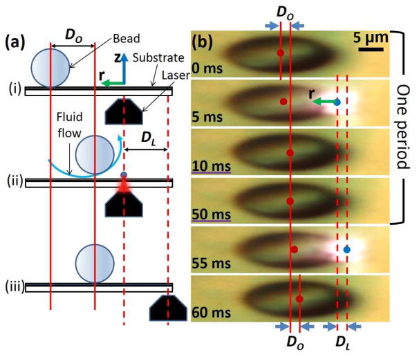
The manipulation mechanism of the OTMm is shown in Fig. 2. Initially, the laser is positioned so that the bead can experience the part of the opto-thermocapillary flow that is closest to the substrate (step i in Fig. 2a). The laser is then briefly turned on, generating a bubble and opto-thermocapillary flow, moving the bead a small distance, DO (step ii in Fig. 2a). At last, the laser turns off and the bubble that was generated dissolves into the liquid. The opto-thermocapillary flow also ceases, along with the motion of the bead. While turned off, the laser moves a displacement distance, DL (step iii in Fig. 2a). This completes a manipulation period; repeating this process can continuously drag the bead in the direction of the laser. Figure 2b captures both the bead and laser displacements during two consecutive laser pulses. The first four images form a complete manipulation period. The bead moved a distance DO during the first period. The bead had no observable motion when laser was off, between the 10 ms and 50 ms frames in Fig. 2b. The bead moved another distance DO in the first part of the second manipulation period (50 to 60 ms). The laser pulse frequency was 20 Hz and the pulse width was 15 μs.
Fig. 2.
(a) A side-view illustration of one manipulation period of the OTMm on a micro-bead. i) The micro-bead position immediately before the laser is turned on. The coordinate axes match the ones shown in Fig. 1. ii) The laser is on, creating a bubble and opto-thermocapillary flow, moving the bead a distance of DO. iii) The laser is off, stopping the flow and the bead movement, while it translates to the next illumination point. (b) Top view of the observed motion of a 20-μm-diameter bead. The bead centroid and laser spot are marked by red dots (
 ) and blue dots (
 ), respectively. The photos have been stretched three times in the x-direction to magnify the displacements. The r-axis is marked in the second frame, and the z-axis is normal to the plane of the page.
If DL = DO is maintained during the manipulation by the OTMm, the bead will follow the laser at a constant velocity. However, if DL > DO due to rapid laser motion, the bead will not be properly positioned in the opto-thermocapillary flow, and will fall behind and stop moving after several manipulation periods. On the other hand, if DL < DO, the bead will move closer to the laser-induced bubble in every period. When the bead is too close to the bubble, it circulates upwards and away from the bubble surface. In this scenario, the manipulation needs to be temporarily suspended. The laser should stop moving until the bead is recirculated back to the thermocapillary flow region that is closest to the substrate; after that, manipulation can resume.
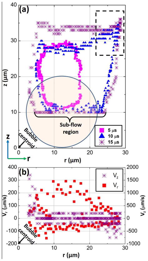
To better quantify the motion of a micro-object subjected to the opto-thermocapillary flow, the movement of a 20-μm-diameter polystyrene bead was tracked while it circulated in the flow generated by laser pulses with a width of 15 μs at a frequency of 20 Hz (Fig. 3a). The bead circulates clockwise in the thermocapillary flow, following the trajectories plotted in Fig. 3a. The perpendicular displacement is extracted from the relative brightness of the bead centroid, as shown in Fig. S3 in the ESI.
Fig. 3.
Side view of a 20-μm-diameter bead motion in the toroidal opto-thermocapillary flow. The bubble was generated at the origin in these graphs. (a) The motion of the bead in an r-z plane, as it circulates around the optothermally-generated bubble, using various laser pulse widths. A circle with 20-μm diameter is drawn on the graph to show the size of the bead. The portion of the overall bead trajectory that is used for manipulation is labeled as the “sub-flow region.” An artifact in the measured bead motion is apparent in the portion of the trajectory bounded by the black dashed lines, and is explained by Fig. S3 in the ESI. (b) The measured horizontal (Vr) and vertical (Vz) instantaneous velocity of the bead as a function of horizontal displacement along the r-direction. The laser pulse frequency was 20 Hz and the pulse width was 15 μs.
Fig. 3b shows the instantaneous velocity of the bead at different locations along the 15 μs trajectory in Fig. 3a. The instantaneous velocity is decoupled into horizontal velocity (Vr) and vertical velocity (Vz) components. A positive Vr refers to bead moving towards the bubbles, while a positive Vz refers to the bead moving upwards and away from the substrate. Vr and Vz have positive and negative values since the bead was circulating around the bubbles. At the section marked by “Sub-flow region” in Fig. 3a, the bead had the highest Vr towards the cavitation bubble and a negligible Vz (Fig.3b). This is the region of the thermocapillary flow used for the OTMm manipulation. If the bead was too close to the bubbles (r ≤ 5 μm in Fig. 3a), which occurs when DL < DO, it entered a region with high Vz moving upwards and away from the substrate (Fig. 3a), so the bead was circulated away from the laser-induced bubbles.
The resolution of the 20-μm bead manipulation is revealed by the horizontal scale of the circulation in Fig. 3a. For example, when the pulse width is 15 μs, the maximum horizontal displacement of the bead is 30 μm, so the thermocapillary flow will not disturb another 20-μm bead located farther than 30 μm away from the laser spot. If the bead has settled down onto the surface of the substrate, the minimum distance to the laser spot without any disturbance can decrease to 20 μm due to the friction of the substrate (Fig. S3b in the ESI). Thus, in order to initiate the circulation of the bead, the laser should move closer to the bead. For example, the laser should be within 10 to 20 μm of the bead for a laser pulse width of 15 μs. This will cause the bead to move and follow the trajectory shown in Fig. 3a. The resolution decreases when using a smaller laser pulse width, which causes a smaller maximum horizontal displacement.
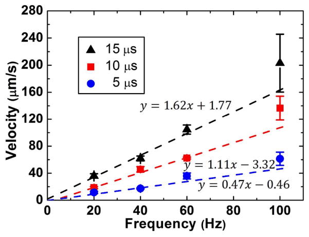
To transport objects at higher velocities using the OTMm, a longer laser pulse width or a higher pulse frequency can be used. This was experimentally verified by measuring the transport velocity of 20-μm-diameter polystyrene beads over a distance of 200 μm for different laser pulse widths (5 μs, 10 μs, 15 μs) and pulse frequencies (20 Hz, 40 Hz, 60 Hz, 100 Hz) (Fig. 4). Motorized linear actuators (Newport HF850) were used to translate the laser at a constant velocity for this measurement.
Fig. 4.
Measured transport velocities of 20-μm beads for varying laser pulse frequencies and pulse widths. Each point represents an average of three measurements, and the error bars represent the standard deviations. The function y = ax + b is used to fit the data in each frequency group.
The manipulation velocity increases with increasing laser pulse width due to a longer DO in each period, moving the object further per laser pulse. A higher laser pulse frequency means that the sequence shown in Fig. 2a repeats at a faster rate, so theoretically the transport velocity of an object and the frequency (y and x respectively in Fig. 4) should increase at the same rate (y/x = constant). To verify this, the linear function y = ax + b was used to fit the data of each pulse group. The errors for each point are used as instrumental weights, so data points with larger errors are less important in the fitting process. Thus, the y-intercepts should be nearly zero for y/x = constant, as shown on all the three fit lines in Fig. 4.
The OTMm requires a temperature gradient, but this is a concern for a manipulation system for living cells. However, it is challenging to precisely measure the temperature distribution of the fast-moving fluid under laser illumination in the microscale. The temperature distribution in the OTMm was probed with two temperature-sensitive polymers, poly(N-isopropylacrylamide) (PNIPAAm) and poly(NIPAAm-co-AAm) (Sigma-Aldrich)28 and the result is shown in ESI (Fig. S4).
A more important and pragmatic evaluation of the impacts of temperature and thermocapillary flow on NIH/3T3 cells is to measure the cell viabilities after manipulation by the OTMm (Fig. S5 in the ESI). The cells were manipulated with a laser pulse-width of 15 μs at a pulse frequency of 100 Hz, representing the harshest conditions used in the OTMm. The cells were allowed to circulate in the thermocapillary flow at least 20 times (a total duration of 10 to 15 seconds), compared to circulation for a maximum of 10 times during the micro-manipulation procedures described elsewhere in this paper. The viability test was performed on 108 cells, and showed a viability rate of approximately 98%. Only two cells were labelled as non-viable, but this may be due to the selection of cells that were dead prior to the OTMm manipulation.
In the cell patterning experiments described in this paper, a distance of at least 10 μm was maintained between the cell edge and the laser spot. This means the cell is outside the high-temperature region near the laser spot, as verified by the temperature-sensitive polymer experiments (Fig. S4 in the ESI). The laser pulse frequency was fixed at 100 Hz and the pulse width was tuned to a value that can finish the assembly in a reasonable time (within 10 minutes). However, the viability tests in Fig. S5 and the results in Fig. 4 suggest that the cells could be manipulated at a much faster velocity.
Single-Cell Patterning
NIH/3T3 cells (ATCC) were used as model cells for proof-of-concept cell patterning experiments. Prior to the experiment, the cells were cultured in Dulbecco’s Modified Eagle Medium (DMEM) supplemented with 10% bovine serum (ATCC), 100 U/ml penicillin, and 100 μg/ml streptomycin (Sigma-Aldrich) at 37°C in 5% CO2. At the time of the experiment, cells were detached by trypsin-EDTA (ATCC) and adjusted to a concentration of 6 × 10⁵ cells/ml. This cell mixture was mixed with hydrogel pre-polymer to form the working media for these experiments.
PEGDA and agarose are two hydrogels used in cell patterning19, 20, 29. PEGDA is a photo-curable synthetic polymer, while agarose is naturally derived and is cured by lowering the temperature. Cell patterning using these two hydrogels has usually been done using DEP forces19, 20. Here, we demonstrate programmable direct-cell patterning in these hydrogels.
Cell patterning in PEGDA
A two-dimensionsal 4 x 4 cell matrix was constructed in PEGDA using the OTMm. First, a pre-polymer was made of 10% (w/v) PEGDA (MW: 6000, Sigma-Aldrich) and a photoinitiator of consisting of 0.2% 2-Hydroxy-4′-(2-hydroxyethoxy)-2-methylpropiophenone (Sigma-Aldrich). The pre-polymer was mixed in a 1:1 volume ratio with the harvested NIH/3T3 cells in media to yield a working medium containing 5% PEGDA, 0.1% photoinitiator, and 3 × 10⁵ cells/ml. A 50-μl aliquot of this working medium was dispensed onto the substrate. The thickness of the dispensed aliquot on the substrate varied depending on the area of the media droplet. However, the media always had a thickness of greater than 100 μm, which is sufficient to cover the cells under manipulation. A thicker media droplet does not have any effects on the OTMm manipulation.
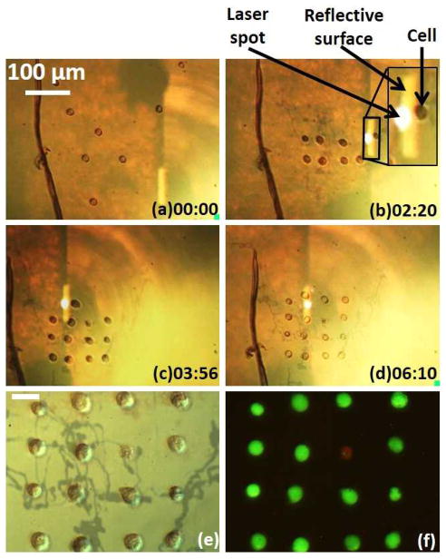
The entire assembly process for creating the 4 x 4 cell array took 6.5 minutes (Fig. 5a–d). The laser pulse frequency was 100 Hz. A laser pulse width of 7 μs was used to transport cells at an average velocity of 30 μm/s to positions 50 μm away from its final position. At this point, the pulse width was reduced to 5 μs, corresponding to an average transport velocity of 5 μm/s, to perform the final positioning of the cells. This reduction in pulse width ensures the accurate positioning of the cells under manipulation, while reducing the possibility of disturbing neighbouring cells.
Fig. 5.
Manipulation of NIH/3T3 cells in PEGDA. The time stamp format is minutes : seconds. (a–d) Cells are assembled by the OTMm. The inset shows a close image of the cell being manipulated. The reflective surface is the emitting surface of the laser diode, due to the match of the focal plane of the microscope objective lens and laser projection objective lens. (e) Single-cell pattern after PEGDA gelation. The dark tracks may be due to the laser heating of the substrate, but they do not affect the OTMm operation. The scale bar is 20 μm, and also applies to (f). (f) Viability test on the assembled cells. Green fluorescence indicates that the cell is viable, while red fluorescence indicates a non-viable cell.
After the cells were assembled, the media within the field-of-view of the microscope was exposed to a broadband UV source (90 mW/cm2 at 365 nm, X-Cite Series 120Q) for 15 seconds to photopolymerize the PEGDA. Uncured excess PEGDA pre-polymer was washed away by pipetting phosphate-buffered saline (PBS) solution directly onto the chip. The overall PEGDA gel area was about 30 mm2. The final cell pattern in the polymerized PEGDA is shown in Fig. 5e.
Cell viability was evaluated using the LIVE/DEAD cell viability/cytotoxicity kit (L-3224, Invitrogen). A 50-μl droplet of the working solution, containing 1 μM calcein AM and 2 μM EthD-1, was dispensed onto the PEGDA gel. The gel was kept at room temperature for 40 minutes before being examined under a fluorescent microscope. Fifteen of sixteen cells fluoresced green, indicating that they are viable. The remaining cell fluoresced red, indicating that it is not viable.
The transport velocities of the cells under manipulation were slower than those predicted from Fig. 4. This is due to the separation that was maintained between the cells and the generated bubble to avoid exposing the cells to a high temperature, as mentioned before.
Cell patterning in agarose
Agarose is a natural material, and is degradable by cellular enzymes, making it attractive as a cell scaffold19, 20, 29. However, the manipulation of cells directly in agarose is more challenging due to the higher viscosity of agarose solutions. Here, single cells were directly manipulated inside agarose in solution, and assembled into a pattern, followed by the gelation of the agarose. This experiment demonstrates the feasibility of using the OTMm to seed 3D cultures in agarose.
Agarose gelation is triggered by lowering the solution temperature. Thus, a cooling system was added to the OTMm to enable the gelation (Fig. S6 in the ESI). The OTMm substrate was stacked over a plain glass slide. The two pieces were separated by 100-μm-thick double-sided polyimide tape to form a cooling chamber. This chamber could be flushed with cold water to lower the temperature of the OTMm substrate, initiating agarose gelation.
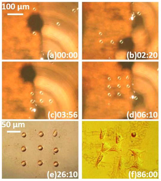
A solution of 4% (w/v) agarose (Type IX, ultra-low gelling temperature, Sigma-Aldrich) in PBS was made prior to the experiment. This agarose solution was mixed with media containing NIH/3T3 cells at a ratio of 1:3, yielding a solution of 1% agarose (viscosity: 7 cp)20 with a cell concentration of 4.5×10⁵ cells/ml. A 50-μl aliquot of the mixture was dispensed onto the OTMm substrate. It took less than 6.5 minutes to assemble nine cells into a 3 by 3 matrix (Fig. 6a–d). The laser pulse width was set 10 μs during cell transportation. Tuning the pulse width to a smaller value for the fine adjustment of the cell positions was no longer necessary in this experiment. This more viscous medium reduces the scale of the thermocapillary flow (Fig. S1c in ESI). The decreased flow velocity also reduced the average cell manipulation velocity to approximately 8 μm/s.
Fig. 6.
Patterning 3T3 cells in 1% agarose. The time stamp format is minutes : seconds. (a–d) Cells are assembled by the OTMm. (e) Single-cell pattern after agarose gelation. (f) Cells after one hour of culturing. The patterns visible underneath the cells are due to the laser heating of the agarose. This does not affect the manipulation. These patterns are also present in (e), but are more obvious in (f), due to imaging with differential-interference microscopy.
After the cell pattern is formed, an ice cube was put on one side of the cooling chamber, and filter paper was placed at the other side of the chamber to collect the icy melt-water. This lowered the substrate surface temperature down to 11 °C, in an ambient room temperature of 22 °C. The substrate was kept cool for 10 minutes, resulting in an agarose gel approximately 75 mm2 in diameter. The OTMm substrate was then separated from the cooling chamber and placed into a sterilized 35 mm × 10 mm tissue culture dish. A 2% agarose (low-melting point agarose, Promega) was poured into the dish to fix the whole chip firmly. The total thickness of the agarose was about 5 mm deep. Fig. 6e shows the single cell pattern inside the agarose hydrogel. Cell culture medium was dispensed on top of the agarose gel, and the dish was incubated at 37 °C in a 5% CO2 atmosphere. After one hour, eight of nine assembled cells spread and started migrating beneath the agarose (Fig. 6f, also in Fig. S7 in ESI)30, 31.
Conclusions
The OTMm is a programmable single cell manipulation platform requiring minimal micro-fabrication. It distinguishes itself by using optothermally induced fluid flow to manipulate cells instead of illuminating the cell directly. In comparison with optical tweezers, the OTMm uses half of the intensity to achieve more than twice of the force. Unlike optical tweezers, the OTMm is currently limited to manipulation of cells on a surface, although the manipulation of suspended cells may be possible by using intermediary structures between the laser-induced bubbles and the cells under manipulation, similar to the structures presented in ref. [32].
The OTMm is currently capable of manipulating micro-objects with diameters ranging from 6 μm for yeast cells25, to 136 μm for cell-laden agarose beads (preliminary experiments, data not shown). Future experiments are planned to investigate OTMm capabilities at the upper and lower ends of this size range.
Although not shown here, multiple light patterns could be projected onto the absorbing substrate to create parallel cell control32. The single laser used here can also have increased throughput, as the pulse width used (less than 20 μs) is far smaller than the pulse period (greater than 1ms), making it possible to run more than one hundred manipulation cases by directing the laser to different cells within a single period.
The substrate of the OTMm is another component that be improved in the future. Currently, ITO-coated glass slides are used since it is inexpensive, commercially available, and biocompatible. However, the ITO layer used here only absorbs 16% of the incident light energy. A more absorbent substrate material, such as gold-coated glass33 could be used. This can further reduce the incident light energy.
The manipulation results in PEGDA and agarose can also be optimized. For example, peptides or growth factors can be added into these pre-polymers to support cell viabilities and functions in long-term cultures34, 35. Other hydrogels such as gelatin methacrylate can also be used36. This hydrogel is photo-crosslinkable, has a low viscosity, and allows cell proliferation in 3D.
Supplementary Material
Acknowledgments
The authors would like to thank Prof. Daisuke Takagi for helpful discussion about the fluid mechanics around the cavitation bubble. This project was supported in part by Grant Number 1R01EB016458-01 from the National Institute of Biomedical Imaging and Bioengineering of the National Institutes of Health (NIH). These contents are solely the responsibility of the authors and do not necessarily represent the official views of the NIH.
Footnotes
Electronic Supplementary Information (ESI) available: [details of any supplementary information available should be included here]. See DOI: 10.1039/b000000x/
Notes and references
- 1.Théry M. Journal of Cell Science. 2010;123:4201–4213. doi: 10.1242/jcs.075150. [DOI] [PubMed] [Google Scholar]
- 2.Desai RA, Gao L, Raghavan S, Liu WF, Chen CS. Journal of Cell Science. 2009;122:905–911. doi: 10.1242/jcs.028183. [DOI] [PMC free article] [PubMed] [Google Scholar]
- 3.Gautrot JE, Trappmann B, Oceguera-Yanez F, Connelly J, He X, Watt FM, Huck WTS. Biomaterials. 2010;31:5030–41. doi: 10.1016/j.biomaterials.2010.02.066. [DOI] [PMC free article] [PubMed] [Google Scholar]
- 4.Liu JS, Gartner ZJ. Trends in Cell Biology. 2012;22:683–691. doi: 10.1016/j.tcb.2012.09.004. [DOI] [PMC free article] [PubMed] [Google Scholar]
- 5.Lindström S, Andersson-Svahn H. Lab on a chip. 2010;10:3363–72. doi: 10.1039/c0lc00150c. [DOI] [PubMed] [Google Scholar]
- 6.Lu Z, Moraes C, Ye G, Simmons CA, Sun Y. PloS ONE. 2010;5:e13542. doi: 10.1371/journal.pone.0013542. [DOI] [PMC free article] [PubMed] [Google Scholar]
- 7.Frutiger DR, Vollmers K, Kratochvil BE, Nelson BJ. The International Journal of Robotics Research. 2009;29:613–636. [Google Scholar]
- 8.Sakar MS, Steager EB, Cowley A, Kumar V, Pappas GJ. 2011 IEEE International Conference on Robotics and Automation. 2011:2668–2673. [Google Scholar]
- 9.Kawahara T, Sugita M, Hagiwara M, Arai F, Kawano H, Shihira-Ishikawa I, Miyawaki A. Lab on a Chip. 2013;13:1070–1078. doi: 10.1039/c2lc41190c. [DOI] [PubMed] [Google Scholar]
- 10.Ding X, Lin SCS, Kiraly B, Yue H, Li S, Chiang IK, Shi J, Benkovic SJ, Huang TJ. Proceedings of the National Academy of Sciences of the United States of America. 2012;109:11105–11109. doi: 10.1073/pnas.1209288109. [DOI] [PMC free article] [PubMed] [Google Scholar]
- 11.Grier DG. Nature. 2003;424:810–816. doi: 10.1038/nature01935. [DOI] [PubMed] [Google Scholar]
- 12.Mirsaidov U, Scrimgeour J, Timp W, Beck K, Mir M, Matsudaira P, Timp G. Lab on a Chip. 2008;8:2174–2181. doi: 10.1039/b807987k. [DOI] [PubMed] [Google Scholar]
- 13.Manaresi N, Romani A, Medoro G, Altomare L, Leonardi A, Tartagni M, Guerrieri R. IEEE Journal of Solid-State Circuits. 2003;38:2297–2305. [Google Scholar]
- 14.Wu MC. Nature Photonics. 2011;5:322–324. [Google Scholar]
- 15.Mohanty SK, Rapp A, Monajembashi S, Gupta PK, Greulich KO. Radiation Research. 2002;157:378–385. doi: 10.1667/0033-7587(2002)157[0378:camodd]2.0.co;2. [DOI] [PubMed] [Google Scholar]
- 16.Ichikawa A, Honda A, Ejima M, Tanikawa T, Arai F, Fukuda T. 2006 IEEE International Symposium on MicroNanoMechanical and Human Science; 2006. pp. 1–6. [Google Scholar]
- 17.Arai F, Onda K, Iitsuka R, Maruyama H. 2009 IEEE International Conference on Robotics and Automation; 2009. pp. 1832–1837. [Google Scholar]
- 18.Maruyama H, Iitsuka R, Onda K, Arai F. 2010 IEEE International Conference on Robotics and Automation; 2010. pp. 482–487. [Google Scholar]
- 19.Albrecht DR, Underhill GH, Wassermann TB, Sah RL, Bhatia SN. Nature Methods. 2006;3:369–375. doi: 10.1038/nmeth873. [DOI] [PubMed] [Google Scholar]
- 20.Albrecht DR, Underhill GH, Mendelson A, Bhatia SN. Lab on a Chip. 2007;7:702–709. doi: 10.1039/b701306j. [DOI] [PubMed] [Google Scholar]
- 21.Jones TB. Electromechanics of Particles. Cambridge University Press; Cambridge: 1995. pp. 36–48. [Google Scholar]
- 22.Pethig R. Biomicrofluidics. 2010;4:1–36. doi: 10.1063/1.3456626. [DOI] [PMC free article] [PubMed] [Google Scholar]
- 23.Martinez-Duarte R. Electrophoresis. 2012;33:3110–3132. doi: 10.1002/elps.201200242. [DOI] [PubMed] [Google Scholar]
- 24.Honegger T, Peyrade D. Lab on a Chip. 2013. [DOI] [PubMed] [Google Scholar]
- 25.Hu W, Fan Q, Ishii KS, Ohta AT. 16th International Conference on Miniaturized Systems for Chemisty and Life Sciences (MicroTAS); 2012. pp. 1654–1656. [Google Scholar]
- 26.Larkin BK. AIChE Journal. 1970;16:101–107. [Google Scholar]
- 27.Hu W, Ishii KS, Ohta AT. 2012 IEEE International Conference on Robotics and Automation; 2012. pp. 733–738. [Google Scholar]
- 28.Fundueanu G, Constantin M, Ascenzi P. Acta Biomaterialia. 2009;5:363–373. doi: 10.1016/j.actbio.2008.07.011. [DOI] [PubMed] [Google Scholar]
- 29.Zorlutuna P, Annabi N, Camci-Unal G, Nikkhah M, Cha JM, Nichol JW, Manbachi A, Bae H, Chen S, Khademhosseini A. Advanced Materials. 2012;24:1782–1804. doi: 10.1002/adma.201104631. [DOI] [PMC free article] [PubMed] [Google Scholar]
- 30.Lauffenburger D, Rothman C, Zigmond SH. Journal of Immunology. 1983;131:940–947. [PubMed] [Google Scholar]
- 31.Mendelson A, Cheung YK, Paluch K, Chen M, Kong K, Tan J, Dong Z, Sia SK, Mao JJ. Lab on a Chip. 2013;13:1156–1164. doi: 10.1039/c2lc41219e. [DOI] [PMC free article] [PubMed] [Google Scholar]
- 32.Hu W, Ishii KS, Fan Q, Ohta AT. Lab on a Chip. 2012;12:3821–3826. doi: 10.1039/c2lc40483d. [DOI] [PubMed] [Google Scholar]
- 33.Xie Y, Zhao C, Zhao Y, Li S, Rufo J, Yang S, Guo F, Huang TJ. Lab on a Chip. 2013 doi: 10.1039/C3LC00043E. [DOI] [PMC free article] [PubMed] [Google Scholar]
- 34.Franco CL, Price J, West JL. Acta Biomaterialia. 2011;7:3267–3276. doi: 10.1016/j.actbio.2011.06.011. [DOI] [PubMed] [Google Scholar]
- 35.Quintavalla J, Kumar C, Daouti S, Slosberg E, Uziel-Fusi S. Journal of Cellular Physiology. 2005;204:560–566. doi: 10.1002/jcp.20345. [DOI] [PubMed] [Google Scholar]
- 36.Ramón-Azcón J, Ahadian S, Obregón R, Camci-Unal G, Ostrovidov S, Hosseini V, Kaji H, Ino K, Shiku H, Khademhosseini A, Matsue T. Lab on a Chip. 2012;12:2959–2969. doi: 10.1039/c2lc40213k. [DOI] [PubMed] [Google Scholar]
Associated Data
This section collects any data citations, data availability statements, or supplementary materials included in this article.


