

Abstract
To improve the ability of an external cavity laser (ECL) biosensor to more easily distinguish true signals caused by biomolecular binding from a variety of sources of background noise, two photonic crystal (PC) resonant reflectors were incorporated into a single flow cell, with one of the PCs performing the detection function and the other one serving as a reference sensor. The ECL-based sensor system simultaneously emits at two distinct wavelengths corresponding to two different longitudinal cavity modes selected by the sensing and reference PC reflectors. The surface of the sensing PC filter was functionalized by a biomolecule recognition layer and exhibited narrowband reflection with the peak reflection wavelength at 856 nm. The reference PC was untreated and had the peak reflection wavelength at 859 nm. The PCs were bond to the upper and lower surfaces of a thin chamber frame, forming a flow cell. Utilizing the reference external cavity mode, the dual-mode ECL sensor system eliminated common-mode noise sources, including thermal drift, refractive index variations of the analyte solution, and nonspecific biomolecule binding.
Label-free biosensors based upon measuring wavelength shifts of optical resonant devices have been used effectively for characterizing biomolecular interactions.1, 2, 3 Recent demonstrations of passive optical resonators with high quality factor include whispering gallery mode spheres, microring resonators, liquid-core optical fibers, and nanobeam photonic crystal sensors.4, 5, 6, 7 The narrow resonant bandwidth of these approaches enables small resonant wavelength shifts to be accurately resolved for detection of low concentration analytes, individual nanoparticles, and small molecules. The operation of high quality factor passive optical resonators can require highly precise optical alignment for coupling light into the system, and often also demands highly precise fabrication tolerances for smoothness or gaps between waveguides and rings. Passive resonant reflectors, while achieving greater quality factor, also generally deliver reduced sensitivity, as measured by the magnitude of the resonant wavelength shift obtained for adsorption of biomolecules. To overcome these limitations, the external cavity laser (ECL) biosensor has been recently demonstrated.8 The ECL biosensor utilizes a semiconductor optical amplifier (SOA) as the gain medium and a photonic crystal (PC) reflectance filter as the wavelength-selective element to form an active optical cavity. The lasing wavelength value (LWV) is selected by the narrowband reflection from the PC and tuned by the attachment of biomolecules.8 While maintaining the bulk refractive index sensitivity of the PC passive resonator, the narrowing of PC resonant mode through the process of stimulated emission in the ECL cavity leads to high Q-factor (Q = 2.8 × 10⁷), which is comparable or higher than high Q optical resonators and existing laser-based label-free biosensors.9, 10, 11
A fundamental aspect of the ECL laser biosensor, as well as many types of optical biosensors, is the detection of wavelength shifts, which are indistinguishable from the change in resonant wavelength generated by an actual binding event.12 A change in the bulk refractive index of the test sample, the temperature of the test sample, thermal expansion of the sensor, thermally induced changes in the refractive indices of the sensor materials, or drift of the gain spectrum of the SOA can all modify the resonant wavelength of the sensor without the presence of biomolecular binding, and thus serve as sources of noise.12, 13 Further, as biosensors are generally prepared with a molecular recognition layer (such as an immobilized protein or nucleic acid layer), any attachment of biomolecules from the test sample to the sensor that is not due to binding of an immobilized molecule to its intended target also generates a wavelength shift that must be considered as a source of noise. In order to extract the signal of interest and to improve the accuracy of ECL biosensors, we developed a self-referencing approach based upon a dual-mode ECL. Dual-mode ECLs have been studied for applications in optical communications, atomic laser spectroscopy, and environmental monitoring, but this work represents its initial application to optical biodetection.14, 15, 16, 17, 18
In the dual-mode ECL sensor system, the two PCs are bonded to the opposite sides of a thin chamber frame, forming a flow cell that enables a test sample to be exposed to two PC sensors simultaneously. One of the PCs is modified with specific surface chemistry to perform the sensing function (termed the “active” or “sensing” PC), while the “reference” PC is untreated (or alternatively, treated with a biomolecular blocking layer that resists surface adsorption). Both PCs serve as wavelength selective mirrors for the external cavity laser cavity, which operates at two distinct lasing wavelengths corresponding to their own peak reflection wavelengths. The only constraint for the selection of the active and reference PC wavelengths is that both must fall within the gain spectrum of the SOA used for pumping the system. Because the test sample is introduced to both sensor surfaces simultaneously, any refractive index change of the test sample will induce equivalent shifts on both lasing modes. Likewise, because both the active and reference sensor share the same thermal environment, small temperature fluctuations of the test sample or in the room will be experienced by both sensors equivalently, thus automatically referencing the effects of thermal expansion, or thermally induced changes in the refractive indices of the sensor material components. Both sensors share all the optical components of the ECL system (SOA, optical fiber, mirror, and spectrometer), so any unintentional change to the instrument will be a common-mode effect. Finally, the active and reference sensors are exposed to the test sample and are thus subjected to the same nonspecific biomolecule binding. By simply subtracting lasing wavelength shifts of the reference sensor from the lasing wavelength shift of the active sensor, the system can accurately separate the biochemical binding signal from common mode noise signals.
The optical feedback in the dual-mode ECL cavity is provided by the narrowband PC resonant reflectors, as shown in Figure 1a. The PC slabs were fabricated using the nanoreplica molding process described in our previous publications.19, 20 In brief, a subwavelength grating structure was replicated from a silicon master wafer to a low refractive index ultra-violet curable polymer with a period of Λ = 550 nm and depth of t = 170 nm. To form a resonant reflectance near λ = 856 nm, a 100 nm thin film of TiO2 (refractive index = 2.4) was subsequently coated on top of the replicated grating on one PC surface. The reference PC sensor was coated with a slightly thicker 104 nm TiO2 layer to shift the resonant wavelength to 859 nm when immersed in deionized (DI) water. The resonant peak wavelength values (PWV) of the PC are modified by small changes of surface dielectric permittivity that result from attachment of biomolecules within the evanescent field region on the surface. We incorporate these two PC surfaces face-to-face as top and bottom surfaces of a flow chamber with a channel height of 3 mm, as shown in Figure 1b. The flow chamber was fabricated by cutting poly(methyl methacrylate) (PMMA) into the desired dimensions. Two cylindrical openings at the ends of the flow cell were tapped for screw-in attachment of 1/16 in. hose barb connectors, which served as an inlet/outlet ports for flexible polymer tubing.
Figure 1.
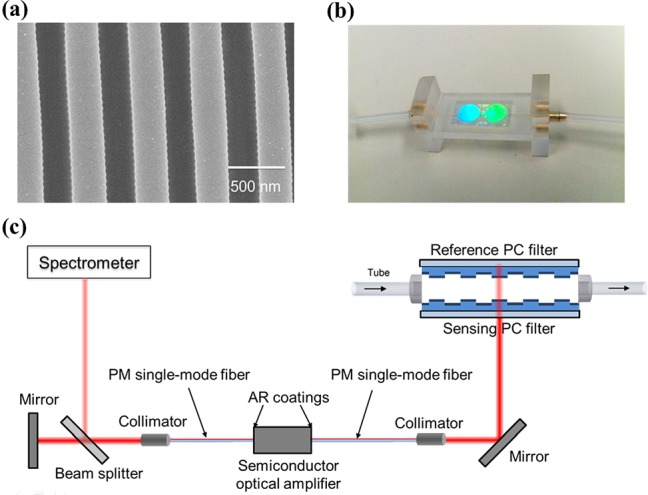
(a) SEM image of the PC structure. (b) Photograph of the flow cell where sensing and referencing photonic crystal sensors are incorporated as the upper and lower surfaces. (c) Schematic drawing of the dual-mode external cavity laser biosensor system.
The active medium of the dual-mode ECL biosensor system is a commercially available optical fiber-coupled semiconductor optical amplifier SOA (SAL-372-850, Superlum Inc.) with a center wavelength of λ = 850 nm and a 3-dB bandwidth of Δλ = 40 nm and with antireflection coating on both surfaces. The output from one end of the SOA is reflected back by a near-infrared reflection mirror, while the output light from another end of the polarization-maintaining (PM) fiber was directed towards the flow cell at normal incidence. The linear PC gratings are oriented for transverse magnetic (TM) mode incidence, with the electric field vector of the incident laser oriented perpendicular to the grating lines. The sensing and reference PCs reflect their own narrow resonant band of wavelengths, respectively, focused back into the SOA by the same path. An active optical resonator with two resonant modes was established with high quality factor through the stimulated emission process. A schematic drawing of the dual-mode external cavity laser setup is shown in Figure 1c. A small portion of the emitting laser light is delivered to a spectrometer with 0.02 nm resolution (HR4000, Ocean Optics). The lasing spectrum, gathered kinetically by the spectrometer at a sampling rate of 2 Hz, was fitted with Lorentzian functions to accurately determine the peak lasing wavelength, termed the LWV.
Since the two lasing modes share all optical components of the cavity in our configuration, thermal drift of the gain profile of the SOA will induce wavelength shifts on both the lasing modes thus can be effectively compensated in the dual-mode ECL biosensor system. In addition, the stream of test sample through the flow cell is introduced to both sensor surfaces simultaneously. The detection target will be selectively captured by the immobilized capture agent on the active sensor surface, generating a specific-binding signal. Inevitable thermal drift noise, non-specific binding of the analyte to the sensor surface, along with the slight variations of the bulk refractive index due to the mixing of the analyte solution, will generate equivalent noise signals to the sensing and reference devices. By performing lasing wavelength shift subtraction, the system can accurately eliminated common-mode error sources and extract the signal attributable to actual biochemical-binding on the active sensor.
First, we demonstrate dual-mode lasing in this system. The reflection spectrum of the PC filters and the emission spectrum of the dual-mode ECL are shown together in Fig. 2. Both measurements were taken with sensing and reference PC surfaces immersed in DI water, and the mode separation is 3.07 nm. In order to characterize the stability of dual-mode lasing operation and the feasibility of the self-referencing technique, three experiments were performed to assess the effects of environmental fluctuation, bulk refractive index variability, and the ability to measure specific adsorption of a protein to the sensing PC. In the first test to demonstrate the compensation of environmental fluctuations, laser emission wavelengths for both modes were simultaneously monitored over time, with the measurement results represented in Figs. 3a, 3b. Both of the signals gradually drifted downward, showing the impact of the room environment upon the sensors, for which no thermal control was applied. For a 3-min measurement, the standard deviations for these two signals are 1.4 pm and 1.3 pm, respectively. By subtracting these two signals, a self-referenced signal was obtained exhibiting reduced drift, as shown in Fig. 3c. Furthermore, the standard deviation of the baseline signal fluctuations was reduced to 0.8 pm.
Figure 2.
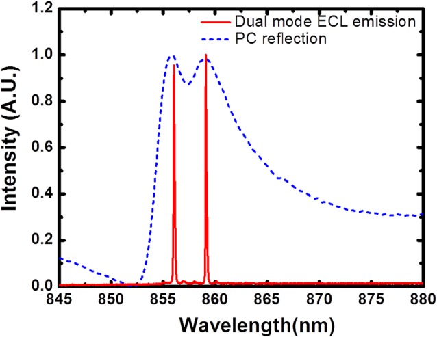
PC resonant reflection spectrum and dual-mode ECL laser emission spectrum when both PC sensor surfaces were immersed in DI water, showing a wavelength separation of 3.07 nm.
Figure 3.
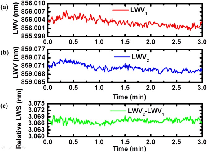
Dual-mode emission wavelengths as a function of time demonstrating the stability of the dual-mode ECL system and the ability to correct for the effects of small environmental fluctuations. Temporal variation of lasing wavelength values from (a) top PC and (b) bottom PC mode with DI water. (c) Relative laser wavelength shift shows a short-term standard deviation of 0.8 pm for this 3-min measurement.
In order to demonstrate the effect of a large common-mode shift, we induced bulk refractive index LWV shifts by the introduction of the solvent dimethyl sulfoxide (DMSO) to DI water with 1% concentration through the inlet into the flow cell. DMSO was selected because it is a commonly used solved in pharmaceutical high throughput screening assays that helps eliminate aggregation of potential drug compounds. Variation of DMSO concentration in optical biosensor assays used for measuring the binding of small molecules to immobilized proteins can easily result in a biosensor signal due to bulk refractive index effects that is greater than the wavelength shift due to small molecule detection, and thus represents an important noise source.12, 21 Utilizing rigorous coupled wave analysis (RSoft), we simulated the spectral response for the active and reference photonic crystal sensors. An identical linear dependence of the resonant wavelength shift on the bulk refractive index change is obtained, revealing a linear bulk refractive index shift coefficient of Sb = Δλ/Δn = 170 nm/RIU, not affected by the slightly different thickness of the TiO2 layer. To measure the effect of DMSO concentration on the dual-mode ECL biosensor, LWV was initially measured with DI water in the flow cell, establishing two baseline signals for the sensing and reference sensors. At t = 3.4 min, pure DI water was replaced by a 1% DMSO solution, and time sequence lasing wavelength data were measured after signal stabilization. We observed a 49 pm upward shifts on both lasing modes, indicating the higher refractive index of the DMSO solution. However, the self-referenced signal, Figure 4c demonstrates that both sensors undergo identical wavelength shifts, and that simple signal subtraction of the reference sensor from the sensing sensor results in no measurable shift, as desired, and had a standard deviation of 2.1 pm. This experiment also demonstrates that the bulk refractive index sensitivity was not dependent on the initial lasing wavelength of the sensor. This self-referencing system corrected the common-mode shift caused by the change of bulk refractive index of test sample.
Figure 4.
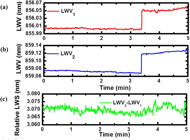
Response plots of laser emission wavelengths during a bulk fluid refractive index experiment demonstrating the ability of the reference sensor to undergo an identical wavelength shift as the active sensor, and thus to compensate for errors induced by bulk refractive index variation of the analyte. Temporal variation of lasing wavelength values of (a) top PC mode and (b) bottom PC mode with DI water as test sample (before 3.4 min) and with 1% DMSO solution (3.4 to 5 min). The introduction of DMSO solution induced 49 pm shifts simultaneously in both the lasing modes. (c) Subtraction of the bottom PC lasing wavelength shift from the top one results in effective elimination of bulk refractive index induced shift and shows a short-term standard deviation of 2.1 pm.
To demonstrate the self-referencing technique for detection of biomolecules, a simple assay for detection of pig immunoglobulin G (IgG) by immobilized Protein A was performed. In the sensor preparation phase, Protein A (Pierce Biotechnology) with a concentration of 0.5 mg/ml in phosphate-buffered saline (PBS) buffer (Sigma-Aldrich) was introduced to the surface of the active sensor, and allowed to incubate for 15 min. After rinsing the sensor surface three times with PBS to remove loosely bound Protein A, a PWV shift of 0.533 nm for the active PC was obtained, resulting in a PWV = 855.34 nm. The reference sensor PC with PWV = 859.45 nm was not functionalized with a biomolecular recognition layer, creating a reference to the Protein A/IgG binding signal. In the binding experiment, PBS solution was first injected into the flow cell to establish the baseline signals. Pig IgG (Sigma-Aldrich) diluted with 0.01 M PBS to a concentration of 0.5 mg/ml was introduced into the flow cell and allowed to incubate for 30 min, followed by a wash step to remove any unbounded IgG. This high concentration of IgG is meant to saturate all available Protein A binding sites on the active sensor, and to present a high concentration of protein to the untreated reference sensor. Kinetic LWV responses of two differential binding signals were obtained for the detection and reference sensors, as shown in Figs. 5a, 5b. The self-referenced signal was obtained by subtracting the non-binding signal from the binding signal, showing a ΔLWV = 2.15 nm. Because pig IgG will specifically bind to Protein A, this self-referenced binding signal indicates only the effect of the pig IgG binding, referencing out environmental fluctuations, bulk refractive index changes, as well as non-specific binding signals.
Figure 5.
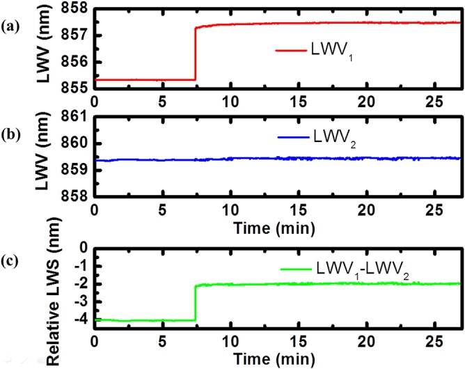
Kinetic response plots of laser emission wavelengths of the Protein A and pig IgG binding experiment. Temporal variation of lasing wavelength values of (a) sensing PC mode and (b) reference PC mode with PBS (before 7.5 min), followed by introduction of Pig IgG solution (7.5 to 22.5 min) and a wash step. (c) The self-referenced signal was generated by subtracting the binding signal from the non-binding reference signal, indicating only the effect of protein A and pig IgG binding.
In summary, a self-referencing ECL biosensor with dual-mode operation has been demonstrated and characterized. With two PCs assembled in a flow cell format serving as lasing wavelengths selection mirrors and with the semiconductor amplifier providing optical gain, this system achieves high Q-factor resonance and high-sensitivity label-free detection simultaneously. The ECL system simultaneously emits two distinct wavelengths selected by the sensing and reference PCs. Due to the close proximity and simultaneous exposure to test analytes of both sensors, the reference signal and binding signal share nearly all the common-mode error sources and their subtraction effectively eliminates these sources of noise. We have demonstrated stable dual-mode operation and have explored the feasibility of correcting common mode shifts caused by environmental fluctuations, variation in bulk refractive index of test sample by introducing DMSO solution. A simple biomolecular attachment assay was performed to further demonstrate the self-referencing technique. Future work on this self-referencing method will involve detection small molecules-protein interactions, where the detected signal is of similar magnitude to thermally induced noise, for applications in pharmaceutical development and life science research.
Acknowledgments
This work was supported by the National Science Foundation under Grant No. CBET 1132225, and National Institutes of Health under Grant No. R21 EB009695 A and Grant No. 2R01GM090220. Any opinions, findings, and conclusions or recommendations expressed in this material are those of the authors and do not necessarily reflect the views of the National Science Foundation and National Institutes of Health. The authors gratefully acknowledge Dr. J. Gary Eden of Laboratory of Optical Physics and Engineering at the University of Illinois at Urbana-Champaign for providing equipment and valuable discussions.
References
- Cunningham B. T. and Laing L., Expert Rev. Proteomics 3(3), 271–281 (2006). 10.1586/14789450.3.3.271 [DOI] [PubMed] [Google Scholar]
- Fan X., White I. M., Shopova S. I., Zhu H., Suter J. D., and Sun Y., Anal. Chim. Acta 620(1–2), 8–26 (2008). 10.1016/j.aca.2008.05.022 [DOI] [PMC free article] [PubMed] [Google Scholar]
- Homola J., Chem. Rev. 108(2), 462–493 (2008). 10.1021/cr068107d [DOI] [PubMed] [Google Scholar]
- Arnold S., Khoshsima M., Teraoka I., Holler S., and Vollmer F., Opt. Lett. 28(4), 272–274 (2003). 10.1364/OL.28.000272 [DOI] [PubMed] [Google Scholar]
- Chao C.-Y., Fung W., and Guo L. J., IEEE J. Sel. Top. Quant. Electron. 12(1), 134–142 (2006). 10.1109/JSTQE.2005.862945 [DOI] [Google Scholar]
- White I. M., Oveys H., and Fan X., Opt. Lett. 31(9), 1319–1321 (2006). 10.1364/OL.31.001319 [DOI] [PubMed] [Google Scholar]
- Quan Q., Burgess I. B., Tang S. K. Y., Floyd D. L., and Loncar M., Opt. Express 19(22), 22191–22197 (2011). 10.1364/OE.19.022191 [DOI] [PubMed] [Google Scholar]
- Ge C., Lu M., George S., Flood T. A., Wagner C., Zheng J., Pokhriyal A., Eden J. G., Hergenrother P. J., and Cunningham B. T., Lab Chip 13(7), 1247–1256 (2013). 10.1039/c3lc41330f [DOI] [PMC free article] [PubMed] [Google Scholar]
- Lu M., Choi S. S., Irfan U., and Cunningham B. T., Appl. Phys. Lett. 93(11), 111113 (2008). 10.1063/1.2987484 [DOI] [Google Scholar]
- Fang W., Buchholz D. B., Bailey R. C., Hupp J. T., Chang R. P. H., and Cao H., Appl. Phys. Lett. 85(17), 3666–3668 (2004). 10.1063/1.1807967 [DOI] [Google Scholar]
- He L., Ozdemir S. K., Zhu J., Kim W., and Yang L., Nat. Nanotechnol. 6(7), 428–432 (2011). 10.1038/nnano.2011.99 [DOI] [PubMed] [Google Scholar]
- Chan L. L., Cunningham B. T., Li P. Y., and Puff D., IEEE Sens. J. 6(6), 1551–1556 (2006). 10.1109/JSEN.2006.884547 [DOI] [Google Scholar]
- Yuen P. K., Fontaine N. H., Quesada M. A., Mazumder P., Bergman R., and Mozdy E. J., Lab Chip 5(9), 959–965 (2005). 10.1039/b501219h [DOI] [PubMed] [Google Scholar]
- Struckmeier J., Euteneuer A., Smarsly B., Breede M., Born M., Hofmann M., Hildebrand L., and Sacher J., Opt. Lett. 24(22), 1573–1574 (1999). 10.1364/OL.24.001573 [DOI] [PubMed] [Google Scholar]
- Laurent A., Chanclou P., Thual M., Lostec J., and Gadonna M., J. Opt. A: Pure Appl. Opt. 2(1), L6 (2000). 10.1088/1464-4258/2/1/102 [DOI] [Google Scholar]
- Moskalev I. S., Mirov S. B., Fedorov V. V., and Basiev T. T., Opt. Commun. 220(1–3), 161–169 (2003). 10.1016/S0030-4018(03)01346-4 [DOI] [Google Scholar]
- Zambon V., Piché M., and McCarthy N., Opt. Commun. 264 (1), 180–186 (2006). 10.1016/j.optcom.2006.02.021 [DOI] [Google Scholar]
- Lee K. S., Kim C. S., Kim R. K., Patterson G., Kolesik M., Moloney J. V., and Peyghambarian N., Appl. Phys. B 87(2), 293–296 (2007). 10.1007/s00340-007-2600-3 [DOI] [Google Scholar]
- Cunningham B., Lin B., Qiu J., Li P., Pepper J., and Hugh B., Sens. Actuators B 85(3), 219–226 (2002). 10.1016/S0925-4005(02)00111-9 [DOI] [Google Scholar]
- Cunningham B., Qiu J., Li P., and Lin B., Sens. Actuators B 87(2), 365–370 (2002). 10.1016/S0925-4005(02)00273-3 [DOI] [Google Scholar]
- Chan L. L., Cunningham B. T., Li P. Y., and Puff D., Sens. Actuators B 120(2), 392–398 (2007). 10.1016/j.snb.2006.02.047 [DOI] [Google Scholar]