Abstract
Measuring the three-dimensional motion of muscular tissues, e.g., the heart or the tongue, using magnetic resonance (MR) tagging is typically carried out by interpolating the two-dimensional motion information measured on orthogonal stacks of images. The incompressibility of muscle tissue is an important constraint on the reconstructed motion field and can significantly help to counter the sparsity and incompleteness of the available motion information. Previous methods utilizing this fact produced incompressible motions with limited accuracy. In this paper, we present an incompressible deformation estimation algorithm (IDEA) that reconstructs a dense representation of the three-dimensional displacement field from tagged MR images and the estimated motion field is incompressible to high precision. At each imaged time frame, the tagged images are first processed to determine components of the displacement vector at each pixel relative to the reference time. IDEA then applies a smoothing, divergence-free, vector spline to interpolate velocity fields at intermediate discrete times such that the collection of velocity fields integrate over time to match the observed displacement components. Through this process, IDEA yields a dense estimate of a three-dimensional displacement field that matches our observations and also corresponds to an incompressible motion. The method was validated with both numerical simulation and in vivo human experiments on the heart and the tongue.
Index Terms: Incompressible motion, tagged MRI, divergence-free vector spline, HARP
I. INTRODUCTION
Assessment of tissue motion is useful in the early diagnosis of certain diseases and for surgical planning [1]. This is especially true for the organs that are mostly formed of muscles—i.e., the heart and the tongue—whose functions are determined by the underlying muscle motion. Magnetic resonance (MR) tagging [2], [3] is the gold standard imaging technique for quantification of soft tissue motion. MR tagging places temporary markers (tags) in the tissue and these tags move and deform with the motion of the tissue. The acquired images can then be processed to find the in-plane motion—i.e., a two-dimensional (2D) projection of the three-dimensional (3D) motion—by identifying and tracking the intersections of the tag lines [4]–[6], by tracking whole tag lines [7]–[10], or by tracking every pixel using either the harmonic phase (HARP) [11], [12] or Gabor filter [13] approach. Methods have been developed to directly image the three-dimensional motion (cf. [14]–[17]), but they require too much time for routine clinical or scientific use. Instead, if reconstruction of a dense 3D motion field is sought, the only current practical option is to acquire a collection of images containing information about the one-dimensional (1D) or 2D motion components and to infer the full 3D motion field through interpolation.
The orientations of both the image slices and their tags should be coordinated properly so that the acquired images can be correctly used to interpolate 3D motion. For example, in cardiac applications, tagged MR images are usually acquired in short axis (SA) and long axis (LA) planes [18], as illustrated in Fig. 1(a). Typically, on each SA plane two images are acquired, one with horizontal tags encoding motion information in the x-direction, and the other with vertical tags encoding motion information in the y-direction. In this scenario, the LA images would be tagged in the horizontal direction in order to encode motion information in the z-direction. Tagged MR images of the tongue are usually acquired in two orthogonal orientations [19], for example the axial and sagittal orientations, as illustrated in Fig. 1(b). In one orientation, two sets of images are acquired on multiple parallel planes with horizontal and vertical tags, respectively. In the other orientation, images are acquired with tags in the through-plane direction of the first image orientation.
Fig. 1.
Illustration of tagged MR image acquisition for 3D motion.
In each of these two scenarios, motion measurements that can be computed directly from these images are sparse because the images themselves only sparsely sample the space due to imaging time constraints. As well, the measurements are incomplete because each tagged image contains only one or two in-plane components of the 3D motion, which means that each observation of displacement is not a complete three-dimensional vector. Therefore, in order to compute the motion and strain at an arbitrary tissue coordinate, these sparse and incomplete motion measurements must be combined in order to calculate the 3D motion of each point in the tissue.
Several approaches to the computation of 3D motion from collections of 2D observations from tagged MRI have been reported for both the heart [5], [6], [13], [18], [20]–[36] and the tongue [37], [38] (see also [19] for a review, and [39] for a comparison of four approaches [18], [20]–[22]). The approaches generally fall into four categories: finite difference methods, finite element methods, spline methods, and registration-based methods. Several approaches [35], [36] take into account the biomechanical behaviors of the heart to improve the motion reconstruction. It is not our intention to fully review these methods nor even to fully characterize their relative advantages and disadvantages. We do point out, however, that very few of these approaches have taken advantage of the fact that muscles are incompressible and therefore undergo volume-preserving deformations. It is widely accepted that the volume change of the myocardium during the cardiac cycle is less than 4% [40], [41]. Since this change is most likely associated with blood leaving the vessels during a contraction, it is likely that the tongue undergoes an even smaller volume change during its motion [42]. Since incompressible materials undergo deformations that preserve volumes at all scales and have divergence-free velocity fields, one should be able to improve interpolation results by exploiting this constraint.
An early approach by O’Dell et al. [18] did guarantee incompressibility, but this was done within a very restrictive finite element geometry that only loosely approximates the actual shape of the left ventricle. Denney et al. [20] directly applied the divergence-free constraint to reconstruct the 3D displacement field of the left ventricle (LV) of the heart in a finite-difference approach. However, that approach cannot guarante incompressible motion because the finite difference approximations were carried out on relatively coarse spatial and temporal grids. Neither of these two early approaches were optimized or validated with respect to their use of the incompressible approximation.
There has been a recent resurgence of interest in the estimation of incompressible motion. In 2007, Bistoquet et al. [30] used an incompressible deformable model to recover the motion of LV from anatomical cine MR images; this model was particular to LV anatomy and not easily adapted to the geometry of the available observations from tagged MRI. Later, the same group developed a nearly incompressible cardiac motion field from non-tagged MR images using a vector spline with divergence-free matrix-valued radial basis functions [31]. This method is more readily adapted to tagged MRI observations but is only approximately incompressible (see below). Very recently, diffeomorphic demons algorithm has been extended to include incompressibility and was tested on inferring motion from volumetric CT images [43]. Also in very recent work, Hinkle et al. [44] have developed an incompressible constraint for use in registration of respiratory CT images. These recent works are closer in spirit to our work than other works in the sense that they guarantee incompressible deformations from their underlying construction, but they have not been specifically developed for use in tagged MRI and therefore are not suitable for the sparse and incomplete data framework that we must assume herein. The incompressibility constraint was also adopted in a recent work by Moghaddam et al. [45] to compute the 3D strain on single slice from the measured 3D displacement data on that slice, but the method cannot be directly applied to 3D motion fields.
In this paper, we present an incompressible deformation estimation algorithm (IDEA) to reconstruct a 3D, dense, incompressible deformation field from tagged MR images based on divergence-free vector splines with sparse and incomplete data samples. In this method, incomplete observations of the 3D displacement vectors on the imaged tissue points are first computed from the tagged MR images using HARP processing [11], [12] and in-plane motion tracking. From the sparse and incomplete samples we seek a sequence of divergence-free velocity fields from which the final displacement field is computed by integration. The reconstructed displacement field also enables computing dense 3D Eulerian strain tensor everywhere inside the tissue.
This paper is organized as follows. Section II introduces the smoothing divergence-free vector spline. Section III explains our incompressible deformation estimation algorithm (IDEA) with incomplete data samples computed from tagged MR images. Section IV shows the experimental results of IDEA on numerical simulations, and in vivo images of both the heart and the tongue. Section V provides a discussion, and finally, Section VI concludes the paper.
II. DIVERGENCE-FREE VECTOR SPLINE
A displacement field u can be written as the integral of velocity over time t, i.e.,
| (1) |
The displacement field of a homogeneous, isotropic, and incompressible elastic body is volume preserving—i.e., the Jacobian determinant det [I + ∇u(x, t)] equals unity [46] with ∇ being the gradient operator and I being the identity matrix. Equivalently, the velocity fields that give rise to such a deformation must be divergence-free at all times—i.e., divv(x(t), t) = 0, where divv = ∇·v yields the divergence of v. In principle, there are two ways to go about reconstructing a displacement field from its samples: to enforce the Jacobian determinant condition or to enforce the divergence-free velocity field condition. It is quite challenging to enforce either condition, but the former is particularly problematic because it is a nonlinear constraint on the displacement field. Enforcing the divergence-free property of the velocity fields that can be integrated to yield a displacement field is a linear approach and therefore computationally more straightforward. This is the approach we utilize and is described in details in Section III. In this section, we provide necessary background on the application of vector splines in the estimation of divergence-free velocity fields.
In this work, divergence-free velocity fields are estimated using vector spline (VS) interpolation [47]. Vector splines couple the components of a vector field rather than treating them separately as is sometimes done using thin plate splines (TPS) [48] and B-splines [49]. In this way, the splines more accurately represent the underlying properties of a vector field.
Given N sample points in space xn = [xn, yn, zn]T, n = 1, … ,N, and vector-valued observations vn at these points, the VS interpolates a smooth vector field v(x) in order to minimize
| (2) |
where α and β are the weighting coefficients, and rotv = ∇ × v yields the curl of v. By weighting the two terms in Eqn. (2) differently, a vector spline can control the divergence and vorticity of the vector field separately. It has been shown that (2) has the closed form solution [47]
| (3) |
where cn are the unknown coefficients and K(x) is the matrix-valued kernel function given by
| (4) |
where I is the identity operator, Δ is the Laplacian operator, and h(x) = ‖x‖2k+1 is the solution to Δk+1h(x) = δ(x) with δ(x) being the Dirac delta function. Also, p(x) is the polynomial function of order k given (for k = 1) by
| (5) |
where d is a 12 by 1 vector containing the unknown coefficients.
The coefficients cn and d in the VS are found using the known vector values on the sample points by formulating
| (6) |
where 𝕂 is a 3N × 3N matrix with (𝕂)ij = K(xi − xj), ℙT = [AT (x1), … AT (xN)]T, , and C is a 3N × 1 vector with . After the unknown coefficients C and d are found by solving Eqn. (6), the vector value at any point x can be computed using Eqn. (3).
When α = β and k = 1, the function in Eqn. (2) becomes the bending energy that is minimized by the TPS. In particular, the three components of the interpolated vector field (Eqn. (3)) are decoupled because the kernel matrix 𝕂 is diagonal, and therefore the solution is equivalent to interpolating the three components independently using a standard TPS.
Another special case is when the VS constrains the resulting field to be divergence-free. Although a close approximation to this might be achieved by setting α ≫ β in Eqn. (2), the divergence-free vector spline (DFVS) directly imposes the constraint by solving
| (7) |
The DFVS solution is similar to that of the VS (Eqn. (3)) except that the kernel matrix becomes
| (8) |
and p(x) is also constrained to be divergence-free. The divergence-free constraint reduces the degrees of freedom of the linear part p(x) (see Eqn. (5)) from 12 to 11. After manipulation, one can get the linear part for DFVS can be expressed as
| (9) |
As the observed data are typically corrupted with noise, the spline should not be forced to precisely match the observed data—i.e., it should be a smoothing spline rather than an interpolating spline. Assuming the measured noise has Gaussian distribution, the smoothing VS solves
| (10) |
where ρ is a smoothing parameter, and J is the regularization term as defined in Eqn. (2). The smoothing VS solution has the same form as Eqn. (3), and its coefficients are solved using
| (11) |
III. INCOMPRESSIBLE DEFORMATION ESTIMATION ALGORITHM
Because direct reconstruction of an incompressible motion requires enforcement of a nonlinear constraint whereas enforcement of the divergence-free condition on velocity fields is mathematically straightforward (as shown above), we pursue here an indirect reconstruction approach in which a sequence of divergence-free velocity fields are integrated to produce the reconstructed displacement field.
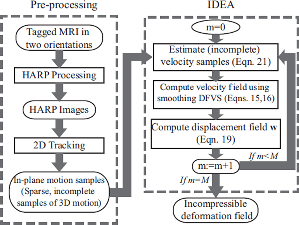
In the proposed method, we reconstruct incompressible motion from any given time frame back to the reference time frame t0, which is defined as the time when the tags are applied and have not deformed yet. Our approach to reconstruction of 3D incompressible motion is illustrated in Fig. 2. First, the tagged MR images are processed to give the sparse and incomplete measurements of the 3D motion. Second, these observations are used to estimate a sequence of 3D smoothing splines, each characterizing a divergence-free velocity field. Third, the final 3D displacement field is computed by integrating these velocity fields. It should be noted that the computed intermediate velocity fields are not intended to approximate the actual velocities of the object material points over time, but are merely computational entities that are used to guarantee that the computed displacement field corresponds to an incompressible motion.
Fig. 2.
The workflow for 3D incompressible motion reconstruction, which includes tagged MR image pre-processing and incompressible deformation estimation (IDEA).
A. In-Plane Motion from Tagged MR Images
In standard 1–1 SPAMM [2], [3] or CSPAMM tagging [51], tags are applied in 3D space and have a sinusoidal pattern at the reference time—i.e.,
| (12) |
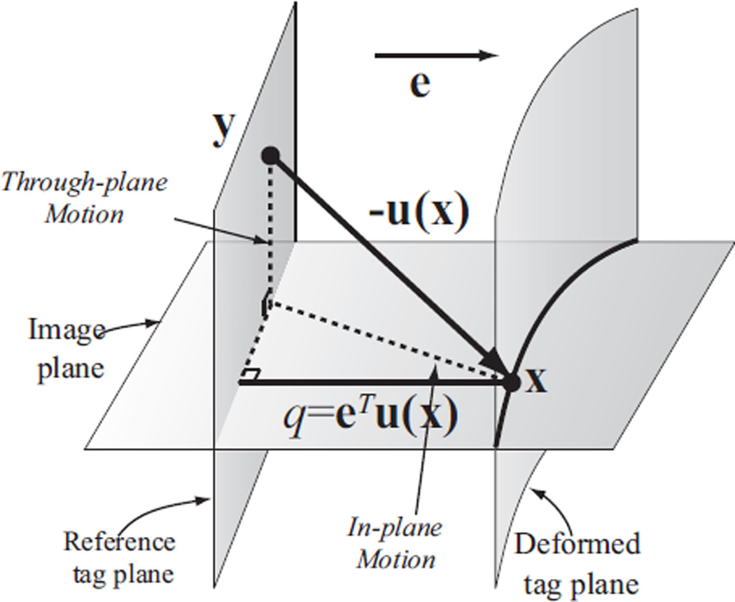
where α(x, t0) is called the tagging phase, f is the tagging frequency, φ0 is a constant phase offset, e is a normal vector, and x is a 3D point. The vector e is called the tagging direction, and is usually parallel to the image plane. Thus the points on a plane perpendicular to e have same tagging phases at the reference time (see Fig. 3), and deform in later time due to 3D tissue motion.
Fig. 3.
Displacement measurements from tagged images. Point y at the reference time moves to point x after deformation, which is observed on a tag line within the image plane. u(x) = x−y is the 3D displacement vector, and q is the projection of u(x) in the tagging direction e. From this image, only q can be measured and not u(x). (A detailed description is included in the body of the paper.)
A tagged MR image contains information about the object motion in the tagging direction, as illustrated in Fig. 3. In this diagram, the point that is found at position x on the image plane after deformation was originally located at position y at the reference time. From the tag properties measured on the image, it can only be determined that x originated from somewhere on a particular reference tag plane, but its location y on that plane is unknown. Thus, only the component q of u in the tagging direction e can be measured, as illustrated in Fig. 3. If two linearly independent tag directions are used—e.g., horizontal and vertical—then y is further restricted to belonging on a particular line at the reference time, but is otherwise unknown.
Measurements of motion are computed from the temporal sequences of tagged MR images using the harmonic phase (HARP) method [11], [12]. All images are first processed using HARP to yield sequences of harmonic phase images. The phase images at the reference time t0 are represented with synthetic phase images φ(x, t0) based on Eqn. (12), i.e.,
| (13) |
where W is a phase wrapping operator. The tagging frequency f and tagging direction e are known from the image acquisition protocol. By assuming the tags do not deform much by the first time frame, φ0 can be estimated from the HARP images at the first time frame [52]. Therefore, we can construct synthetic phase images at t0 using Eqn. (13). We synthetically generate the phase images at t0 instead of using the HARP images at the first time frame to reduce error, because though the acquired first frame is close to the reference frame, there is small deformation between t0 and the first time frame since the image acquisition requires time. Tissue points at each time frame are then tracked back to t0 using standard HARP tracking [11], which yields a measurement of the component q of the 3D displacement vector in the tagging direction (see Fig. 3), given by
| (14) |
for each point x in the image plane, and x = y − u(x, t). An advantage of HARP tracking is that it can track all tissue points on the images, and is not limited to points on the tag lines. All the tracked tissue points are used as sample points in the 3D motion reconstruction (explained later). We note that HARP tracking may fail when the motion between the two tracked time frames is large, which is also called tag jumping. To prevent HARP mistracking, we use the shortest path HARP refinement method [53].
On image planes that are tagged in only one direction, only one displacement projection per pixel is computed. On image planes that are tagged in two directions, two projections per pixel are computed. Knowledge of the 3D displacement can only be inferred once orthogonal image planes are considered together (see Fig. 1), and even then the only 3D displacements that can be directly observed from the raw measurements are those at the intersections of image planes. Furthermore, there is no displacement information at 3D points that do not lie on any image plane. Because of the irregular geometry of the combined positions of image planes—which are sometimes not even acquired with uniform spacing—the locations of the sample points, each having only partial information, are typically quite irregular.
In contrast to most other motion tracking and interpolation approaches in the literature, we do not use image frames that are observed at times between the reference time and the present time under consideration. This is because the observed tissues—those lying on image planes—are not the same tissues that are observed at later times (because of through-plane motion). Thus, the Lagrangian framework that is used to carry out incompressible deformation estimation (see next section) cannot take advantage of these observations.
B. Smoothing DFVS from Incomplete Samples
We have established that HARP processing gives measurements of displacement components in selected directions—the tagging directions—at the imaged tissue points. These incomplete data samples make it difficult to directly apply DFVS to interpolate divergence-free velocity fields as DFVS requires that the full 3D vector value is known at the sample points. Thus, DFVS must be modified to accommodate incomplete data samples. As well, a smoothing spline is needed instead of a interpolating spline due to image noise and inaccurate estimation of the data.
The incomplete samples of a velocity field can be written as: {xn, en, rn} for n = 1, 2, …, N, where en is a unit vector representing the tagging direction, and is the projection of the 3D velocity vector v(xn) in the direction en. Given N data samples, the minimization problem of a smoothing DFVS from incomplete data can be expressed as
| (15) |
where the first term is the smoothness term with JDF defined in Eqn. (7), the second term is the data term and comes from the incomplete data samples, and ρ is a smoothing parameter. Eqn. (15) is similar to Eqn. (10) except the data term, and thus they share similar solutions. Following the approach of Arigovindan [54], one can show that the solution to this problem is
| (16) |
where the coefficients cn are scalars, and KDF(x) and pDF(x) are as defined in Eqns. (8) and (9). The coefficients cn and d are found similarly as Eqn. (11) where in this case 𝕂 is a N × N matrix with , ℙT = [AT (x1)e1, …, AT (xN)eN], and V = [r1, .., rNT. This is different from the solution of Eqn. (10) because the data samples are just projections of the 3D vectors rather than the full 3D vectors themselves.
The smoothing parameter ρ affects the smoothness of the reconstructed velocity field. A larger ρ will produce a more smoother velocity field, but may also introduce a larger error.
C. 3D Incompressible Deformation Estimation Algorithm (IDEA)
At any time frame, an incompressible displacement field is estimated by integrating a sequence of divergence-free velocity fields. These velocity fields are not the true tissue velocities, but are instead computational entities created explicitly for the estimation of the displacement field. Let us define the integration variable as s, which takes on values in the interval [0, 1], and let the velocity of x at s be v(x(s), s). We define
| (17) |
with x(s) = x + w(x, s) and s ∈ [0, 1]. Then the displacement field u(x) = w(x, 1). The goal is to estimate the dense divergence-free velocity fields v(x(s), s) for s ∈ [0, 1] and the incompressible displacement field u(x) such that
| (18) |
with divxv(x, τ) = 0, ∀τ ∈ [0, 1], and for n = 1, 2, …, N.
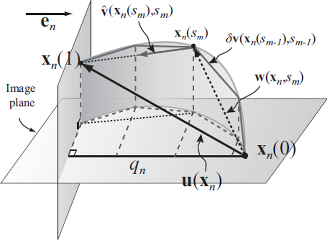
The problem can be reduced to a finite-dimensional problem by dividing the integration into discrete steps, i.e., sm = mδ for m = 0, 1, …, M with δ = 1/M, and estimating a velocity field at each step. It must be emphasized that the actual time interval between these discrete steps is generally not related to the time interval between the acquired MR data. The discretization process is illustrated in Fig. 4, which shows the final displacement of a sample point is computed by integrating its velocity over time discretely. If M is large enough, then the velocity can be assumed to be constant within each interval, so
| (19) |
for s ∈ [sm, sm+1). Thus (as shown in Fig. 4), and u(x) = w(x, 1). In general it is preferred to have a large M, as a large M can reduce the interpolation step size, and thus increase the accuracy and incompressibility of the reconstructed deformation field, but it will also increase the computation time.
Fig. 4.
Illustration of the discretized process of integrating velocity fields to compute the displacement field using one sample point. xn is a sample point, and u(xn) is its 3D displacement vector to be reconstructed. qn is the projection of u(xn) on en. u(xn) is reconstructed by integrating estimated velocity over discrete steps. (A detailed description is included in the body of the paper.)
We use smoothing DFVS from incomplete data samples to interpolate the divergence-free velocity fields separately over each integration interval. The velocity fields are computed sequentially starting from s0 = 0 through sM = 1. Let us denote for any step sm with v̂(xn(sm), sm) being the estimated velocity (explained below), and the data samples at sm are written as {xn(sm), en, rn(sm)} for n = 1, …, N.
At step sm, the velocity fields at steps between s0 and sm−1 have been computed. So we have and x(sm) = x + w(x, sm). This is illustrated in Fig. 4. The velocity at any sample point xn(sm) at sm is approximated by taking the first order expansion
| (20) |
so that
| (21) |
With the N data samples, the continuous velocity field v(x, sm) is interpolated with smoothing DFVS using Eqns. (15) and (16).
From Taylor’s expansion, the first order approximation of the velocity is accurate up to the order (1−δm)2. Therefore it is less accurate at smaller s and more smoothing is required at earlier steps. So the smoothing parameter ρ should be chosen to be large at small s and to decrease as s approaches 1. At sM−1, ρ should be set to 0 so that the final displacement w(xn, 1) matches the original data samples exactly—i.e., ln u(xn) = ln · w(xn, 1) = qn for n = 1, …, N. In practice, we choose the smoothing parameter at tm as , where ρ0 is determined empirically (described below).
Let yk for k = 1, …, K be a dense 3D grid of data points of which the 3D displacement vectors are to be computed. Our incompressible displacement estimation algorithm (IDEA) is summarized in Algorithm 1.
The iterative computation of both velocity and displacement fields in IDEA has several advantages. First, it assumes that each incremental displacement corresponds to a small deformation but the total displacement does not necessarily correspond to a small deformation. Under the small deformation assumption, the displacement field is approximately linear to the velocity and thus can be taken as divergence-free for incompressible motion. For large motions, the small deformation assumption is not valid and will result in large error if interpolation is carried out under the assumption of small deformation. Second, by integrating divergence-free velocity fields in discrete steps, IDEA avoids seeking a direct mathematical solution to the problem of incompressible motion reconstruction, which is nonlinear and computationally difficult to solve. Third, IDEA estimates the velocity samples through linear approximation, and reduces the approximation error using smoothing spline. This avoids directly constraining temporal smoothness on the trajectories at each point (see Section V for more details), and thus is much more computationally efficient.
Algorithm 1.
Incompressible Deformation Estimation Algorithm (IDEA)
| 1: | Initialize ρ0, M. Set yk(0) = yk, w(yk, 0) = 0, and w(xn, 0) = 0 for all k and n. |
| 2: | for m = 0 to M − 1 do |
| 3: | Set sm = mδ, ρm = ρ0(M − m− 1)/(M − 1); |
| 4: | Down sample the data points x(tm) if needed; |
| 5: | Compute rn(sm) using Eqn. (21) for all sample points; |
| 6: | Solve Eqn. (11) to compute the interpolating coefficients with samples {xn(sm), en, rn(sm)} and ρ = ρm; |
| 7: | Compute the velocities v(yk(sm), sm) and v(xn(sm), sm) using Eqn. (16); |
| 8: | Set w(xn, sm+1) = w(xn, sm) + δv(xn(sm), sm), w(yk, sm+1) = w(yk, sm) + δv(yk(sm), sm), xn(sm+1) = xn(sm)+w(xn, sm+1), and yk(sm+1) = yk(sm) + w(yk, sm+1); |
| 9: | end for |
| 10: | Set u(xn) = w(xn, sM) and u(yk) = w(yk, sM). |
D. Multi-Resolution
The computation of IDEA is dominated by solving the DFVS, which involves the inversion of a (N + 11) × (N + 11) matrix [see Eqns. (6) and (11)] with N being the number of data samples. Therefore its complexity is O(N3). To reduce computation time, a multi-resolution scheme is adopted.
At earlier integration steps, the sample points are subsampled with a sample rate η so that only a subset of the samples is used to interpolate the velocity field. In practice, η is chosen to be 4, 2, or 1, and decreases while the integration step m increases. The complete set of sample points, i.e., when η = 1, is used only during the last several integration steps. To subsample, on each image plane a subset of sample points is chosen as the tissue points located on a regular grid with a spacing of η pixels. Then the velocity components on all points in the subset are estimated (Eqn. (21)) and used in the DFVS interpolation. Afterward the 3D velocity values on all sample points, not just the subset used in the interpolation, are computed from the interpolation and to be used in later steps.
IV. EXPERIMENTS AND RESULTS
A. A 2D Example
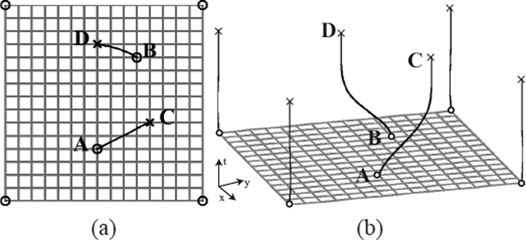
We first demonstrate IDEA using a simple example as shown in Fig. 5(a) that is similar to the one in [55]. In this example, we reconstruct a 2D dense deformation field using the displacements of six landmarks. Four of the landmarks are at the corner points of the grid and are fixed during the deformation; the other two landmarks A and B move to C and D, respectively. For comparison, the deformation fields are reconstructed using direct TPS interpolation, direct DFVS interpolation as explained in Section II, Bistoquet’s method [31], and IDEA. In Bistoquet’s method, the same divergence-free matrix-valued smooth kernel (MVSK) was used as in [31], i.e., K(x) = [ΔI − ∇∇T ]e−α‖x‖2. The trajectories of points A and B computed using IDEA with M = 50 steps are shown as the lines in Fig. 5(a) that connect A to C and B to D. Fig. 5(b) shows the temporal trajectories of the 6 landmarks.
Fig. 5.
A simple 2D example. (a) The 6 matched landmarks marked in circles: four fixed corner points, point A matching to point C, and point B matching to point D. (b) The temporal trajectories of the 6 landmarks computed using IDEA.
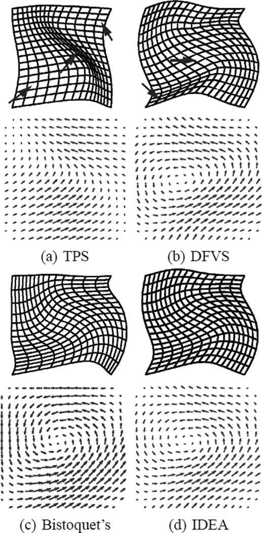
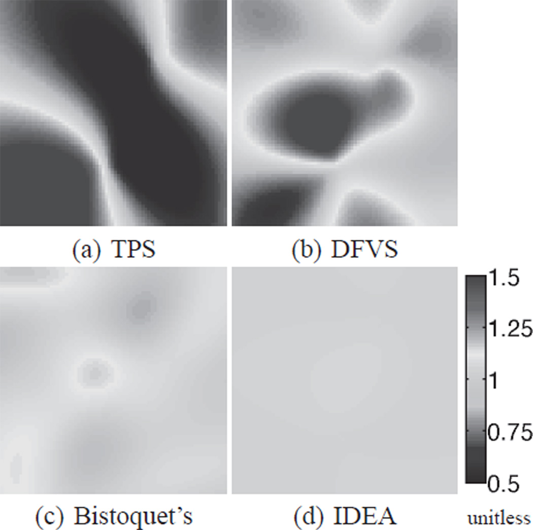
The deformation fields computed from all the four methods are shown in Fig. 6. It is observed that the areas of the mesh grids are not preserved in TPS and DFVS methods (red arrows), and they are better reserved in Bistoquet’s approach with MVSK and IDEA. The Jacobian determinants of the deformation computed using the four methods are shown in Fig. 7. The Jacobian determinant measures the compressibility of the deformation field, and a value of 1 means incompressible motion. TPS interpolation yielded a smooth deformation field but the incompressibility was not guaranteed. In DFVS, incompressibility was not achieved because for large deformations it is not correct to assume that the deformation field is divergence-free. Bistoquet’s approach nearly achieved incompressibility, but the reconstructed deformation field still had a considerable amount of compressibility, as shown in Fig. 7(c). Incompressibility was achieved by IDEA with only small error due to discretization.
Fig. 6.
The deformation fields computed using (a) thin-plate spline interpolation, (b) direct DFVS interpolation, (c) Bistoquet’s method with MVSK, and (d) IDEA. Top row: the deformed meshes. Bottom row: the vector fields. The arrows point to places that the incompressibility is clearly not preserved
Fig. 7.
The Jacobian determinant of the deformation computed using (a) TPS, (b) direct DFVS interpolation, (c) Bistoquet’s method with MVSK, and (d) IDEA. (1 means incompressible deformation.)
B. Cardiac Motion Simulation
To further validate IDEA, we performed a simulation experiment using a cardiac motion simulator for tagged MRI [56]. The simulator uses a confocal prolate spherical shell to simulate the shape of the left ventricle, and a 13-parameter model to describe the left-ventricular motion of the heart. The 13 time-varying parameters define rotation, translation, shears, ellipticallization, torsion, and radially dependent compression of the left ventricle. For given motion parameters, the simulator first generates the LV shape model and applies the motion. Then simulated tagged MR images at given image planes are generated. In our experiment, the LV was defined as a deformed prolate spheroidal shell, with a focal radius of 35 mm, an inner surface with radial prolate coordinate of 0.35 and an outer surface with radial prolate coordinate of 0.55. The motion parameter that controls compression was set to zero so that the simulated motion was incompressible. The values of the other parameters came from a bead experiment on a dog heart [57].
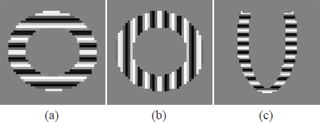
Tagged MR images were generated using the simulator on six SA planes with 10 mm separation and six radial LA planes with a 30 degree separation. On each SA plane two image sequences were generated with horizontal and vertical tags, respectively. One image sequence was generated on each LA image plane with tag planes parallel to the SA image planes. The tag spacing was 10 mm, and the pixel size of the images was 1.17 mm × 1.17 mm. The tags were applied at end-diastole and the image sequences were generated throughout the cardiac cycle. The period of cardiac cycle was 1 second, and 16 time frames were generated with a temporal separation of 66 ms. These images were all generated with no noise. Example images in the undeformed state are shown in Fig. 8.
Fig. 8.
Simulated tagged MR images. SA images with (a) horizontal tags and (b) vertical tags, and (c) LA image with horizontal tags at undeformed state.
In the simulation, the six SA image planes encompassed a slab with 50 mm thickness. For validation, the slab was sampled into 46 slices with 1. 11 mm separation, and the true LV motion on these slices was computed from the simulator and was taken as the ground truth. In the experiments, we first computed the sparse and incomplete motion samples from the image sequences on the six SA planes and six LA planes. Then the 3D motion on the 46 SA slices was reconstructed using IDEA and compared with the ground truth. IDEA was applied with parameters M = 20 and ρ0 = 1. 15. To compare, we also computed the displacement field using Bistoquet’s method [31]. In Bistoquet’s method, both the MVSK kernel and the DFVS kernel were tested and compared. These results were then compared to the ground truth.
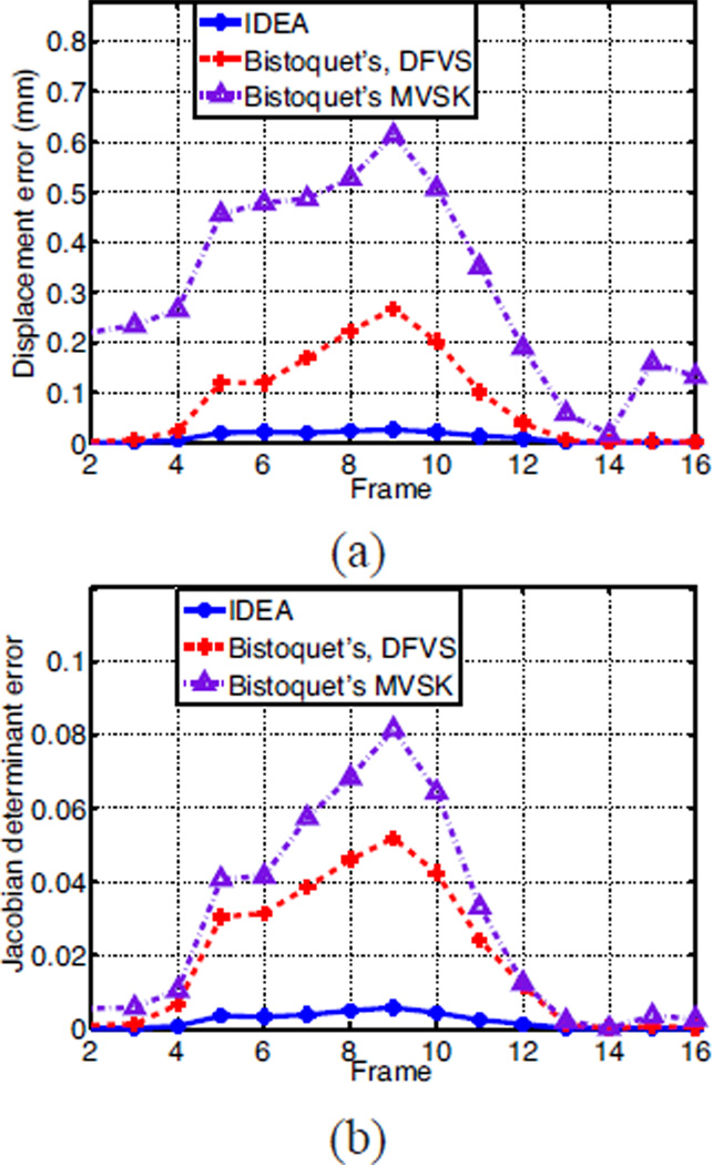
We computed the error between the reconstructed displacement field and the ground truth at all LV points on the 46 slices, and the mean magnitudes of the 3D displacement error are shown in Fig. 9(a). At the beginning and end of the cardiac cycle when the cardiac motion is small, both Bistoquet’s DFVS approach and IDEA produce negligible error. However, in the middle of the cardiac cycle when the cardiac motion is large, the error of Bistoquet’s DFVS approach is about 10 times greater than IDEA. In addition, Bistoquet’s method with MVSK produced much larger error at all time frames than with DFVS, indicating that in this application, DFVS performs better than MVSK. This is because MVSK is derived from a Gaussian kernel, which quickly decreases when the distance from the sample point increases. Thus MVSK may produce large error at points far from sample points especially when the samples are not uniformly distributed, as in the applications on tagged MR images.
Fig. 9.
The comparison of IDEA against Bistoquet’s method with both DFVS and MVSK. (a) The average displacement error and (b) the average error of the Jacobian determinant over all time frames.
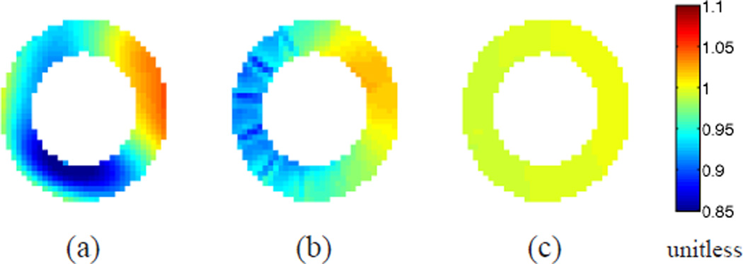
The average absolute difference between the Jacobian determinant and unity at all the time frames is shown in Fig. 9(b). Notice that incompressibility is much better preserved in IDEA than Bistoquet’s approach at all time frames. At the 9th time frame when all methods have the largest error, the average error of the Jacobian determinant in IDEA was 0.0056, Bistoquet’s method with DFVS was 0.052, and Bistoquet’s method with MVSK was 0.081. This is consistent with the fact that the divergence-free assumption of the displacement field is only valid for small deformations. Fig. 10 shows the Jacobian determinant computed from the three methods on one of the slices at that time frame.
Fig. 10.
The Jacobian determinant of deformation fields on one slice. (a) Bistoquet’s method with MVSK, (b) Bistoquet’s method with DFVS, and (c) IDEA.
C. Parameter Selection
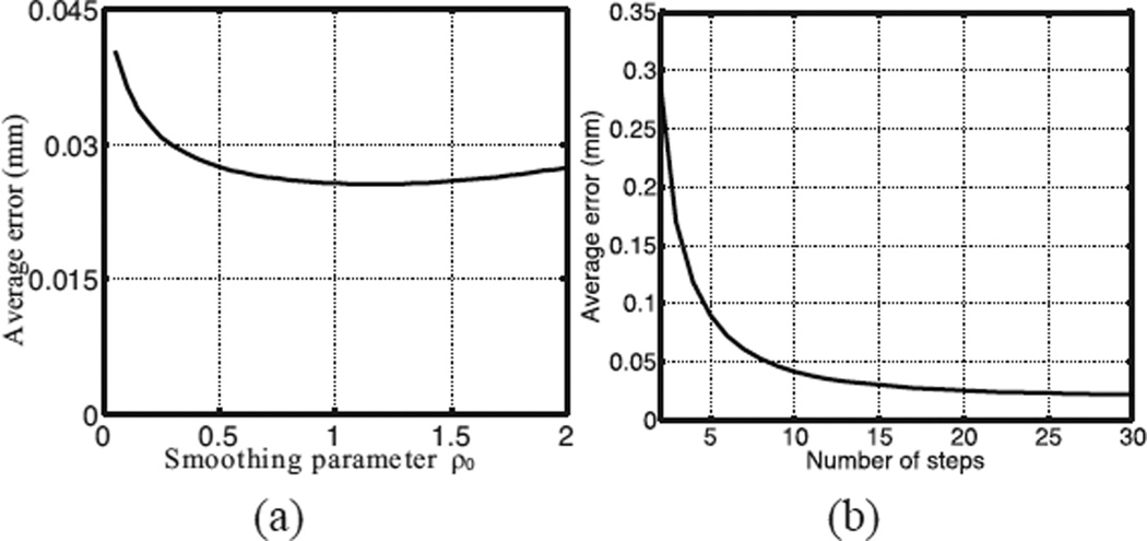
The accuracy of IDEA depends on the choice of the number of integration steps M and the initial smoothing parameter ρ0. To evaluate the parameter selection, we applied IDEA with varying M and ρ0 on the simulated cardiac images at the 9th time frame. The 9th time frame was picked because the deformation was the largest among all the time frames. First, the integration number M was fixed to 20, and the displacement fields were reconstructed with varying ρ0. The average displacement errors are computed and shown in Fig. 11(a). The error is small for all the selections of ρ0 (< 0.045 mm). It is minimal for ρ0 = 1.15 and slowly increases when ρ0 increases. This also shows that our method is robust to the selection of ρ0 because the error remains small for a reasonably large ρ0.
Fig. 11.
(a) The average displacement error of IDEA with varying smoothing parameter ρ0. (b) The average displacement error of our method with varying numbers of integration steps.
Next, we varied the number of steps while fixing ρ0 = 1.15, and the estimation errors are plotted in Fig. 11(b). The displacement error rapidly decreases when the the number of steps increases. This is expected because when the number of integration steps increases the step interval decreases and therefore the linear approximation of velocity at each step is more accurate. Because the computation time directly depends on the number of steps, in practice we chose M = 20 in our experiments.
The experiments show that the motion error decreases as M increases, and for fairly large M, the error does not change much. In addition, for a reasonable value of M, IDEA is fairly robust to the choice of ρ0 (see Fig. 11(a)). These observations can help choose the parameters for the in vivo experiments based on the tradeoff between accuracy and computation. It is not our intention to perform a full plane search for the optimal parameters in the simulation experiments because for different data the optimal parameters would not be exactly the same and it is not possible to perform the parameter search in all experiments.
D. In Vivo Cardiac Motion Experiments
Two sets of CSPAMM tagged MR images of the heart were acquired on two normal subjects on a Phillips 3T Achieva MRI scanner (Philips Medical Systems, Best, NL) equipped with a six channel phased array cardiac surface coil using a segmented spiral k-space data acquisition sequence with 10 spiral interleaves [58], 16 ms acquisition window, and ramped flip angle=20°. Both data acquisitions were performed during end-expiratory breath-hold with ECG gating. An approved IRB protocol was used and informed consents were obtained. The two data sets were imaged with similar parameters: spatial tag period = 12 mm, image size = 256×256, pixel spacing = 1.25 mm, slice thickness = 8 mm, temporal resolution = 30 ms, and TE = 0.85 ms. The number of time frames in each case was 20.
For both data sets, both horizontally and vertically tagged images were acquired on parallel SA image planes with a 4 mm slice separation. In the first data set, 12 SA slices were acquired, while 8 SA slices were acquired in the second data set. Eight LA images were acquired with horizontal tags in both data sets. However, only six of these in the first data set were used in our experiments because the other two were corrupted with imaging artifacts. All 8 LA slices in the second data set were used. All images were then processed using HARP to yield harmonic phase images from which the 2D motion on the SA slices and the 1D motion on the LA slices from the imaged time to the reference time were computed. In both data sets, the LV myocardium in all images was manually delineated and points inside these regions were used for motion reconstruction and validation.
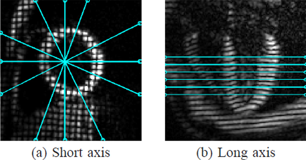
In the first data set, the 12 SA slices were divided into two interleaved groups (even and odd slice numbers) so that the slice separation within each group is 8 mm. The first group of six SA slices and all six LA slices were used to reconstruct 3D, dense, incompressible displacement fields of the LV. The six SA slices in the second group were used for validation. The relative slice locations of the six SA slices in the first group and the six LA slices are illustrated in Fig. 12. For motion reconstruction, IDEA was applied at all time frames with M = 20 integration steps and a smoothing parameter ρ0 = 1.15. We also computed the 3D displacement fields using Bistoquet’s approach [30] with DFVS for comparison. For validation, the reconstructed 3D displacements of points on the LV in the validation SA slices were projected to the 2D tagging directions, and compared with the 2D in-plane motion computed using HARP. The average displacement errors between the projected motion and the 2D motion computed using HARP were then computed and compared for both methods. The validation was not performed on the full 3D motion because it was not possible to get the true 3D cardiac motion from the data, while the 2D HARP tracking has been shown to have accuracy in the range of 0.1–0.2 pixels [11], [12]. The incompressibility of the reconstructed 3D motions was validated by computing Jacobian determinant of the motion fields at all time frames.
Fig. 12.
Tagged (a) SA and (b) LA images. The SA image shown is the product of the separately acquired horizontal and vertical tagged images only for visualization purpose. The lines overlaying these images depict the geometry of the acquired (a) LA and (b) SA images.
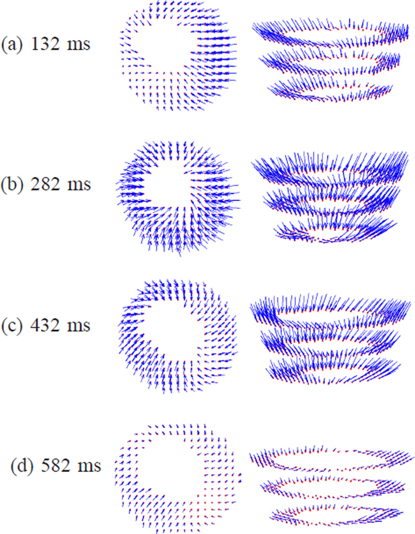
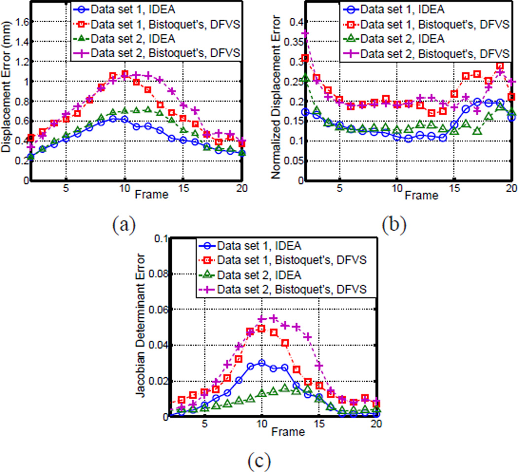
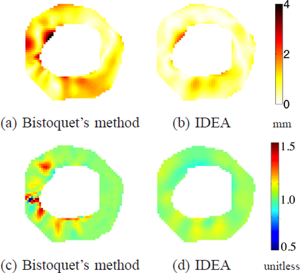
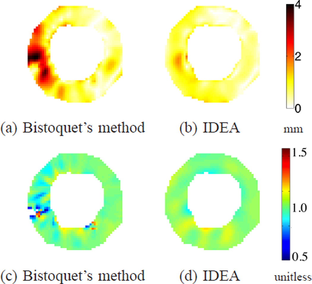
Fig. 13 shows the 3D motion of the first data set reconstructed using IDEA. The displacement fields in the LV regions on three SA slices are shown in two views at time frames 5, 10, 15, and 20, which are at 132 ms, 282 ms, 432 ms, and 582 ms after end-diastole. Since the displacement fields are Eulerian, the displacement vectors shown in Fig. 13 end on the spatial slices from which the data was collected, and start from where these material points were located at the reference time. The average displacement errors on all validation slices of both IDEA and Bistoquet’s method are shown in Fig. 14(a), and Fig. 14(b) shows the normalized displacement error which is computed as the average displacement error divided by the mean displacement magnitude at every time frame. In both methods, we observed larger error at the end of systole (the 10th time frame) because the displacement is larger. At the 10th time frame, the average displacement error of IDEA was 0.61 mm, and of Bistoquet’s method was 1. 08 mm. Figs. 15(a) and (b) show the displacement error maps on the 5th validation slice at the 10th time frame using IDEA and Bistoquet’s method, respectively. Figs. 16(a) and (b) show the displacement error maps on the 4th validation slice.
Fig. 13.
The 3D displacement fields of the first data set illustrated using three SA slices. From top to bottom: the displacement fields at different time frames; From left to right: two different views.
Fig. 14.
The comparison of the IDEA with Bistoquet’s method using DFVS on the two data sets. (a) The average displacement error, (b) the normalized average displacement error, and (c) the average error of Jacobian determinant over all time frames.
Fig. 15.
(a-b) The displacement error maps of the first data set at time frame 10 on the 5th slice for (a) Bistoquet’s method with DFVS and (b) IDEA. (c-d) The Jacobian determinant of the deformation field computed on the same slice for (c) Bistoquet’s method with DFVS and (d) IDEA. The mean magnitude of in-plane displacement of this slice is 6. 41 mm.
Fig. 16.
(a-b) The displacement error maps of the first data set at time frame 10 on the 4th slice for (a) Bistoquet’s method with DFVS and (b) IDEA. (c-d) The Jacobian determinant of the deformation field computed on the same slice for (c) Bistoquet’s method with DFVS and (d) IDEA. The shown slice is 8 mm closer to the apex point than the slice shown in Fig. 15. The mean magnitude of in-plane displacement of this slice is 4.77 mm.
Fig. 14(c) shows the average absolute difference between Jacobian determinant and unity on the validation slices at all time frames. At the 10th time frame when the heart deformed the most, the average absolute error of IDEA was 0.031. The deviation was mainly caused by both spatial and temporal discretization. The average deviation of Bistoquet’s method was 0.049. Figs. 15(c) and (d) show the Jacobian determinant resulting from the two methods at the 5th validation slice, and similarly, Figs. 16(a) and (b) show the Jacobian determinant on the 4th validation slice.
We also performed the similar validation experiments on the second data set. The average displacement error and Jacobian determinant error for IDEA and Bistoquet’s method were also shown in Fig. 14. Over all time frames, the maximal displacement error for IDEA was 0.71 mm at the 12th frame and the maximal displacement error for Bistoquet’s method was 1.06 mm at the 11th frame. The maximal average Jacobian errors for IDEA and Bistoquet’s method were 0.016 at 12th frame and 0.055 at 11th frame, respectively.
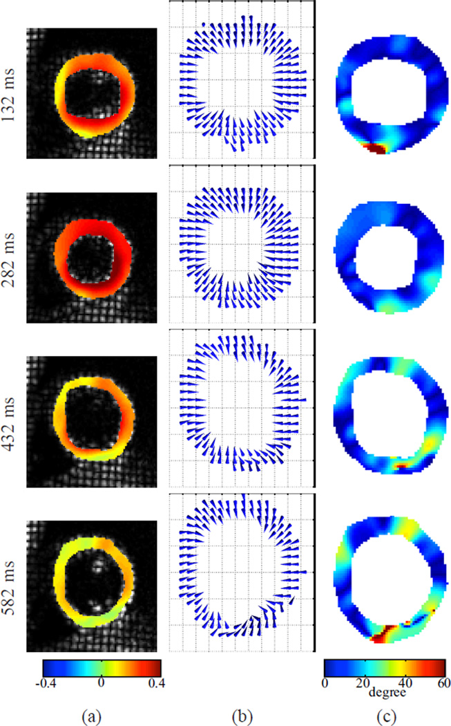
With the dense 3D displacement field constructed using IDEA, we computed the 3D Eulerian strain tensor [46] on all the SA slices, from which we also computed the principal strain. The first (largest) principal strain and strain direction measure the amount and the direction of the largest elongation or compression, and are important indicators of heart functions (cf. [59]). Fig. 17(a) and (b) show the first principal strain, and the strain directions on the first data set. It can be seen that the heart contracts during systole and relaxes afterward. The principal strain directions indicate that the contraction is predominantly along the radial direction. Fig. 17(c) shows the angles between the first principal directions and the radial directions of the heart. The radial direction is computed as the direction from each point to the center of mass of the myocardium. From the figure, one can see that the principal strain conformed with the radial direction, especially during systole (at times 132 ms and 282 ms). The average angle discrepancy, which was calculated as the average angular difference between the principal direction and the radial direction, at the four displayed time frames were 12.6, 10.4, 14.8, and 23.5 degrees respectively.
Fig. 17.
The first Eulerian principal strain in the LV region on one SA slice at four time frames for the first data set. (a): principal strain, which is unitless; (b): principal strain directions; (c): the angles between the principal directions and the radial directions.
E. Tongue Motion Experiment
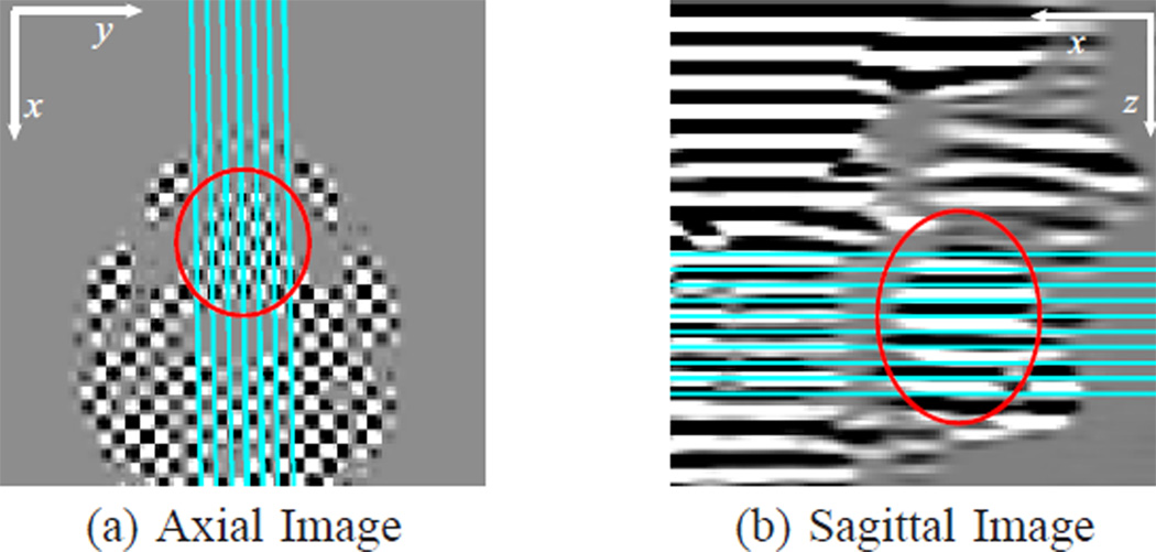
A tongue motion experiment was performed on a normal subject during speech. Tagged MR images were acquired on a Siemens 3T Tim-Trio MRI scanner (Siemens Medical Solutions, Malvern, PA) with head and neck coils using a segmented gradient echo sequence. Acoustic cues were used to synchronize speech utterance repetitions with image acquisition and trigger the scanner [60]. The imaging parameters were: flip angle = 10°, spatial tag period = 12 mm, FOV = 240 mm, slice thickness = 6 mm, temporal resolution = 47 ms, number of time frame = 20. The acquired k-space matrix size was 62×22, and the images were reconstructed to 128×128 with pixel spacing of 1.875 mm. The speech material studied was “eeoo”. Images were acquired on 10 axial slices and 7 sagittal slices to cover the whole tongue. On each axial slice, two images were acquired with orthogonal tag directions. On each sagittal slice, one image was acquired with tag planes parallel to the axial slices. Fig. 18 shows the relative locations of the imaged slices.
Fig. 18.
Tagged (a) axial and (b) sagittal images. The axial image shown is the product of the separately acquired horizontal and vertical tagged images. The lines overlaying these images are the intersections of the shown images with the acquired (a) sagittal and (b) axial images. The red circles show the tongue location in the images.
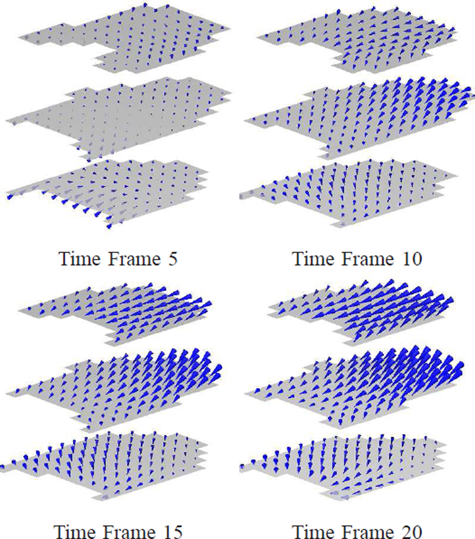
The reconstructed 3D incompressible tongue motions at selected time frames are shown in Fig. 19. The three shown slices are the 1st, 4th, and 7th axial slices whose spatial locations are shown in Fig. 18(b) as the 1st, 4th, and 7th lines from the top.
By visually checking the images, we have found that the transition from “ee” to “oo” happens from the 8th to 12th time frames. Notice that from the reconstructed motion, during “ee” (time frames 1–7), the top part of the tongue (see the top slice in the figures) does not move much, while the bottom part (see the bottom slice in the figures) is moving forward and a little upward. This is because the top of the tongue is touching the palate, which prevents the tongue from moving up. In the meantime, the muscle at the bottom part of the tongue is moving up and forward to push the tongue again the palate. During the transition from “ee” to “oo” (time frames 8–12), the whole tongue starts to move downward and backward, and the top part of the tongue moves more than the bottom part. After the transition (time frames 13–20), the tongue holds its position to pronounce “oo” continuously.
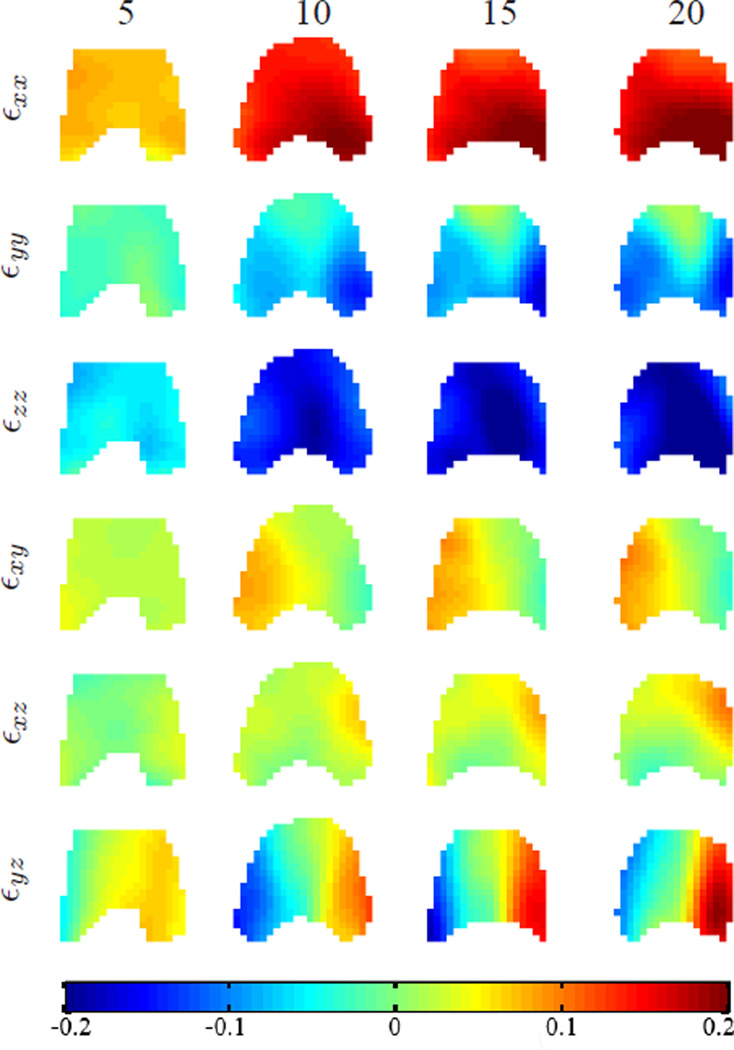
The 3D Eulerian strain tensor was computed using the reconstructed 3D dense motion. Fig. 20 shows the components of Eulerian strain tensors on the first axial slice at four time frames. Though the exact relationship between 3D strain and tongue muscle activation remains a challenging problem and requires more exploration, the 3D strain tensor computed from IDEA results has the potential to provide more insights into and benefit future scientific research on this problem.
Fig. 20.
The components of 3D Eulerian strain tensor on the 1st axial slice at different time frames. From left to right are the strain maps at time frames 5, 10, 15, and 20. The slice location is shown as the 1st line from top in Fig. 18(b). The x, y and z axis are as defined in Fig. 18 and the tongue tip is upward. The strain is unitless.
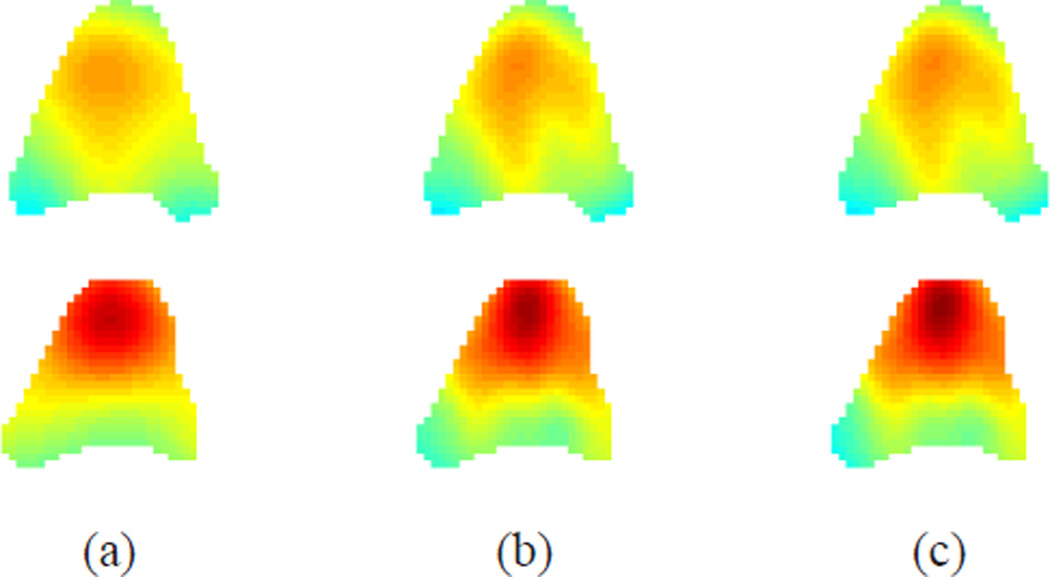
For comparison, we also reconstructed the 3D motion using Bistoquet’s methods with MVSK and DFVS. The kernel size in MVSK was selected as 10 mm. Fig. 21 shows the through-plane motion components on one selected axial slice from the three methods as a visual comparison. It can be seen that, for the tongue the IDEA results were similar to Bistoquet’s method with DFVS, and were slightly different from Bistoquet’s method with MVSK. This is partially due to the fact that the tongue motion is not as complicated as the cardiac motion, and a large amount of the motion was captured in the linear part of DFVS. We did not perform quantitative evaluations on the three methods because no ground truth was available, and also because IDEA was numerically validated in cardiac experiments.
Fig. 21.
The reconstructed z-motion (through-plane motion) on a selected axial slice at the (top row) 10th and (bottom row) 20th time frames using (a) Bistoquet’s method with MVSK, (b) Bistoquet’s method with DFVS, and (c) IDEA.
F. Computation
IDEA was implemented in C and compiled so that it could be called from Matlab (Mathworks, Natick MA); it was then run on a server with 4×3.57 GHz processors and 32 GB RAM. As described earlier, the complexity of the method is O(N3) with N being the number of samples. In the cardiac experiments, the number of samples were around 22,000 and varied at different time frames. The adopted multi-resolution scheme in IDEA greatly reduced the computation time while not affecting the accuracy of the displacement field reconstruction. In our implementation, IDEA took about 50 minutes to reconstruct the displacement field at one time frame, while Bistoquet’s method took about 25 minutes.
The computation time should not pose serious limitations for scientific studies with a fairly small number of data sets. For clinical use and the processing of large number of data sets, it is possible to reduce the computation time by optimizing our implementation, including the adoption of optimized matrix inversion algorithm, parallel computing, for example.
V. DISCUSSION
It is possible to use other divergence-free kernel matrices to interpolate or approximate divergence-free velocity fields, e.g., the smooth kernel that was developed by Narcowich and Ward [61] and adopted by Bistoquet et al. [31] in their nearly incompressible model, and the class of divergence-free kernels [62] that was derived from the compactly-supported Wendland functions 63] and applied to certain incompressible fluid flows. Compared to the DFVS kernel, these kernels have a higher order of smoothness, and have either compact support or are rapidly decreasing. However, they require careful parameter tuning. In addition, we have found that although the matrix 𝕂 in Eqns. (6) and (11) is theoretically positive definite, when the number of samples is large 𝕂 can be close to singular to the working precision of computer and cannot be inverted. This is especially a problem for our application since the number of data samples is usually large (~20,000 samples). This may be improved by choosing large supports for Wendland function-based kernels, or small variance for the smooth kernels, but it will decrease the interpolation accuracy.
In IDEA, the strategy of estimating velocity fields at discrete time steps and integrating them together to reconstruct the displacement field is similar to that in landmark matching via large deformation diffeomorphism (LMLDD) [55]. The main difference is that LMLDD seeks smooth trajectories over time by directly constraining the temporal smoothness of velocity fields. It is possible to extend LMLDD to incompressible motion reconstruction by enforcing the divergence-free velocity condition. Though incompressible LMLDD appears a good solution to our application, it is not feasible due to unaffordable computation because of the large number of data samples (>20,000) in our application.
In the image registration community, the incompressibility constraint has also been studied especially for contrast-enhanced image registration [64]–[66]. These methods model the incompressibility using the facts that the Jacobian determinant of deformation equals unity [64], [65], or the velocity fields are divergence free [66]. Recently, Mansi et al. [43] estimated 3D cardiac motion using diffeomorphic demons image registration with an incompressibility constraint. It is possible to apply the IDEA to these incompressible image registration problems, and is part of our future work.
In the in vivo cardiac motion experiment, the principal strain direction computed from the reconstructed incompressible motion (Fig. 17) showed that during systole the myocardial muscles contracted mostly in the radial directions, and the contraction increased with time and could be as large as 30–40%. During diastole the myocardial muscles relaxed and thus presented decreased principal strain. At end-diastole, the principal strains were close to zero, and thus the estimated principal strains were dominated by noise. In this case the noise would not greatly affect the magnitude of principal strains, but would cause large errors on the principal directions. As a result, the strain directions at end-diastole were less informative as they were dominated by noise. This effect can be seen from the lower part of the myocardium in Fig. 17 at time 582 ms. Similarly, the noise would also cause large error at regions that had small strains at other time. Nonetheless the strain analysis from the reconstructed 3D incompressible motion may promote the understanding of muscle motion and strain patterns, and the correlations between the motion and the organ functions for both the heart and the tongue. This is our future work.
In the cardiac experiments, the images at SA and LA planes were acquired at different breathholds. Thus there can be mismatching between the image slices when there is patient motion between short axis and long axis image acquisitions and/or short axis images with different tagging directions. The sagittal and axial images in the tongue experiments can also be mismatched for similar reason. Though no mismatching was observed in the data used in the paper, this could be a potential source for motion reconstruction error, and may need to be compensated.
In our experiments, the smoothing parameter ρ is set to 0 at the final step of the integration procedure so that the reconstructed motion matches the samples exactly. As shown in [11], [12], the HARP tracking is accurate up to 0.1–0.2 pixels. Thus the 2D and 1D motion samples computed from HARP and HARP refinement are considered reliable and accurate. In the case of noisy data samples, ρ at the final step can take a small value for better smoothing.
In this paper, IDEA was applied to reconstruct 3D motion from the sparse and incomplete motion components computed from tagged MR images. IDEA can also be readily applied to the sparse motion computed from other motion encoded images, including DENSE [67], zHARP [15], and slice-following tagging [68]. In particular, IDEA can be applied to the 3D motion imaging methods, for example, zHARP and 3D-DENSE [17] with minor changes. These 3D imaging methods are different from tagged MR imaging in that each imaged slice encodes the full 3D motion instead of 1D or 2D projections as in tagged MR images. In this case, the images need be acquired and displacements are computed only on a set of parallel slices. On each sample point, the displacement vector can be taken as three samples, each with the motion component on one dimension. These samples can then be used in the smoothing DFVS problem as in Eqn. (15) and solved using IDEA.
Finally, although the potential benefits of IDEA have been demonstrated on both simulation and actual data in this paper, the evaluations are relatively few in number. And although it has been compared here to a leading method in the literature, there are other existing methods to which it could be compared. Therefore, a more complete evaluation on more numerous data sets and a broader comparison against other algorithms should be carried out in the future.
VI. CONCLUSION
In this paper, we presented an approach, IDEA, to reconstruct a 3D, dense, incompressible displacement field from tagged MR images. IDEA uses a divergence-free vector spline on incomplete and non-uniform sample data to interpolate velocity fields at discrete integration steps, and the displacement field is computed by integrating these velocity fields. In comparison to previous methods, IDEA does not assume small deformations, and the reconstruction of displacement field at one time frame does not rely on the results from earlier time frames. Hence it prevents error accumulation arising from inaccurate estimation at earlier time frames caused by the small deformation assumption. IDEA was validated with both numerical simulation and in vivo experiments, and has been successfully applied to reconstruct both the motion of the left ventricle of human heart and the tongue motion during speech.
Fig. 19.
The 3D displacement fields of the tongue illustrated using three axial slices at frames 5, 10, 15, and 20. (The tongue tip is toward the right.)
ACKNOWLEDGEMENT
This work was supported by NIH/NHLBI grant R01HL47405, NIH/NCI grant R01CA133015, and NIH/NIDCD grant R00DC009279.
Contributor Information
Xiaofeng Liu, General Electric Global Research Center, Niskayuna, NY, 12309 (xiaofeng.liu@gmail.com).
Khaled Z. Abd-Elmoniem, National Institute of Diabetes and Digestive and Kidney Diseases, National Institutes of Health, Bethesda, MD, 20892
Maureen Stone, Departments of Neural and Pain Sciences, and Orthodontics, University of Maryland Dental School, Baltimore, MD, 21201.
Emi Z. Murano, Departments of Otolaryngology, Head and Neck Surgery, Johns Hopkins School of Medicine, Baltimore, MD, 21205
Jiachen Zhuo, Department of Diagnostic Radiology and Nuclear Medicine, University of Maryland School of Medicine, Baltimore, MD, 21201.
Rao P. Gullapalli, Department of Diagnostic Radiology and Nuclear Medicine, University of Maryland School of Medicine, Baltimore, MD, 21201
Jerry L. Prince, Department of Electrical and Computer Engineering, Johns Hopkins University, Baltimore, MD, 21218 (prince@jhu.edu).
REFERENCES
- 1.Kolipaka A, Chatzimavroudis GP, White RD, Lieber ML, Sester RM. Relationship between the extent of non-viable myocardium and regional left ventricular function in chronic ischemic heart disease. J. Cardiovasc. Magn. Reson. 2005;vol. 7(no. 3):573–579. doi: 10.1081/jcmr-200060652. [DOI] [PubMed] [Google Scholar]
- 2.Zerhouni EA, Parish DM, Rogers WJ, Yang A, Shapiro EP. Human heart: tagging with MR imaging – a method for noninvasive assessment of myocardial motion. Radiology. 1988;vol. 169:59–63. doi: 10.1148/radiology.169.1.3420283. [DOI] [PubMed] [Google Scholar]
- 3.Axel L, Dougherty L. MR imaging of motion with spatial modulation of magnetization. Radiology. 1989;vol. 171:841–845. doi: 10.1148/radiology.171.3.2717762. [DOI] [PubMed] [Google Scholar]
- 4.Amini AA, Chen Y, Curwen RW, Manu V, Sun J. Coupled B-snake grides and constrained thin-plate splines for analysis of 2-D tissue deformations from tagged MRI. IEEE Tran. Med. Imag. 1998;vol. 17:344–356. doi: 10.1109/42.712124. [DOI] [PubMed] [Google Scholar]
- 5.Kerwin WS, Prince JL. Cardiac material markers from tagged MR images. Med. Imag. Anal. 1998;vol. 2(no. 4):339–353. doi: 10.1016/s1361-8415(98)80015-7. [DOI] [PubMed] [Google Scholar]
- 6.Young AA, Kraitchman DL, Dougherty L, Axel L. Tracking and finite element analysis of stripe deformation in magnetic resonance tagging. IEEE Trans. Med. Imag. 1995;vol. 14(no. 3):413–421. doi: 10.1109/42.414605. [DOI] [PubMed] [Google Scholar]
- 7.Guttman MA, Prince JL, McVeigh ER. Tag and contour detection in tagged MR images of the left ventricle. IEEE Trans. Med. Imag. 1994;vol. 13(no. 1):74–88. doi: 10.1109/42.276146. [DOI] [PubMed] [Google Scholar]
- 8.Guttman MA, Zerhouni EA, MvVeigh ER. Analysis of cardiac function from MR images. IEEE Comput. Graph. Appl. 1997;vol. 17(no. 1):30–38. doi: 10.1109/38.576854. [DOI] [PMC free article] [PubMed] [Google Scholar]
- 9.Haber I, Metaxas DN, Axel L. Three-dimensional motion reconstruction and analysis of the right ventricle using tagged MRI. Med. Imag. Anal. 2000;vol. 4(no. 4):335–355. doi: 10.1016/s1361-8415(00)00028-1. [DOI] [PubMed] [Google Scholar]
- 10.Denny TS, Prince JL. Reconstruction of 3-D left ventricular motion from planar tagged cardiac MR images: an estimation theoretic approach. IEEE Trans. Med. Imag. 1995;vol. 14(no. 4):625–635. doi: 10.1109/42.476104. [DOI] [PubMed] [Google Scholar]
- 11.Osman NF, Kerwin WS, McVeigh ER, Prince JL. Cardiac motion tracking using CINE harmonic phase (HARP) magnetic resonance imaging. Magn. Reson. Med. 1999;vol. 42(no. 6):1048–1060. doi: 10.1002/(sici)1522-2594(199912)42:6<1048::aid-mrm9>3.0.co;2-m. [DOI] [PMC free article] [PubMed] [Google Scholar]
- 12.Osman NF, Prince JL. Visualizing myocardial function using HARP MRI. Phys. Med. Biol. 2000;vol. 45(no. 6):1665–1682. doi: 10.1088/0031-9155/45/6/318. [DOI] [PubMed] [Google Scholar]
- 13.Chen T, Wang X, Chung S, Metaxas D, Axel L. Automated 3D Motion Tracking Using Gabor Filter Bank, Robust Point Matching, and Deformable Models". IEEE Trans Med Imaging. 2009;vol. 29(no. 1):1–11. doi: 10.1109/TMI.2009.2021041. [DOI] [PMC free article] [PubMed] [Google Scholar]
- 14.Ryf S, Spiegel MA, Gerber M, Boesiger P. Myocardial tagging with 3D-CSPAMM. J. Magn. Res Imag. 2002;vol. 16(no. 3):320–325. doi: 10.1002/jmri.10145. [DOI] [PubMed] [Google Scholar]
- 15.Abd-Elmoniem KZ, Osman NF, Prince JL, Stuber M. Three-dimensional magnetic resonance myocardial motion tracking from a single image plane. Mag. Res. Med. 2007;vol. 58:92–102. doi: 10.1002/mrm.21267. [DOI] [PubMed] [Google Scholar]
- 16.Reese TG, Feinberg DA, Dou J, Wedeen VJ. Phase contrast MRI of myocardial 3D strain by encoding contiguous slices in a single shot. Magn. Reson. Med. 2002;vol. 47(no. 4):665–676. doi: 10.1002/mrm.10111. [DOI] [PubMed] [Google Scholar]
- 17.Spottiswoode BS, Zhong X, Lorenz CH, Mayosi BM, Meintjes EM, Epstein FH. 3d myocardial tissue tracking with slice following cine DENSE MRI. J. Magn. Reson. Imag. 2008;vol. 27:1019-1-27. doi: 10.1002/jmri.21317. [DOI] [PubMed] [Google Scholar]
- 18.O’Dell WG, Moore CC, Hunter WC, Zerhouni EA, McVeigh ER. Three-dimensional myocardial deformations: calculation with displacement field fitting to tagged MR images. Radiology. 1995;vol. 195:829–835. doi: 10.1148/radiology.195.3.7754016. [DOI] [PMC free article] [PubMed] [Google Scholar]
- 19.Ozturk C, Derbyshire J, McVeigh E. Estimating Motion from MRI Data. Proceedings of the IEEE. 2003;vol. 91:1627–1648. doi: 10.1109/JPROC.2003.817872. [DOI] [PMC free article] [PubMed] [Google Scholar]
- 20.Denney T, Prince JL. Reconstruction of 3D left ventricular motion from planar tagged cardiac MR images: an estimation theoretic approach. IEEE Trans. Med. Imag. 1995;vol. 14(no. 4):625–635. doi: 10.1109/42.476104. [DOI] [PubMed] [Google Scholar]
- 21.Declerck J, Ayache N, McVeigh ER. Use of a 4D planispheric transformation for the tracking and the analysis of LV motion with tagged MR images. Proc. SPIE Medical Image. 1998 doi: 10.1016/s1361-8415(98)80011-x. [DOI] [PubMed] [Google Scholar]
- 22.Ozturk C, McVeigh ER. Four-dimensional B-spline based motion analysis of tagged MR images: introduction and in vivo validation. Phys. Med. Biol. 2000;vol. 45(no. 6):1683–1702. doi: 10.1088/0031-9155/45/6/319. [DOI] [PMC free article] [PubMed] [Google Scholar]
- 23.Park J, Metaxas D, Axel L. Analysis of left ventricular wall motion based on volumetric deformable models and MRI-SPAMM". Med Image Anal. 1996 Mar;vol. 1(no. 1):53–71. doi: 10.1016/s1361-8415(01)80005-0. [DOI] [PubMed] [Google Scholar]
- 24.Denney TS, Jr, McVeigh ER. Model-free reconstruction of three-dimensional myocardial strain from planar tagged MR images. J. Magn. Res. Imag. 1997;vol. 7:799–810. doi: 10.1002/jmri.1880070506. [DOI] [PMC free article] [PubMed] [Google Scholar]
- 25.Young AA. Model tags: direct 3D tracking of heart wall motion from tagged magnetic resonance images. Med. Imag. Anal. 1999;vol. 3(no. 4):361–372. doi: 10.1016/s1361-8415(99)80029-2. [DOI] [PubMed] [Google Scholar]
- 26.Huang J, Abendchein D, Davila-Roman VG, Amini AA. Spatio-temporal tracking of myocardial deformations with a 4-D B-spline model from tagged MRI. IEEE Tran. Med. Imag. 1999;vol. 18(no. 10):957–972. doi: 10.1109/42.811299. [DOI] [PubMed] [Google Scholar]
- 27.Suter D, Chen F. Left ventricular motion reconstruction based on elastic vector splines. IEEE Trans. Med. Imag. 2000;vol. 19(no. 4):295–305. doi: 10.1109/42.848181. [DOI] [PubMed] [Google Scholar]
- 28.Deng X, Denney TS. Three-dimensional myocardial strain reconstruction from tagged MRI using a cylindrical B-spline model. IEEE Trans. Med. Imag. 2004;vol. 23:861–867. doi: 10.1109/TMI.2004.827961. [DOI] [PubMed] [Google Scholar]
- 29.Pan L, Prince JL, Lima JAC, Osman NF. Fast tracking of cardiac motion using 3D-HARP. IEEE Trans. Biomed. Eng. 2005;vol. 52(no. 8):1424–1435. doi: 10.1109/TBME.2005.851490. [DOI] [PubMed] [Google Scholar]
- 30.Bistoquet A, Oshinski J, Skrinjar O. Left ventricle deformation recovery from cine MRI using an incompressible model. IEEE Trans. Med. Imag. 2007;vol. 26(no. 9):1136–1153. doi: 10.1109/TMI.2007.903693. [DOI] [PubMed] [Google Scholar]
- 31.Bistoquet A, Oshinski J, Skrinjar O. Myocardial deformation recovery from cine MRI using a nearly incompressible biventricular model. Med. Imag. Anal. 2008;vol. 12:69–85. doi: 10.1016/j.media.2007.10.009. [DOI] [PubMed] [Google Scholar]
- 32.Chandrashekara R, Mohiaddin RH, Rueckert D. Analysis of 3-D myocardial motion in tagged MR images using nonrigid image registration. IEEE Trans. Med. Imag. 2004;vol. 23:1245–1250. doi: 10.1109/TMI.2004.834607. [DOI] [PubMed] [Google Scholar]
- 33.Ledesma-Carbayo MJ, Derbyshire JA, Sampath S, Santos A, Desco M, McVeigh ER. Unsupervised estimation of myocardial displacement from tagged MR sequences using non-rigid registration. Magn. Reson. Med. 2008;vol. 59:181–189. doi: 10.1002/mrm.21444. [DOI] [PubMed] [Google Scholar]
- 34.Shi W, Murgasova M, Edwards P, Rueckert D. Simultaneous reconstruction of 4-D myocardial motion from both tagged and untagged MR images using nonrigid image registration. Medical Imaging and Augmented Reality, ser. Lecture Notes in Computer Science. 2010;vol. 6326:98–107. [Google Scholar]
- 35.Papademetris X. Ph.D. dissertation. Yale University; 2000. Estimation of 3D left ventricular deformation from medical images using biomechanical models. [DOI] [PubMed] [Google Scholar]
- 36.Shi P, Sinusas AJ, Constable RT, Duncan JS. Volumetric deformation analysis using mechanics-based data fusion: applications in cardiac motion recovery. Int. J. Comput. Vision. 1999;vol. 35:87–107. [Google Scholar]
- 37.Dick D, Ozturk C, Douglas A, McVeigh ER, Stone M. Three-dimensional tracking of tongue using tagged MRI. Proc. Intl. Soc. Magn. Reson. Med. 2000 [Google Scholar]
- 38.Stone M, Dick D, Douglas A, Davis E, Ozturk C. Modelling the internal tongue using principal strains. Proc. Speech Prod Seminar. 2000:133–136. [Google Scholar]
- 39.Declerck J, Denney TS, Ozturk C, O’Dell W, McVeigh ER. Left ventricular motion reconstruction from planar tagged MR images: a comparison. Phys. Med. Biol. 2000;vol. 45:1611–1632. doi: 10.1088/0031-9155/45/6/315. [DOI] [PMC free article] [PubMed] [Google Scholar]
- 40.Yin F, Chan C, Judd R. Compressibility of perfused passive myocardium. Amer. J. Physiol.-Heart Circ. Physiol. 1996;vol. 8:1864–1870. doi: 10.1152/ajpheart.1996.271.5.H1864. [DOI] [PubMed] [Google Scholar]
- 41.Rodriguez I, Ennis DB, Wen H. Noninvasive measurement of myocardial tissue volume change during systolic contraction and diastolic relaxation in the canine left ventricle. Mag. Reson. Med. 2006;vol. 55(no. 3):484–90. doi: 10.1002/mrm.20786. [DOI] [PMC free article] [PubMed] [Google Scholar]
- 42.Gilbert RJ, Napadow VJ, Gaige TA, Wedeen VJ. Anatomical basis of lingual hydrostatic deformation. J. Experi. Biol. 2007;vol. 210:4069–4082. doi: 10.1242/jeb.007096. [DOI] [PubMed] [Google Scholar]
- 43.Mansi T, Peyrat J-M, Sermesant M, Delingette H, Blanc J, Boudjemline Y, Ayache N. Physically-constrained diffeomorphic demons for the estimation of 3D myocardium strain from cine-MRI. Proc. Intl. Conf. Func. Imag. Model. Heart. 2009:201–210. [Google Scholar]
- 44.Hinkle J, Fletcher PT, Wang B, Salter B, Joshi S. 4D MAP image reconstruction incorporating organ motion. Inf Process Med Imaging. 2009;vol. 21:676–687. doi: 10.1007/978-3-642-02498-6_56. [DOI] [PubMed] [Google Scholar]
- 45.Moghaddam AN, Saber NR, Wen H, Finn JP, Ennis DB, Gharib M. Analytical method to measure three-dimensional strain patterns in the left ventricle from single slice displacement data. J. Card. Magn. Reson. 2010;(no. 12):33. doi: 10.1186/1532-429X-12-33. [DOI] [PMC free article] [PubMed] [Google Scholar]
- 46.Lai WM, Rubin D, Krempl E. Introduction to continuum mechanics. 3rd edition. Butterworth-Heinemann; 1993. [Google Scholar]
- 47.Amodei L, Benbourhim MN. A vector spline approximation. J. Approx. Theo. 1991;vol. 67(no. 1):51–79. [Google Scholar]
- 48.Bookstein FL. Principal warps: thin plate splines and the decomposition of deformations. IEEE Trans. Pattern. Anal. Mach. Intell. 1989;vol. 11:567–585. [Google Scholar]
- 49.Deboor C. A practical guide to splines. Springer-Verlag Berlin and Heidelberg GmbH & Co. K; 1978. [Google Scholar]
- 50.Wahba G. Spline models for observation data. SIAM; 1990. [Google Scholar]
- 51.Fischer SE, McKinnon GC, Maier SE, Boesiger P. Improved myocardial tagging contrast. Magn. Reson. Med. 1993;vol. 30:191–200. doi: 10.1002/mrm.1910300207. [DOI] [PubMed] [Google Scholar]
- 52.Tecelao SR, Zwanenburg JJ, Kuijer JP, Marcus JT. Extended harmonic phase tracking of myocardial motion: Improved coverage of myocardium and its effect on strain results. J. Magn. Reson. Imag. 2006;vol. 23(no. 5):682–690. doi: 10.1002/jmri.20571. [DOI] [PubMed] [Google Scholar]
- 53.Liu X, Prince JL. Shortest path refinement for motion estimation from tagged MR images. IEEE Trans. Med. Imag. 2010;vol. 29(no. 8):1560–1572. doi: 10.1109/TMI.2010.2045509. [DOI] [PMC free article] [PubMed] [Google Scholar]
- 54.Arigovindan M. Ph.D. dissertation. École Polytechnique Federale de Lausanne; 2005. Variational reconstruction of vector and scalar images from non-uniform samples. [Google Scholar]
- 55.Joshi SC, Miller MI. Landmark Matching via Large Deformation Diffeomorphisms. IEEE Trans. Imag. Proc. 2000;vol. 9(no. 8):1357–1370. doi: 10.1109/83.855431. [DOI] [PubMed] [Google Scholar]
- 56.Waks E, Prince JL, Douglas AS. Cardiac Motion Simulator for Tagged MRI. Proc. MMBIA ’96. 1996:182–191. [Google Scholar]
- 57.Arts T, Hunter W, Douglas A, Muijtjens A, Reneman R. Description of Deformation of the Left Ventricle by a Kinematic Model. J. Biomechanics. 1992;vol. 25(no. 10):1119–1127. doi: 10.1016/0021-9290(92)90068-c. [DOI] [PubMed] [Google Scholar]
- 58.Ryf S, Kissinger KV, Spiegel MA, Bornert P, Manning WJ, Boesiger P, Stuber M. Spiral MR myocardial tagging. Magn. Reson. Med. 2004;vol. 41(no. 2):237–242. doi: 10.1002/mrm.10688. [DOI] [PubMed] [Google Scholar]
- 59.Abd-Elmoniem KZ, Stuber M, Prince JL. Direct three-dimensional myocardial strain tensor quantification and tracking using zHARP. Med. Imag. Anal. 2008;vol. 12(no. 6):778–786. doi: 10.1016/j.media.2008.03.008. [DOI] [PMC free article] [PubMed] [Google Scholar]
- 60.Masaki S, Tiede M, Honda K, Shimada Y, Fujimoto I, Nakamura Y, Ninomiya N. MRI-based speech production study using a synchronized sampling method. J. Acoust. Soc. Jpn. 1999;vol. 20:375–379. [Google Scholar]
- 61.Narcowich FJ, Ward JD. Generalized Hermite interpolation via matrix-valued conditionally posistive definite functions. Math. Comp. 1994;vol. 64:661–687. [Google Scholar]
- 62.Lowitzsch S. Ph.D. dissertation. Texas A&M University; 2002. Approximation and interpolation employing divergence-free radial basis functions with applications. [Google Scholar]
- 63.Wendland H. Piecewise polynomial, positive definite and compactly supported radial functions of minimal degree. Adv. Comp. Math. 1995;vol. 4:389–396. [Google Scholar]
- 64.Rohlfing T, Mauer CR, Bluemke DA, Jacobs MA. Volume-preserving nonrigid registration of MR breast images using free-form deformation with an incompressibility constraint. IEEE Trans. Med. Imag. 2003;vol. 22(no. 6):730–741. doi: 10.1109/TMI.2003.814791. [DOI] [PubMed] [Google Scholar]
- 65.Haber E, Modersitzki J. Numerical methods for volume preserving image registration. Inverse Problem. 2004;vol. 20(no. 5):1621–1638. [Google Scholar]
- 66.Saddi KA, Chefd’hotel C, Cheriet F. Large deformation registration of contrast-enhanced images with volume-preserving constraint. Proc. SPIE Med. Imag. 2007;vol. 6512:651203. [Google Scholar]
- 67.Aletras AH, Ding SJ, Balaban RS, Wen H. DENSE: Displacement encoding with simulated echoes in cardiac functional MRI. J. Magn. Reson. 1999;(no. 137):247–252. doi: 10.1006/jmre.1998.1676. [DOI] [PMC free article] [PubMed] [Google Scholar]
- 68.Stuber M, Spiegel MA, Fischer SE, Scheidegger MB, Danias PG, Pedersen EM, Boesiger P. Single breath-hold slice-following CSPAMM myocardial tagging. Magn. Reson. Mat. Biol. Phys. Med. 1999;vol. 9(no. 1–2):85–91. doi: 10.1007/BF02634597. [DOI] [PubMed] [Google Scholar]


