Abstract
Purpose
Hip perforation is a major complication in proximal femoral nailing. For biaxial nails, knowledge of their biomechanics is limited. Besides re-evaluation of accepted risk factors like the tip–apex distance (TAD), we analysed the influence of anti-rotational pin length.
Methods
We compared 22 hip perforation cases to 50 randomly chosen controls. TAD, lag-screw position, angle between lag-screw and femoral neck axis, lag-screw gliding capacity, displacement and anti-rotational pin length were investigated.
Results
Hip perforation was associated with a higher angle of deviation between lag-screw and femoral neck axis (p = 0.001), a lower telescoping capacity of the lag screw (p = 0.02), and higher TAD (p = 0.048). If the anti-rotational pin exceeded a line connecting the tip of the nail and the lag screw (NS line), hip perforation incidence was increased (p = 0.009). Inadequate pin length resulted in an odds ratio of 10.8 for hip perforation (p = 0.001).
Conclusions
In biaxial nails anti-rotational element positioning is underestimated, however, crucial.
Introduction
The increasing incidence of fragility fractures make proximal femoral nailing more and more demanding. Poor bone stock increases the risk of implant perforation due to cut-out or cut-through. Recent developments including even cement-augmented fixation techniques indicate that the problem of fixation failure is still not resolved.
Current proximal femoral nail concepts may be classified as monoaxial or biaxial. In monoaxial systems special lag screw designs have been introduced to strengthen rotational stability. However in biaxial systems a second element like an anti-rotational pin (AR pin) is meant to achieve this.
Most clinical studies exploring biomechanics and modes of implant failures have been made using monoaxial nails. However it is known that an AR pin may carry between 8 % and 39 % of the total load [1], indicating that the biomechanic behaviour might significantly differ from monoaxial fixation.
This study aimed at re-evaluating the impact of commonly accepted parameters like fracture type, tip-apex-distance (TAD), lag-screw position, and quality of reduction on the risk of implant perforation for a biaxial proximal femoral nail. Furthermore we analysed possible associations between AR pin length, lag screw gliding capacity and fixation failure.
Patients and methods
Study design
A case–control design was applied comparing 22 consecutive cases of implant perforation to 50 randomly chosen controls, which did not show this kind of complication. Patient age did not relevantly differ between cases and controls (78.1 years vs. 79.6 years; p = 0.51), nor did gender distribution. Medical history did not reveal any evidence for differences in bone quality between the groups. Mean follow-up time of the controls was 40.3 months (5–78).
All patients received a Targon PF/PFT nail manufactured by B. Braun Aesculap (Tuttlingen, Germany). Only patients operated on for acute trochanteric femoral fractures were included. Patients with suspected osteolysis, previous history of cancer, and hip arthritis (Kellgren-Lawrence grade >2) were excluded. Moreover all patients unable to bear weight postoperatively (e.g. bedridden patients) were excluded from the control group.
The Targon PF/PFT is a biaxial proximal femoral nail system. In addition to a lag screw with an unique gliding system these implants offer additional rotational stability provided by an AR pin [2].
Outcome parameters
Fracture types were classified independently by three surgeons. Postoperative radiographs (AP and axial views) were obtained before and after weightbearing. They were analysed for several measures:
- Tip–apex distance (TAD)
TAD was used to describe the position of the lag screw. It is defined as the sum of the AP and lateral distances between the tip of the lag screw and the apex of the femoral head, after correction has been made for magnification [3].
- Lag-screw position (AP and axial)
The screw position was also determined according to the method described by Cleveland [4]. In this method the femoral head is divided into superior, central and inferior thirds on the AP radiograph and into anterior, central and posterior thirds on the lateral radiograph. This results in nine zones in which the screw can be placed.
- Axial axis deviation
The angle between the lag screw and the femoral neck axis was determined on the lateral radiograph.
- Possible gliding distance of telescrew
We measured the possible maximum gliding capacity of the telescrew (i.e. measured before weight bearing). The operator controls this parameter by advancing the lag screw more or less within its sleeve. Measurement was taken from the intra-operative AP radiographs.
- Displacement
Any displacement on the anteroposterior and lateral radiograph was measured in millimeters at the inferior and the posterior cortex, respectively. Distance measures were corrected for magnification and added. However, displacement of a lesser trochanter fragment was not considered.
- Length of AR pin
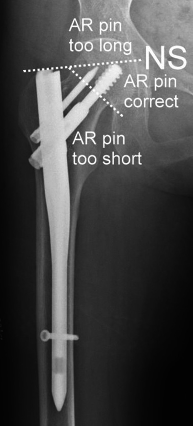
To specify the length of the anti-rotational pin a 3-category-classification using the AR pin tip in the AP view as a reference was used. The pins were considered too short if not reaching the border between femoral head and neck. On the other hand, AR pins crossing an imaginary line between the proximal end of the nail and the tip of the lag screw (NS line) were classified as too long. Any AR pin length in between has been considered as correct (Fig. 1).
Fig. 1.

Classification of AR pin length. AR pins not reaching the femoral head are considered “too short”, whereas AP pins crossing the line between nail tip and lag screw tip (NS line) are regarded “too long”. Any length in between is considered “correct”
Statistical analysis
Statistical analysis included both descriptive and inferential measures. Mean values and standard deviations were calculated for continuous variables, and frequency counts and percentages were obtained for the discrete variables. All confidence intervals (designated “CI”) are 95 % confidence intervals. χ2 test was used for cross tabulation analysis when all expected cell frequencies were five or greater, Fisher’s exact test was used otherwise. For continuous variables (patient age) the two-sample independent t-test was used. Odds ratio was calculated to approximate relative risks. All statistical analyses were performed with IBM SPSS statistics version 19.
Results
Twenty-two patients with hip perforation have been identified. Median time between operation and occurrence of perforation was 47 days (7–883). In 14 of these patients (63.6 %) a typical cut-out mechanism associated with rotation of the proximal fragment was observed. The other eight cases (36.4 %) did not show any evidence of proximal fragment displacement and were therefore categorized as medial perforation (“cut-through”). The patient groups of cut-out and cut-through did not significantly differ for patient age (79.1 vs. 76.5 years; p = 0.6), TAD (24.8 vs. 24.6 mm; p = 0.9), or for fracture type (A1: 14.3 % vs. 12.5 %; A2: 71.4 % vs. 75.0 %; A3: 14.3 vs. 12.5 %).
In the cut-out group the CCD angle of the implant on average was 8° smaller than the postoperative femoral neck CCD (relative valgus position of the bone fragment). However, in patients suffering from a cut-through implant CCD turned out to be about 4° higher than femoral neck CCD (relative varus position of the bone fragment). This difference was significant on t-test (p = 0.03).
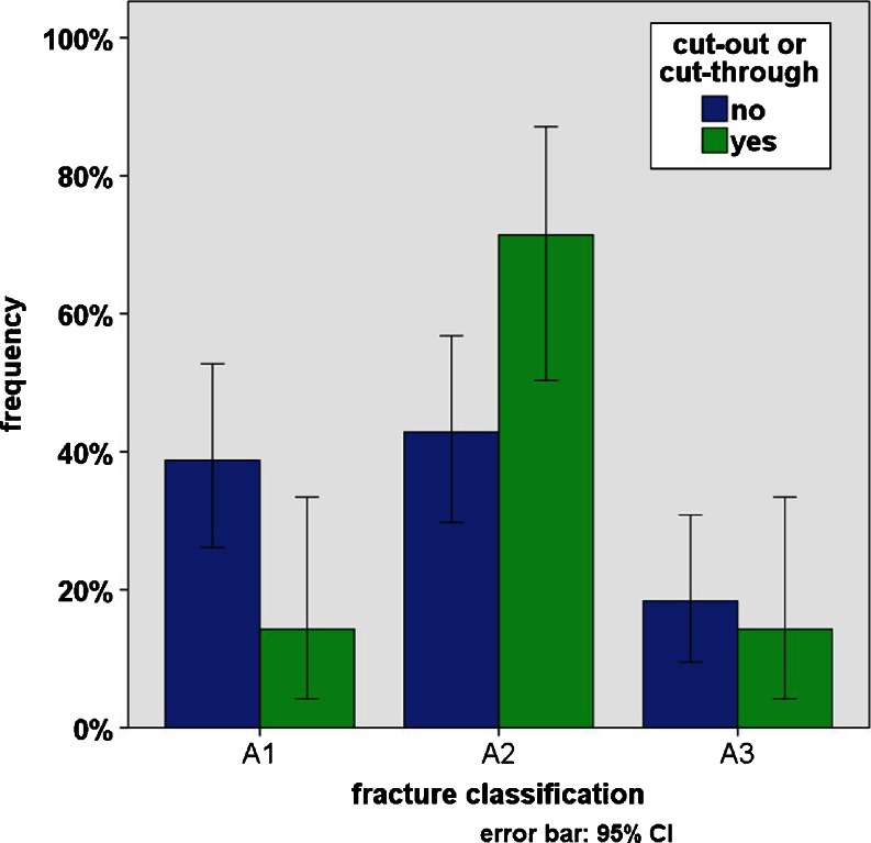
Comparing patients with implant perforation (cases) to patients without complications (controls) the fracture types were unequally distributed (Fig. 2). In the controls we found A1 fractures in 38.8 %, A2 fractures in 42.9 %, and A3 fractures in 18.4 %. The cases however showed A1 fractures in only 14.3 %, A2 fractures in 41.7 %, and A3 fractures in 14.3 %. The association between cut-out/cut-through and the incidence of A1 and A2 fractures was significant on χ2 test (p = 0.025). However, fracture displacement in A1 and A2 fractures was comparable (3.2 mm vs. 3.3 mm), whereas displacement in A3 fractures was higher (7.4 mm).
Fig. 2.
In the control group fracture types A1 and A2 were nearly equally distributed (38% vs. 42%). In cases of cut-out or perforation however fracture type A1 occurred much more seldom than type A2 (14% vs. 68%)
Mean tip–apex distance (TAD) in patients without complication was 20.5 mm (CI 18.4–22.5 mm), but 24.7 mm (CI 20.1–29.3 mm) in cases of implant perforation. This increased TAD was significant on t-test for independent samples (p = 0.048).
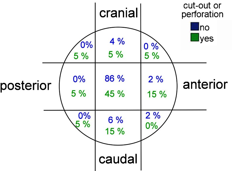
Positioning of the lag screw was central within the femoral head in 86 % of the controls, whereby only 4 % had been placed in the anterior or posterior third and 10 % too cranially or caudally. In patients with implant perforation however only 45 % of the lag screws were placed centrally and 35 % were placed outside the central third of the femoral head (Fig. 3).
Fig. 3.
Lag screw positioning within the femoral head. In patients without complication 86% of the lag screws had been positioned centrally, whereas in cases of cut-out or cut-through this was true only for 45% of the lag screws
Analysing the mean angle deviation between the femoral neck axis and the lag screw axis we found 5.0° in the controls compared to 10.4° in cases of cut-out or cut-through. This difference was significant on t-test (p = 0.001).
Whilst analysing the telescoping capacity allowed by the lag screw (i.e. the “telescrew”) we found a small but significant shorter gliding capacity in the complications group (15.8 mm vs. 18.4 mm; p = 0.02).
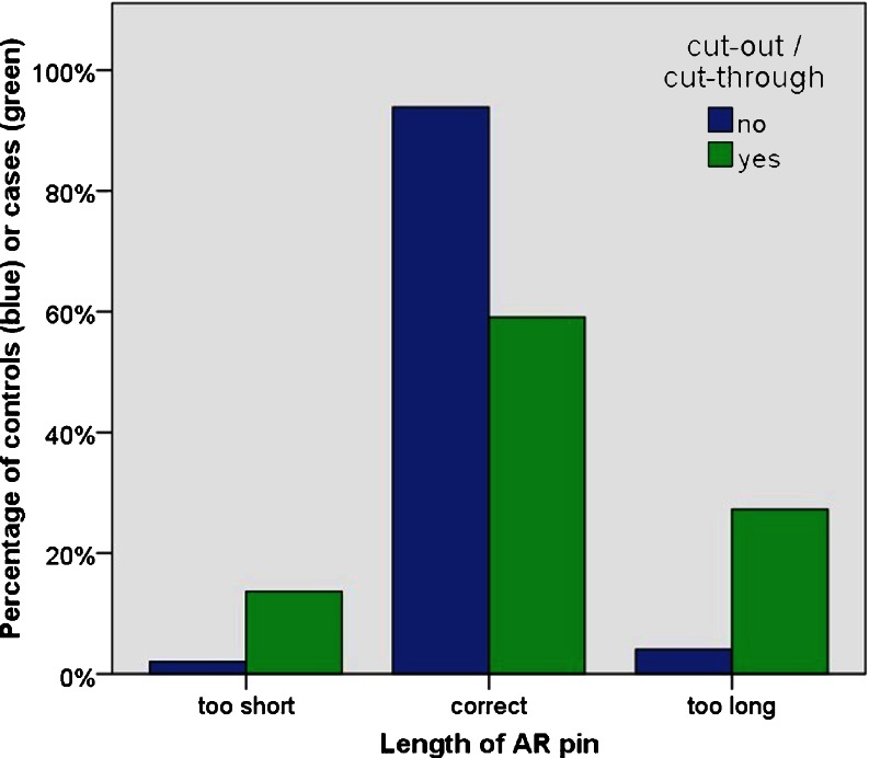
In the control group the length of the anti-rotational pin (AR pin) was correct in 93.9 %. It was too short in 2.0 % and too long (above NS line) in 4.1 %. In patients with implant perforation we found a correct AR pin length in 59.1 %. In 13.6 % the pin was too short and in 27.3 % it was too long, crossing the NS line (Fig. 4). It turned out significantly on Fisher’s exact test that the AR pin exceeding the NS line is associated with an increased frequency of implant perforation (p = 0.009). Testing this association for too short AR pins however we could not achieve the level of statistical significance (p = 0.085).
Fig. 4.
Length of the anti-rotational pin. More than 20% of patients with fixation failure had too long AR pins (exceeding the NS line), while in more than 10% the AR pin was too short. In patients without complication the AR pin was correct in around 90%
Odds ratio was calculated for several risk factors suspected to be associated with the occurrence of implant perforation. The results can be taken form Table 1.
Table 1.
Overview of various risk factors and the respective odds ratio, its 95 % confidence interval and statistical significance
| Risk factor | Odd’s ratio | 95 % CI of odds ratio | p-value |
|---|---|---|---|
| Fracture type A1 | 0.3 | 0.1–1.0 | 0.04 a |
| Fracture type A2 | 3.3 | 1.1–10.0 | 0.03 a |
| Fracture type A3 | 0.7 | 0.2–3.1 | 0.68 a |
| Tip–apex distance > 20 mm | 1.9 | 0.7–5.3 | 0.22 a |
| Lag screw positioned in anterior or posterior third of femoral head | 5.5 | 0.5–65.0 | 0.19 b |
| Lag screw positioned in cranial third of the femoral head | 2.5 | 0.5–13.4 | 0.28 b |
| Angle deviation between femoral neck axis and lag screw > 10° | 6.5 | 1.8–23.9 | 0.005 b |
| Gliding distance of telescrew ≤15 mm | 4.2 | 1.2–14.3 | 0.024 b |
| Displacement >5 mm | 1.5 | 0.5–4.8 | 0.46 a |
| AR-Pin too short | 7.7 | 0.76–79.1 | 0.082 b |
| AR pin too long | 8.8 | 1.6–48.1 | 0.009 b |
| AR pin too short or too long | 10.8 | 2.6–46.0 | 0.001 b |
Reference for the odds ratios were all cases without the respective risk factor. In the biaxial fixation system AR pin length seemed to have the greatest association with cut-out and cut-through
a Chi squared test
b Fisher’s exact test
Discussion
Currently accepted predictors for screw cut-out
Several factors supposed to predispose for cut-out are described in the literature or may be assumed by surgical experience [5]. These include circumstances as fracture type (classification), patient age, patient body weight, or bone quality [6]. Other factors however may be influenced by the operation. Commonly accepted operative predictors for fixation failure are quality of reduction, tip apex distance (TAD), and lag screw position within the femoral head and neck [7, 8].
Fracture classification has recently been shown to be an important predictor for cut-out; for comparison of fracture category A3 to category A1 an odds ratio of 3.32 was reported [7]. The measurement of the tip–apex distance had been described more than 15 years ago [3]. A recent study reported a mean TAD of 25.9 mm in cut-out patients compared to 21.3 mm in non-cut-out patients [7]. According to Cleveland’s zones of the femoral head [4] the inferior lag screw position seems favourable; a recently reported odds ratio for central-inferior and anterior-inferior positions compared to anterior-superior positions is 0.11 [7]. The same authors saw no cut-out after posterior-inferior lag screw placement.
Implant design and cut-out prevention
Implant manufacturers nowadays have developed different designs meant to prevent the proximal fragment from rotation and to avoid central head perforation (cut through). These designs may be monoaxial or biaxial. Recent developments of monoaxial systems include special lag screw designs (Gamma3, Stryker), femoral head fixation by certain profiles (Gliding Nail, Smith&Nephew), helical blades and the option for cement augmentation (PFNA Augmentation, Synthes). Even with the latest monoaxial fixation system the problem of implant perforation is still not resolved [9].
Currently available biaxial fixation systems include nails with two lag screws (Expert Lateral Femoral Nail, Synthes), with intercalated lag screws (Trigen Intertan, Smith&Nephew), and with the use of anti-rotational pins (Platon, Tantum or Targon PF/PFT, Aesculap).
There are only few publications dealing with the biomechanics of biaxial fixation systems. However in 2009 a finite element analysis three monoaxial systems (PFN-A, Gamma-Nail, Gliding Nail) were compared to a biaxial system (Targon PF) with regard to distributions of stress and strain on the fracture surfaces, investigating both cranial and caudal implant positions. The authors reported that only the biaxial system demonstrated better fracture healing conditions in a cranial position and some advantages in the caudal position [10]. However there still is a complete lack of clinical studies investigating predictors for cut-out and cut-through in biaxial systems.
Influence of fracture classification, TAD, and lag screw positioning in biaxial systems
Examining the Targon PF/PFT we can confirm recently published results on the association between fracture classification and fixation failure. Compared to fracture types A1 and A3 we found an odds ratio of 3.3 for A2 fractures, which was clearly significant. An odds ratio of 0.3 for A1 fractures on the other hand confirms the low relative risk for that collective. For A3 fractures however we could not confirm the high risk reported by de Bruijn et al. [7], since we did not observe statistical significance. One might hypothesize that biaxial nail systems might be more protective in A3 fractures.
For TAD and lag screw positioning1 we found odds ratios indicating an increased cut-out risk for higher TAD as well as for cranial, anterior or posterior lag screw positions (Table 1); however, we did not reach the level of statistical significance. By tendency these clinical findings contradict the finite elements results of Helwig et al. [10], who reported advantages for the Targon PF in cranial positions.
Remarkably we found significantly increased odds ratios for axis deviation between femoral neck and lag screw >10° in the axial view (implant perforation increased by 6.5) and for lag screw gliding capacities ≤15 mm (implant increased by 4.2). Further investigation should be undertaken to explore if in biaxial proximal femoral nails these measurements might be better predictors for cut-out than TAD or lag-screw position classified by Cleveland’s system [4].
The length of the anti-rotational pin predicts fixation failure
Measurements of the anti-rotational (AR) pin length are specific for biaxial fixation systems. No association between AR pin length and cut-out has been reported so far. We introduce a simple three-category classification for AR pin length. Pins were considered too short if not reaching the border between femoral head and neck. On the other hand AR pins crossing an imaginary line between the proximal end of the nail and the tip of the lag screw (NS line) are classified as too long. Any AR pin length in between is considered correct. For AR pins that are too long, our investigation revealed an odds ratio of 8.8 (p = 0.009) for fixation failure. Comparing AR pins which are either too long or too short we found a 10.8-fold increased risk for cut-out or cut-through (p = 0.001). The association between AR pin length and fixation failure found in our examination exceeds those of all other factors studied by far. It must be suspected that AR pin length might be the most relevant measurement influencing the risk for implant perforation in biaxial proximal femoral nails.
Limitations and prospects
A good hold of the implant within the femoral head certainly will be protective against fixation failure. However recent literature suggests that cut-out and cut-through might be different entities with different underlying biomechanics [9]. Blocking proximal fragment rotation might prevent cut-out whereas easy telescoping may protect against cut-through [11]. Like other studies [7, 12], we could not separate any predictors for cut-out and cut-through. Comparing the CCD angle of the implant to that of the femoral neck after reconstruction we found the lag screw to be 8° more varus in the cases of cut-out, but 4° more valgus in the cases of cut-through. The difference was significant. The findings suggest that both low implant CCD angles and valgus reduction might predispose for cut-out whereas high implant CCD angles and varus reduction will abet cut-through. However larger studies are needed to further explore the differences between cut-out and cut-through.
To our knowledge this is the first study clinically investigating predictors for implant perforation in a biaxial proximal femoral nail. The Targon nail, which was used for this study, is one of the more contemporary intramedullary nails, showing some unique features. These include a proximal fixation with a screw and sleeve system (Targon PF) or a Telescrew (Targon PFT). Both systems offer a reduced risk of jamming of the sliding mechanism [11]. The unique design of the Targon nail complicates the transfer of our results to other biaxial systems. Therefore similar studies using other biaxial implants are desirable in order to confirm our results.
Conclusions
Fixation failure after proximal femoral nailing still remains a major problem. Recent literature suggests that cut-out and cut-through might be two different biomechanical processes that cause implant perforation into the hip joint, which is a devastating complication.
We investigated risk factors for implant perforation in the Targon PF/PFT, which is a biaxial proximal femoral nail. Consistent with the literature, fracture type could be confirmed as a risk factor. For other commonly accepted risk factors (tip–apex distance, lag screw position) however we did not find clearly significant associations with cut-out.
Length of the anti-rotational pin was found to play a crucial role for predicting cut-out and cut-through. A simple three-category classification system was developed in order to help in choosing an adequate length of this element.
Acknowledgments
Conflict of interest
RB and HJB have received grants from B. Braun Aesculap (Tuttlingen, Germany) within the last five years. BZ declares that she has no conflict of interest.
Footnotes
in Targon PFT terminology: telescrew positioning
Birgit Zirngibl and Roland Biber contributed equally to this work.
Contributor Information
Birgit Zirngibl, Email: birgit.zirngibl@klinikum-nuernberg.de.
Roland Biber, Phone: +49-911-3982600, Email: biber@klinikum-nuernberg.de.
Hermann Josef Bail, Email: hermann-josef.bail@klinikum-nuernberg.de.
References
- 1.Schipper IB, Bresina S, Wahl D, Linke B, Van Vugt AB, Schneider E. Biomechanical evaluation of the proximal femoral nail. Clin Orthop Relat Res. 2002;405:277–286. doi: 10.1097/00003086-200212000-00035. [DOI] [PubMed] [Google Scholar]
- 2.Heinert G, Parker MJ. Intramedullary osteosynthesis of complex proximal femoral fractures with the Targon PF nail. Injury. 2007;38:1294–1299. doi: 10.1016/j.injury.2007.05.010. [DOI] [PubMed] [Google Scholar]
- 3.Baumgaertner MR, Curtin SL, Lindskog DM, Keggi JM. The value of the tip-apex distance in predicting failure of fixation of peritrochanteric fractures of the hip. J Bone Joint Surg Am. 1995;77:1058–1064. doi: 10.2106/00004623-199507000-00012. [DOI] [PubMed] [Google Scholar]
- 4.Cleveland M, Bosworth DM, Thompson FR, Wilson HJ, Jr, Ishizuka T. A ten-year analysis of intertrochanteric fractures of the femur. J Bone Joint Surg Am. 1959;41:1399–1408. [PubMed] [Google Scholar]
- 5.Hsueh KK, Fang CK, Chen CM, Su YP, Wu HF, Chiu FY. Risk factors in cutout of sliding hip screw in intertrochanteric fractures: an evaluation of 937 patients. Int Orthop. 2010;34:1273–1276. doi: 10.1007/s00264-009-0866-2. [DOI] [PMC free article] [PubMed] [Google Scholar]
- 6.Bonnaire F, Weber A, Bösl O, Eckhardt C, Schwieger K, Linke B. “Cutting out” in pertrochanteric fractures—problem of osteoporosis? Unfallchirurg. 2007;110:425–432. doi: 10.1007/s00113-007-1248-0. [DOI] [PubMed] [Google Scholar]
- 7.De Bruijn K, den Hartog D, Tuinebreijer W, Roukema G. Reliability of predictors for screw cutout in intertrochanteric hip fractures. J Bone Joint Surg Am. 2012;94:1266–1272. doi: 10.2106/JBJS.K.00357. [DOI] [PubMed] [Google Scholar]
- 8.Kawaguchi S, Sawada K, Nabeta Y. Cutting-out of the lag screw after internal fixation with the Asiatic gamma nail. Injury. 1998;29:47–53. doi: 10.1016/S0020-1383(97)00158-7. [DOI] [PubMed] [Google Scholar]
- 9.Frei HC, Hotz T, Cadosch D, Rudin M, Käch K. Central head perforation, or “cut through”, caused by the helical blade of the proximal femoral nail antirotation. J Orthop Trauma. 2012;26:e102–e107. doi: 10.1097/BOT.0b013e31822c53c1. [DOI] [PubMed] [Google Scholar]
- 10.Helwig P, Faust G, Hindenlang U, Hirschmüller A, Konstantinidis L, Bahrs C, Südkamp N, Schneider R. Finite element analysis of four different implants inserted in different positions to stabilize an idealized trochanteric femoral fracture. Injury. 2009;40:288–295. doi: 10.1016/j.injury.2008.08.016. [DOI] [PubMed] [Google Scholar]
- 11.Parker MJ, Bowers TR, Pryor GA. Sliding hip screw versus the Targon PF nail in the treatment of trochanteric fractures of the hip. J Bone Joint Surg Br. 2012;94:391–397. doi: 10.1302/0301-620X.94B3.28406. [DOI] [PubMed] [Google Scholar]
- 12.Kawatani Y, Nishida K, Anraku Y, Kunitake K, Tsutsumi Y. Clinical results of trochanteric fractures treated with the TARGON® proximal femur intramedullary nailing fixation system. Injury. 2011;42(S4):22–27. doi: 10.1016/S0020-1383(11)70008-0. [DOI] [PubMed] [Google Scholar]


