

Abstract
Experimental tests and computational modeling were used to explore the fluid dynamics at the trabeculae-cement interlock regions found in the tibial component of total knee replacements (TKR). A cement-bone construct of the proximal tibia was created to simulate the immediate post-operative condition. Gap distributions along nine trabeculae-cement regions ranged from 0 to 50.4µm (mean=12 µm). Micro-motions ranged from 0.56 to 4.7µm with a 1 MPa compressive load to the cement. Fluid-structure analysis between trabeculae and cement used idealized models with parametric evaluation of loading direction, gap closing fraction, gap thickness, loading frequency, and fluid viscosity. The highest fluid shear stresses (926 Pa) along the trabecular surface were found for conditions with very thin gaps and large closing fractions; much larger than reported physiological levels (~ 1–5 Pa). A second fluid-structure model was created with provision for bone resorption using a constitutive model with resorption velocity proportional to fluid shear rate. A lower cut-off was used, below which bone resorption would not occur (50 1/s). Results showed that there was initially high shear rates (> 1000 1/s) that diminished after initial trabecular resorption. Resorption continued in high shear rate regions, resulting in a final shape with bone left deep in the cement layer, and is consistent with morphology found in postmortem retrievals. Small gaps between the trabecular surface and cement in the immediate post-operative state, produce fluid flow conditions that appear to be supra-physiologic; these may cause fluid induced lysis of trabeculae in the micro-interlock regions.
1. Introduction
Approximately 600,000 total knee replacements (TKR) are performed each year in the United States [1] and the number of joint replacements is expected to rise dramatically to over 3 million/yr by 2030 [2]. TKR is a very successful procedure with substantial improvement in patient functional status and quality of life. Most patients (85%) are satisfied with the results of surgery [3]. For patients that require a revision, aseptic loosening is the leading cause, with an 8-year revision rate of 5% [4, 5] based on total joint registry data. For patients 55 or younger, the revision rate increases dramatically to 11% at 8 years [6]. This is of particular concern because 50% of primary TKR will be performed in patients under 65 within the next few years [7]. Also of concern is the fact that the ratio of the number of revision to primary arthroplasties, or revision burden, does not appear to be decreasing with time [8]. Substantial efforts have been made to improve function of knee replacements, particularly with regards to knee kinematics, surgical alignment, and development of new bearing couples. One area that has received much less attention is the mechanism of loss of fixation of cemented TKR with in-vivo service. Avenues to understand how the loosening process occurs could lead to new approaches to improve short and long term survival of cemented TKR.
A recent study of postmortem-retrieved total knee replacements shows that there is loss of micro-interlock at the cement-bone interface and this occurs by resorption of the trabeculae that were initially embedded in the cement layer [9]. The pattern of bone resorption is not uniform, and occurs preferentially at the extent of penetration of the cement layer into the bone, at times leaving fragments of bone deep in the cement (Figure 1). Loss of strength of the cement-bone interface with time of in-vivo service has been documented for tibial trays of total knee replacements [10]. Loss of interface stiffness, manifested as increased micro-motion, has also been measured in cemented hip replacements following in vivo service[11]. It would be reasonable to expect that the loss of fixation is related to loss of strength and stiffness following in-vivo service.
Figure 1.
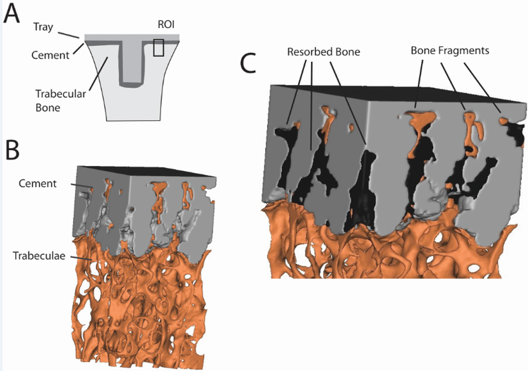
Cement-bone specimen taken from a region of interest (ROI) on the underside of the en bloc retrieved tibial tray (A) showing trabeculae interlocked with cement (B). Spaces left by the resorbed bone are evident (C) and are filled to improve clarity. Bone fragments away from the trabecular bone bed are noted.
The mechanism of loss of trabeculae-cement interlock is not known, but in previous experiments in which cement-bone constructs were mechanically loaded [12], we noted efflux and influx of fluid at the trabeculae-cement interface. High fluid flow magnitudes (20 mm/s) and pressures (53000 Pa) have been shown to cause osteolysis in the absence of debris [13]. It is possible that encasing the trabeculae with cement could result in a state of supra-physiologic fluid flow when the joint replacement is loaded, and that this in turn could cause a local osteolytic response. Because it is extremely difficult to quantify the local fluid flow experimentally for very small length scales (tens of microns), we propose to use finite element modeling capabilities that account for fluid-structure interactions at the level of the trabeculae-cement interface.
The goals of this research project were to (1) experimentally quantify the presence of interface gaps and micro-motion between trabeculae and cement, (2) determine morphologic and loading conditions that cause high fluid velocity, pressure, and shear stress at the trabecula/cement interface, that could be responsible for trabecular osteolysis, (3) determine ‘homeostatic’ shear rate/stress levels at the bone surface using fluid dynamic simulations of postmortem cement-bone constructs, and (4) implement a bone surface resorption algorithm using information gained from Goal 3 to determine if the resorption pattern found in trabeculae-cement regions is consistent with postmortem retrievals.
2. Methods
A combination of experimental tests and computational modeling was used to explore the fluid dynamics at the trabeculae-cement interface found in the tibial component of total knee replacements (TKR). There is no existing experimental data on the micro-level morphology of the trabeculae-cement interface from TKR and no measures regarding how much these interfaces move when loaded. This is addressed in Section 2.1. Using this experimental data, idealized trabeculae-fluid-cement multi-physics analyses are performed using a parametric modeling approach in Section 2.2, to determine morphologic and environmental factors that contribute to high fluid flow and pressure. This data is also compared to existing literature on the response of cells or animal models to physiologic and supra-physiologic flow rates. In section 2.3, the concept of a ‘homeostatic’ fluid shear rate level on bone adjacent to the cement mantle is explored by modeling fluid flow of well-fixed postmortem retrieved hip replacements that were functionally loaded in a previous laboratory investigation. Data from these models could provide information as to fluid shear rate or stress magnitudes are present in functioning joint replacements. Corresponding experimental data does not exist yet for postmortem knee replacements, but it would be reasonable to anticipate that the biological response to bone to fluid flow would be similar for the hip and knee. Finally, in section 2.4 the load-induced fluid flow around a representative trabeculae-fluid-cement construct was determined and a bone surface resorption algorithm was applied using the information generated in Section 2.3.
2.1 Experimental Gap Distribution and Micro-motion for the Immediate Post-operative Condition
A laboratory-prepared cement-bone construct of the proximal tibia was created to simulate the immediate post-operative condition using an approach that would be representative of clinical practice. A proximal cadaveric tibia (51 year old male, 118 kg, 188 cm) from the SUNY Upstate Anatomical Gift Program was cut in the transverse plane, cleaned using pulsatile lavage and warmed to 37 deg C in a blood analogue solution. Polymethyl-methacrylate cement (PMMA, Simplex, Stryker Orthopaedics, Mahwah, NJ) was hand mixed and applied to the cut bone surface in a doughy state. A plastic spatula was used to press the cement into the trabecular bone bed and a metal tray was pressed onto the cement surface. A tibial tray component was not used for this laboratory preparation because the trabeculae-cement interface was of interest rather than the whole construct. A segment of the cement-bone interface was cut using an irrigated silicon carbide blade to produce a small specimen with 8x8mm cross section. The cut trabeculae-cement surface was polished and high resolution reflected white light microscopy (1.3 µm/pixel) was used to document the morphology along the trabeculae-cement interface (Figure 2).
Figure 2.
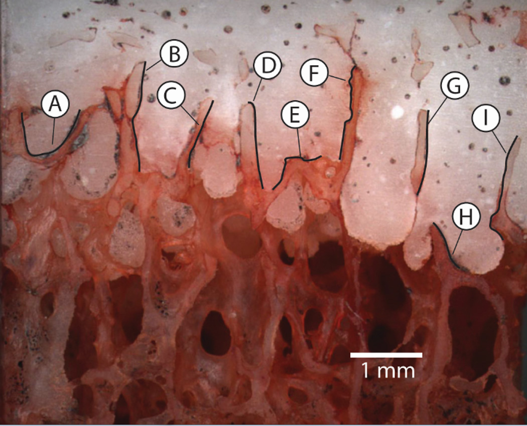
The trabeculae-cement interlock region from the proximal tibia from a laboratory prepared specimen. Gap thickness and micro-motion measurements were made at 9 regions along the interface. The black trace lines represent the regions where gap/micro-motion measurements were made. Regions E and F were used as the basis for the modeling effort in Section 2.4.
The specimen was prepared for mechanical loading by first adding optical texture to the surface using acrylic spray paint. The specimen was then attached to a mechanical test frame and loaded in axial compression to 1.0 MPa using displacement control (2 mm/min). Loading consisted of three pre-conditioning cycles (0.02 MPa tension to 1 MPa compression), followed by image collection (1.8 µm/pixel) during the fourth cycle at 4 Hz. Digital Image Correlation (DIC, Rapid-Correlator, Xstream Software, Ottawa, Ontario, Canada) was used at pairs of sampling points on each side of the trabeculae-cement interface to document micro-motion (Figure 2). The sampling pairs were spaced at approximately 200 µm intervals along the regions of interest and the total micro-motion and shear and normal motion components were calculated.
2.2 An Idealized Trabeculae/Fluid/Cement Computational Model
An idealized trabeculae-fluid-cement mesh (Figure 3A) was created based on the experimental data (Section 2.1). The 2-D plane strain model included fluid-structure interactions because the bone (E=17 GPa, ν=0.3, ρ=1850 kg/m^3) and cement (E=3 GPa, ν =0.3, ρ=1200 kg/m^3) were deformable structures that interacted with the fluid when loaded. The fluid component was either water (µ = 0.001 Pa-s, ρ=1000 kg/m^3) or marrow [14] (µ=0.1 Pa-s, ρ =1250 kg/m^3) and was considered to be newtonian and incompressible. The Reynolds number was estimated to be consistent with laminar flow conditions; a maximum of Re=0.42 for water with 14 mm/s flow rate and a 0.03 mm gap, assuming annular flow.
Figure 3.
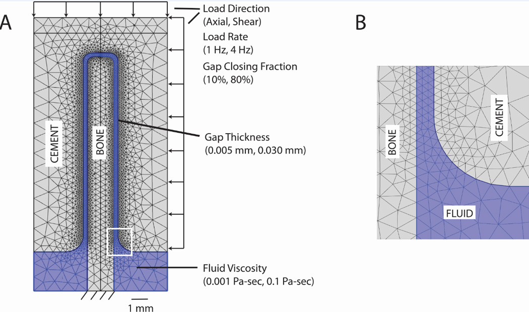
Idealized trabecula-cement-fluid model (A) showing parameter levels. Inset image (B) shows detail of the fluid gap finite element density.
Finite element meshes were constructed such that there were at least 3 elements spanning the fluid filled gap between cement and bone (Figure 3B). Models with thinner gaps required more total elements (Table 1) because of local mesh refinement at the interface. The solid triangular elements used a second order (quadratic) formulation, with six nodes per element. The fluid used Lagrange P2-P1 triangular elements [15]. That is, second order (quadratic) elements were used for the velocity components, while linear elements were used to model the pressure. As the simulation assumes that the fluid is incompressible, it is important to note that the P2-P1 fluid formulation satisfies the Ladyzenskaja-Babuska-Brezzi (LBB) condition [16].
Table 1.
Characteristics of the fluid/structure models including element count, total degrees of freedom, typical time steps to completion, and applied load type.
| Idealized Parametric Model (30 µm gap) |
Idealized Parametric Model (5 µm gap) |
Torsionally Loaded Cemented Hip Cross Section |
Representative Cement- Trabeculae Construct |
|
|---|---|---|---|---|
| Method Section | 2.2 | 2.2 | 2.3 | 2.4 |
| Fluid elements | 2200 | 8700 | 18900 | 4900 |
| Cement elements |
4400 | 18100 | 29100 | 5900 |
| Bone elements | 2900 | 15600 | -- | 5500 |
| Degrees of Freedom |
35000 | 227000 | 183800 | 94000 |
| Time steps | 35 – 105 | 60–105 | 25 – 30 | 100 |
| Applied load type | Displacement control |
Displacement control |
Displacement control |
Load control |
Fluid-structure interactions (FSI) analyses (COMSOL, Burlington, MA) used an arbitrary Lagrangian-Eulerian (ALE) approach [17] with fluid flow using an Eulerian description and solid mechanics formulated using a Lagrangian description. A time dependent, monolithic, two-way, fully coupled approach was used in COMSOL for the FSI simulation. The coupling is defined along the FSI boundary with no-slip boundary conditions for the fluid such that the velocity of the fluid (vf) is equal to velocity of the solid moving wall (vw). In addition, the stresses across the fluid-structure interface are in equilibrium.
A fully coupled non-linear solver used a damped version of Newton’s method (damping factor of 1) with time stepping determined automatically using a backward differentiation formula (BDF). A direct solver (PARDISO) was used for all models with RAM storage use of less than 2 GB. Five iterations were allowed per time step; if convergence was not achieved, the time step was automatically reduced and repeated. The initial time step was set to 0.001 s, although this could be reduced with the auto time-step function of the solver.
The trabecular bone was fixed at the base. The bone and cement material interfaces were impermeable to fluid flow and there were no-slip boundary conditions between the fluid and solid elements. There was an open boundary for fluid flow at the bottom of the model with fluid pressure set to zero. The model was loaded using ‘displacement control’, in the axial or shear directions (Figure 3A), by moving the cement relative to the bone using a sinusoidal loading pattern. A phase shift of -π/2 was used so that initially ramping of displacement would be gradual (see example in Figure 6). This facilitated solution convergence at the initial time steps.
Figure 6.
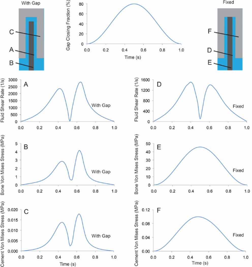
Fluid shear rate, bone von Mises stress, and cement von Mises stress for case with a 30 µm gap and shear loading (0.8 GCF). Cases with a full gap (left column) and fixed between the cement and bone (right column) are shown.
A full factorial design of experiments (DOE) approach [18] was used to explore the effect of loading direction (axial or shear), fluid viscosity (water or marrow), gap thickness (5 µm or 30 µm), gap closing fraction (10% or 80% of the gap thickness), and loading rate (1 Hz or 4 Hz). The viscosity of the fluid in the gaps is not known; water and marrow were chosen to span possible viscosity magnitudes. The choice of gap thickness and closing fraction were made to span the experimental measurements made in Section 2.1. Loading rate would represent conditions possible in active gait (0.125 s to peak load) or much slower loading (0.5 s to peak load). A total of 32 (25) runs were completed. Outcome measures included maximum fluid shear stress at the bone surface, fluid velocity, and fluid pressure in the gap. Shear stress was calculated as the product of shear rate and fluid viscosity.
Additional studies in support of this approach included a mesh refinement (sensitivity) study, assessment of number of loading cycles on fluid-structure response, and the effect of fixing the trabecula to the cement over a segment of the structure.
2.3 Fluid Flow Modeling of Torsionally Loaded Cement-Bone Constructs From Retrieved Hip Replacements
There is evidence that the cement-bone interface for cemented hip replacements is not bonded during in-vivo service and that functional loading of these interfaces causes interface micro-motion [11, 19]. Note that comparable data is not available for knee replacements. The small gaps that form at the interfaces are typically not filled with soft tissue (unless there is very large motion) and are likely filled with fluid. We propose here to simulate the fluid flow response to loading at the cement-bone interfaces of postmortem retrieved hip replacements. The goal is to estimate fluid flow magnitudes that may exist along the bone surface during normal in-vivo conditions. In a previous experiment, 10mm transverse sections from 11 post-mortem retrieved hip replacements (Table 2) were loaded in torsion and the micro-motion between the cement and cortical bone was measured [11]. Idealized multi-physics (fluid/structure) finite element models (COMSOL) were created for each case using the major and minor dimensions of the transverse sections and the median thickness of the cement-bone gap. An elliptical shape was assumed for the cement cross section. A gap around the cement was created with uniform thickness and was assigned saline properties (0.001 Pa-s viscosity). The outside of the fluid gap was fixed as a rigid wall. This was considered a reasonable first estimate of the cortical bone response as induced fluid pressures were very small in comparison to stiffness of the cortical bone ring surround the cement. Typical model characteristics are shown in Table 1. The cement was displaced in the models (relative to the bone) using the experimentally determined normal and shear micro-motions as input (Table 2). The induced fluid flow was simulated during the loading cycle (1 Hz) and the maximum shear rate along the wall of the bone was calculated.
Table 2.
The micro-motion and gap thickness of the cement-bone interface from 11 post-mortem retrieved hip replacements was determined previously in an experimental investigation* [11]. This data was used as input into idealized fluid/structure finite element models to determine maximum fluid velocity, pressure, and shear rate.
| Experimental Data* | Fluid Flow Model Results | |||||||
|---|---|---|---|---|---|---|---|---|
| Donor | Median Interface Gap Thickness (mm) |
Median Inteface Shear Micro- motion (mm) |
Median Interface Normal Micro- motion (mm) |
Cement Mantle Minor Dimension (mm) |
Cement Mantle Major Dimension (mm) |
Velocity (mm/s) |
Pressure (Pa) |
Shear Rate (1/s) |
| A | 0.068 | 0.0041 | 0.0011 | 18.0 | 18.1 | 0.71 | 21.82 | 32.29 |
| B | 0.170 | 0.0057 | 0.0010 | 18.7 | 18.9 | 0.27 | 1.39 | 5.13 |
| C | 0.182 | 0.0221 | 0.0110 | 17.7 | 17.8 | 2.61 | 11.14 | 44.66 |
| D | 0.170 | 0.0264 | 0.0076 | 17.9 | 21.8 | 2.57 | 11.39 | 46.82 |
| E | 0.136 | 0.0035 | 0.0014 | 15.2 | 19.2 | 0.48 | 3.02 | 10.98 |
| F | 0.136 | 0.0033 | 0.0021 | 16.3 | 22.4 | 0.75 | 5.56 | 16.93 |
| G | 0.045 | 0.0031 | 0.0009 | 16.9 | 17.0 | 0.82 | 54.16 | 56.21 |
| H | 0.318 | 0.1656 | 0.0410 | 17.9 | 18.9 | 6.45 | 8.46 | 61.56 |
| I | 0.193 | 0.0331 | 0.0161 | 14.8 | 20.5 | 3.93 | 12.69 | 63.00 |
| J | 0.568 | 0.6940 | 0.1478 | 17.8 | 20.1 | 15.70 | 6.48 | 79.09 |
| K | 0.079 | 0.0019 | 0.0007 | 18.0 | 20.5 | 0.45 | 9.75 | 17.36 |
2.4 Simulating Fluid Flow Around Representative Cement-Trabecular Bone Construct
A recent retrieval study [9] suggests that there is focal loss of trabecular bone (Figure 1) during in-vivo service of the cement-bone interlock region. To investigate the fluid flow and possible fluid driven resorption mechanism, a 2D plane strain mesh was created for a small segment of the trabeculae-cement interface (Section 2.1) with an initial 15 µm fluid gap between the cement and bone (Figure 4a). As was used in Section 2.2, a multiphysics simulation (COMSOL) was performed including fluid-structure interactions where the cement and bone were deformable structures and the fluid behaved in a laminar flow regime. Typical model characteristics are shown in Table 1. A cyclic (1 Hz) 1 MPa axial load with small transverse component (0.02 MPa) was applied to the top of the cement; this induced fluid flow within the gap and load transfer to trabeculae. The trabeculae were fixed below. Note that the top of the trabecula was fixed to the cement in this simulation. In contrast to the previous models, this model was loaded in ‘load control’ with applied forces in place of displacements. This approach was chosen because it would be more likely to result in an increase in micro-motion when coupled to a bone resorption process. A displacement control loading case (where micro-motion was fixed) would likely cause reduced fluid shear as the bone resorption process progressed. Further, if the trabecula were not attached to the bone, a ‘load control’ scenario could not be used, as physically the cement would collide with the bone. A Newtonian (water) fluid layer (µ = 0.001 Pa-s) was assumed. Boundary conditions were the same as those applied in Section 2.2.
Figure 4.
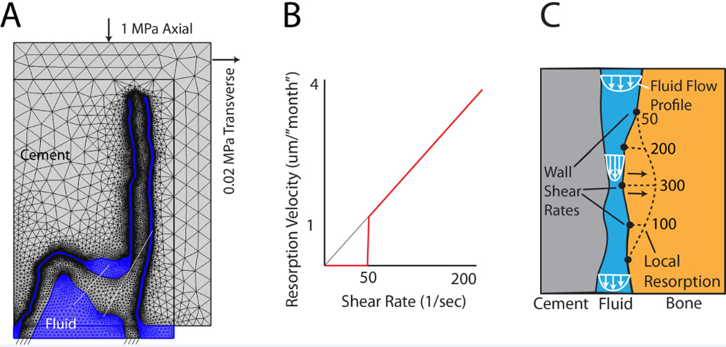
Structure-fluid mesh (A) of the trabeculae-cement interface was loaded axially (1 MPa) with a small (0.02 MPa) transverse load. A resorption algorithm (B) with 50 1/s shear rate cut-off was used to define resorption velocity of the bone (C). Resorption, shown as a dotted line, was proportional to shear rate (example numbers shown).
To simulate the resorption process at the trabecular surface, we used the ‘homeostatic’ shear rate values (~50/s) calculated from Section 3.3 results as a cut off level, below which resorption would not occur. This served as the basis for a bone surface resorption algorithm (Figure 4b). We assumed that for shear rates > 50/s, resorption rate (surface velocity) was proportional to the shear rate. In this way, regions with higher shear rates (Figure 4c) would result in higher rates of bone loss (as has been observed experimentally in a rat model [4]). The resorption rate was chosen such that there was a substantial loss of bone in 18 ‘months’. This was chosen because we have found substantial loss of trabecular bone in this short time period (1–2 years) in retrievals [20]. The algorithm was adapted to successive COMSOL fluid dynamic simulations for each time step (indicated here as a virtual ‘month’) by resorbing bone at a rate (Figure 4c) proportional to local fluid shear rate, remeshing, and continuing the fluid-structure simulation. Simulations were stopped just prior to the point where the cement would come into contact with the bone. In our simulation approach, wall-wall contact could not be simulated.
3. Results
3.1 Experimental Gaps and Micro-motion
Mean gap thickness ranged from 5.3 to 20.2 µm (Table 3) for the nine sampling regions. The minimum gap thickness was 0 µm (direct apposition) and the largest gap was 50.4 µm. There were areas of direct apposition in all sampling regions. Mean micro-motions for the 9 regions with a 1 MPa compressive load ranged from 0.56 µm to 4.71 µm. The smallest micro-motion was 0.1 µm and largest was 5.5 µm. The majority of the sampling regions had more shear motion compared to normal (opening or closing) motion. Notable exceptions were sample regions A and H where there was more closing motion than shear, as would be expected because these interface regions were orthogonal to the loading direction. It is also interesting to note that we could observe fluid pumping in and out of the trabeculae-cement interfaces when loading. This provides further evidence that the interfaces are not bonded and that fluid is likely to occupy these small gaps in-vivo.
Table 3.
Trabeculae-cement interface gap thickness and micro-motion for a laboratory prepared construct.
| Region | Gap Thickness (µm) | Micro-Motion (µm) | |||||||
|---|---|---|---|---|---|---|---|---|---|
| Mean | S.D. | Min | Max | Mean | S.D. | Min | Max | Shear/normal ratio |
|
| A | 20.23 | 14.12 | 0 | 50.4 | 0.56 | 0.44 | 0.12 | 1.39 | 0.90 |
| B | 15.40 | 10.71 | 0 | 42 | 0.96 | 0.41 | 0.26 | 1.54 | 1.49 |
| C | 11.83 | 10.15 | 0 | 37.2 | 0.67 | 0.32 | 0.10 | 1.06 | 2.57 |
| D | 5.34 | 2.89 | 0 | 13.2 | 1.13 | 0.38 | 0.64 | 1.83 | 1.17 |
| E | 15.36 | 13.42 | 0 | 50.4 | 1.37 | 0.43 | 1.04 | 1.99 | 1.99 |
| F | 6.32 | 2.55 | 0 | 13.2 | 1.68 | 0.17 | 1.48 | 1.94 | 3.62 |
| G | 5.76 | 5.10 | 0 | 18 | 0.78 | 0.26 | 0.41 | 1.06 | 1.13 |
| H | 17.25 | 6.66 | 0 | 33.6 | 4.71 | 0.79 | 3.80 | 5.46 | 0.29 |
| I | 8.95 | 6.03 | 0 | 25.2 | 1.71 | 0.93 | 0.62 | 3.47 | 1.53 |
3.2 Idealized Fluid Flow Around Trabeculae
Axial loading (Figure 5A) resulted in a near uniform fluid velocity along the interface gap and highest pressure near the top of the trabecula. Results are shown here at t=0.25s for a 30 µm gap with 80% gap closing fraction, loading frequency of 1 Hz, 0.1 Pa-s fluid viscosity. For the shear loading case (Figure 5B), there was an asymmetric response with fluid egress on the right side of the bone and ingress on the left side during the loading phase, followed by a reversal during the unloading phase. The highest fluid velocity and shear rate during the loading phase was near the bottom right segment of the interface. The highest fluid pressure during loading in shear was along the mid-body of the trabecula. Peak magnitudes occurred at approximately 0.6 s of the 1 s loading cycle (Figure 6A). The bone von Mises stresses were small (4 MPa) and greatest near the fixed base and were in phase with the fluid shear loading (Figure 6B). Cement stresses were very small (Figure 6C). Note that the shape of the fluid shear rate versus time response varied greatly depending on geometry and loading parameters. For example, with the same geometry loaded to 0.1 gap closing fraction, there was a symmetric ‘double hump’ fluid shear rate response.
Figure 5.
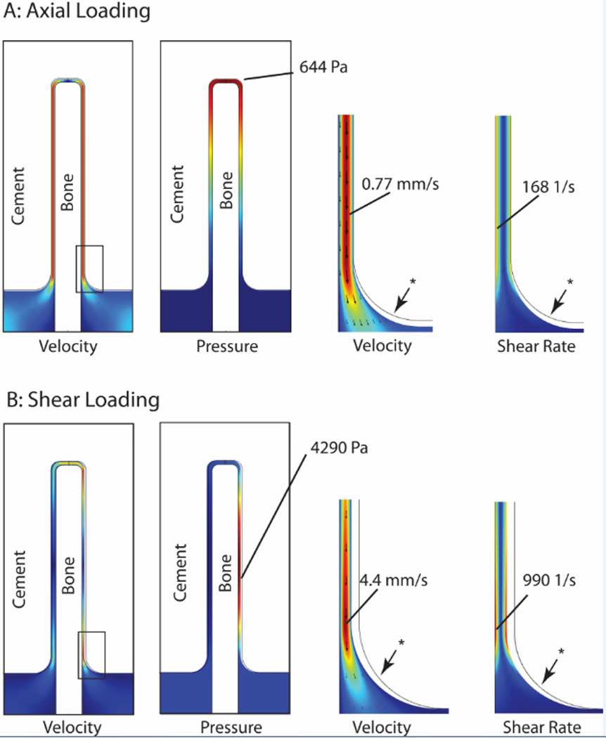
Fluid velocity, pressure, and shear rate at 0.25 s for axial (A) and shear loading (B) conditions with an 80% gap closing fraction, loading frequency of 1 Hz, and 0.1 Pa-s fluid viscosity. Red represents highest magnitudes, while dark blue represents 0 magnitude. * indicates undeformed position of fluid-cement interface.
The DOE regression analyses (Table 4) show that each of the five input parameters has a significant effect on at least one of the three outcome measures (shear stress, fluid velocity, pressure). Increasing viscosity results in higher shear stress and pressure. Increasing gap closing fraction resulted in an increasing in shear stress, pressure, and fluid velocity. Increasing loading frequency resulted in increase fluid velocity. Fluid shear stress, velocity, and pressure were always highest when the closing fraction was large (0.8), and the loading frequency was high (4 Hz) (Table 5).
Table 4.
Design of experiments (DOE) analysis indicates significant relationships (p<0.05) between model parameters and outcome measures. (+/− indicate positive/negative effect on outcome measures.)
| Parameter | Levels | Shear Stress (Pa) |
Pressure (Pa) |
Fluid Velocity (m/s) |
|---|---|---|---|---|
| R2 | 0.54 | 0.63 | 0.74 | |
| Viscosity (Pa-s) | 0.001 – 0.1 | + | + | |
| Gap closing fraction (GCF) | 0.1 – 0.8 | + | + | + |
| Gap thickness (mm) | 0.005 – 0.03 | − | + | |
| Loading direction | Axial - shear | − | ||
| Loading frequency (Hz) | 1 – 4 | + | ||
| Viscosity * GCF | + | + | ||
| Viscosity * Gap | − | |||
| GCF * Gap | + | |||
| GCF * Load Direction | − | |||
| GCF * Frequency | + | |||
| Load Direction * Gap | − |
Table 5.
Parameters that result in the maximum fluid values of the three outcome measures.
| Shear Stress | Velocity | Pressure | |
|---|---|---|---|
| Magnitude | 926 Pa | 23.4 mm/s | 82000 Pa |
| Loading direction |
Shear | Shear | Axial |
| Gap closing fraction |
0.8 | 0.8 | 0.8 |
| Gap thickness (µm) |
5 | 30 | 5 |
| Load frequency (Hz) |
4 | 4 | 4 |
| Fluid Viscosity | Marrow (0.1 Pa-s) |
Water (0.001 Pa-s) |
Marrow (0.1 Pa-s) |
To verify that the first loading cycle was representative of the steady-state response, the effect of number of loading cycles was analyzed for the shear loading case (30 µm gap, 0.8 GCF) through continuous loading for 10 cycles and assessing differences in shear rate response at 1 and 10 cycles. For the two peaks in shear rate, errors were very small (0.24% for peak 1 and 1.32% for peak 2).
A mesh sensitivity study was conducted with numbers of degrees of freedom (DOF) ranging from 7300 to 62000 for the model shown in Figure 3 with a 30 µm gap. Peak bone stress and fluid shear rate were used as the primary outcome metrics. The extremely fine mesh with 62000 DOF was used as the ‘exact’ answer to which other results were compared. With 9300 DOF, bone stress and fluid shear rate ‘errors’ were 7.9% and 6.3%, respectively. These reduced to 0.4% and 0.6% with 21000 DOF. Further refinement to 36000 DOF resulted in errors of 0.7% and 0.07%. These results show that models with ~20,000 DOF were sufficient to capture the peak stress and flow rate measures.
The effect of fixing the top of the trabecula to the cement, such as is used in Section 2.4, was assessed for a shear loading model with a 30 µm gap. The fixed case (Figure 6 D–F) resulted in reduced fluid shear rates, but substantially increased bone and cement stresses. Note that the bone and cement stress response mirrored the applied displacements, while the fluid flow had two peaks for each loading cycle due to egress and inflow.
3.3 Fluid Shear Rate for Retrieved Hip Replacements
In the fluid-structure study of experimental retrieved cement-bone interfaces from hip replacements, gap thicknesses ranged from 68 µm to 570 µm. Shear (2 to 664 µm) and normal (0.8 to 160 µm) micro-motions spanned a broad range [11]. For the 11 constructs, the peak fluid shear rate (Table 2) at the bone surface from gait loading was 39.5/s (24 SD) with a range of 5.1 to 79 1/s. From this analysis, a ‘homeostatic’ shear rate of 50 1/s was chosen to represent conditions below which bone resorption would not be anticipated.
3.4 Simulating Resorption
For the trabeculae-cement models developed (Section 2.4), at ‘time zero’, representing the immediate post-op condition, there were very high shear rates along much of the trabecular bone surface (Figure 7A). Peak shear rates occurred at 0.25 s of the 1 second loading cycle. Implementing bone loss via the resorption algorithm, there was a dramatic drop in fluid shear rate and nominal increase in bone stress and displacement of the cement relative to the bone (Figure 8) within the first few simulated ‘months’. Bone resorption continued in focal regions until 18 ‘months’ when erosion of the bone was nearly complete in two locations. The late increased displacement of the bone, resulted in much higher fluid shear rates, which in turn increased the rate of bone loss and higher trabecular bone stress (Figure 7B).
Figure 7.
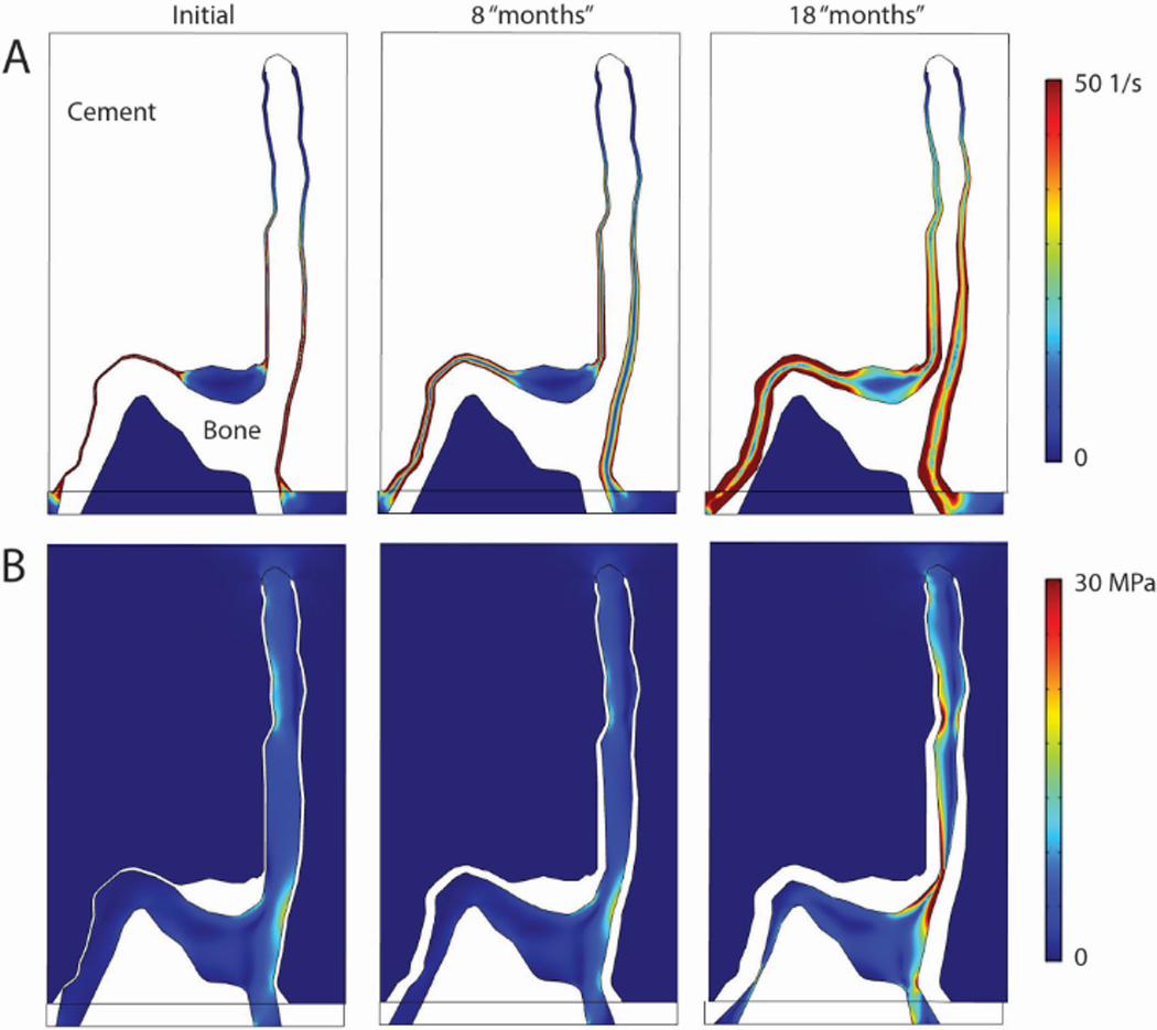
Fluid shear rate (A) and Von mises stress in bone and cement for initial gap condition, and after simulated bone resorption of 8 and 18 months.
Figure 8.
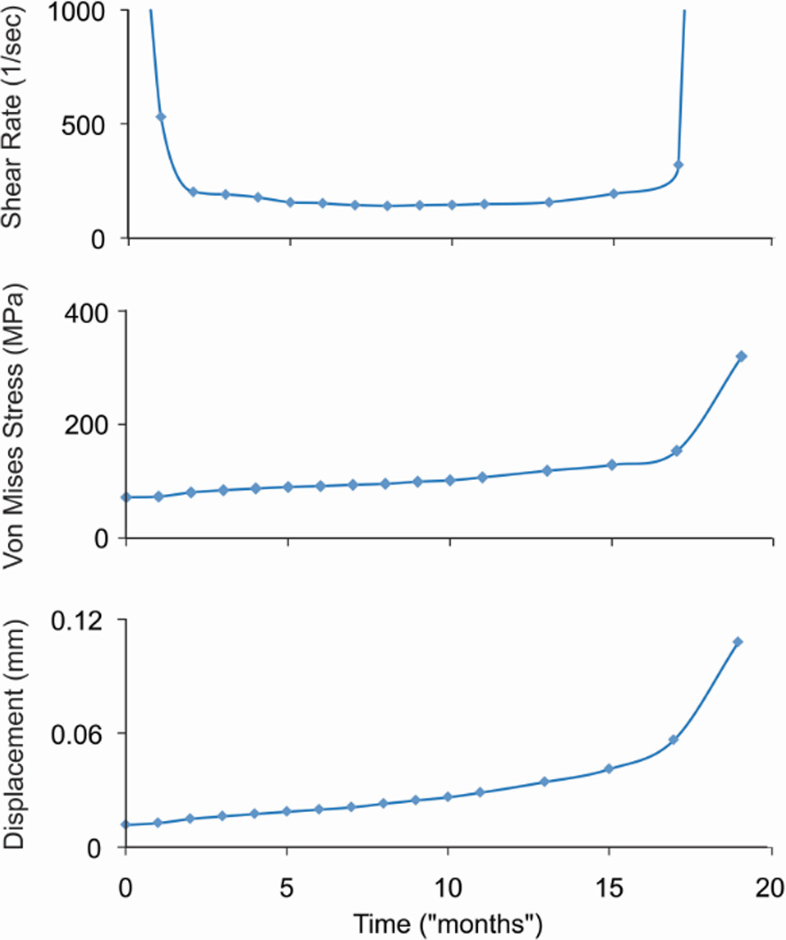
Maximum shear rate at the bone surface, von Mises stress in the trabecula, and displacement of the cement relative to the trabecula are shown as a function of time.
4. Discussion
The results of this study show that there are very small gaps at the interface between cement and trabecular bone in the immediate post-operative state (using laboratory prepared specimens as an analogue). When loaded, there are small, but measureable micro-motions between the trabeculae and cement. The small gaps between the trabecular surface and cement in the immediate post-operative state, combined with the induced micro-motions from loading of the joint, produce fluid flow conditions that appear to be supra-physiologic.
Several studies have explored fluid flow on bone or bone cells at physiological levels. Peak fluid shear stress at the trabecular surface surrounded by marrow for mechanically loaded vertebral trabecular bone at physiologic levels, has been estimated to be on the order of 1–5 Pa [14]. Low-magnitude/high-frequency vibration known for its anabolic effect on bone, results in fluid shear stresses in trabecular bone marrow of between 0.5 and 5.0 Pa [21]. Cell co-cultures subjected to oscillatory fluid flow (1 Pa shear stress) result in conditions of decreased osteoclastogenesis [22]. Osteocytes subjected to pulsatile fluid flow (0.7 Pa shear stress) produced conditioned medium that also inhibited osteoclast formation [23]. The calculated ‘homeo-static’ fluid shear stresses along the bone surface of retrieved cemented hip replacements (Section 2.3) in the present study would be in the range of 1.0 Pa to 7.9 Pa (for marrow). The shear stress magnitudes are similar to those cited above, suggesting that fluid shear stresses in this range may conducive to bone formation or normal turnover.
In contrast, the results of the idealized trabeculae-cement models suggest that loading can produce fluid shear stress and pressures that are several orders of magnitude larger than what would be considered physiologic. Fahlgren and coworkers [24] has shown that cortical surface pressures of ~53000 Pa and estimated flow velocities of 20 mm/s can cause extensive bone resorption using a rat model. McEvoy [25] showed that cultured macrophages, subjected to pressures of 35000 Pa increased cytokine production and bone resorption. High capsular pressure and implant motion were found to generate high flow rates (14 mm/s), using a computational fluid dynamic simulation to explore osteolysis along the proximal-lateral edge of total hip replacements [26]. Magnetic resonance imaging (MRI) has been used to measure the flow [27] around a canine bone implant with provision for micro-motion resulting in development of a sclerotic rim of bone with a gap between the implant and bone [28, 29]. Fluid velocity magnitudes of up to 14 mm/s were measured for these conditions. There are other examples of fluid induced bone lysis in the literature; subchondral bone cyst growth has been associated with fluid pressurization [30] and osteolysis due to pumping fluid through holes of cementless acetabular components has been associated with high fluid pressure and flow [31].
The flow and pressure magnitudes described above are in the same range as the maximum values found in this study (see Table 5), suggesting that the high fluid shear rates/stresses are a plausible mechanism to initiate and evolve localized loss of trabecular bone that interlocks with PMMA cement in joint replacements. The pattern of bone loss, with the majority at the base of the trabecula in the Section 2.4 simulation, is similar to that seen in some postmortem retrievals. Once the interface structure becomes unstable, it is likely that the trabecula fails or buckles. Note that bone material failure was not simulated here. This local loss of support could contribute to the progressive migration of the component for cases where the implants loosen [32]. It should also be noted that other resorption patterns are found in retrievals, some with complete loss of interlock between cement and bone.
While this work suggests that local fluid flow could be responsible for local trabecular resorption, it is also possible or even probable that other mechanisms such as stress shielding [33], monomer toxicity [34], heat or surgical necrosis [35, 36] also contribute to loss of bone. In addition, it is likely that individual trabeculae may be appositional with cement and well supported in some locations while having gaps in other locations [9]. More complex experiments and models of the micro and macro structure would be useful to explore these issues.
This project has several limitations. In this work, the experiments to determine interface gaps and micromotion were taken from one donor bone. Different interlock conditions and trabecular morphologies may result in different interface responses. However, for the purposes of this work, documenting that gaps can be small and that there is micromotion between the trabeculae and cement is sufficient to develop the concept of micromotion induced fluid flow. The finite element meshes were simple compared to a full 3D structure, but they do represent the typical features found in the interlock regions. In addition, they capture the complex fluid-structure interactions of the trabecula-cement interface; which has not, to the authors knowledge, been attempted previously.
The resorption algorithm was phenomenological by necessity because the osteoclast or osteoblast cellular response to very high shear rates/stresses has not been explored. However, we did incorporate a new shear rate limit into the constitutive model and this was based on computational fluid dynamics of 11 postmortem retrieved hip replacements. Specimens with very small and large interface gaps were included with corresponding small and large micro-motions (200 fold range), but the fluid shear rates at the bone surface spanned a much smaller range (10 fold range). This suggests that some level of fluid shear rate homeostatis may exist at the bone surface adjacent to the cement. Another limitation was that the exact nature of the fluid in the very thin cement-bone gaps is not known in terms of constituents or viscosity. For the final simulation with bone resorption, we assumed saline was the fluid in the gap. There is not definitive proof that the high fluid stresses cause increased osteoclastic resorption, but there are several laboratory studies that support this concept [13, 24, 25].
The bone resorption simulation used load control and resulted in high fluid shear rates early (with very thin gaps) and late (with large gaps, but increased motion). If the simulation were performed in displacement control, there would be early resorption due to the very thin gap, but this would diminish with time because the shear rate would decrease as the interface gap widened. As a complete total knee replacement construct, there may be some regions that experience constant or increasing loads with resorption, and others that may experience reduced loading or displacement. In the case presented here, after the early high resorption rate, resorption progressed at a near linear rate with time, followed by a period where there was a combination of increased fluid shear rate coupled to increased construct displacement. Studies of the fluid flow conditions for the trabeculae/cement interface following in-vivo service (as opposed to immediate post-op condition as was simulated here) could help determine conditions that result in long term interlock without excessive resorption.
Maintaining fixation of interfaces in joint replacements is critical for short and long-term clinical function. This work explores ‘unnaturally high’ fluid flow as a mechanism that may cause trabecular resorption found after in vivo service in regions where bone micro-interlocks with cement. In summary, we found that there are thin interface gaps between trabeculae and bone in the interlock regions of cemented knee replacements and these move when loaded. Very thin gaps, with large closing fractions, and high loading rates were associated with high fluid velocity, pressures, and shear stresses. The ‘supra-physiologic’ magnitude of these stresses was consistent with the literature for instances where osteolysis would be expected. The ‘homeostatic’ shear rate level for postmortem retrievals of hip replacements was much lower than the trabeculae-cement interlock regions and were of a magnitude consistent with conditions for bone maintenance. Applying a relatively simple resorption algorithm to the trabeculae-cement construct resulted in a resorption pattern that was similar to postmortem retrievals. Further, the resorption was progressive under load control conditions.
Acknowledgements
This work was funded by NIH AR42017.
References
- 1.Losina E, Thornhill TS, Rome BN, Wright J, Katz JN. The dramatic increase in total knee replacement utilization rates in the United States cannot be fully explained by growth in population size and the obesity epidemic. J Bone Joint Surg Am. 2012;94(3):201. doi: 10.2106/JBJS.J.01958. [DOI] [PMC free article] [PubMed] [Google Scholar]
- 2.Kurtz S, Ong K, Lau E, Mowat F, Halpern M. Projections of primary and revision hip and knee arthroplasty in the United States from 2005 to 2030. J Bone Joint Surg Am. 2007;89(4):780. doi: 10.2106/JBJS.F.00222. [DOI] [PubMed] [Google Scholar]
- 3.NIH Consensus State Sci Statements. 2003. NIH Consensus Statement on Total Knee Replacement; p. 1. [PubMed] [Google Scholar]
- 4.Kurtz SM, Ong KL, Schmier J, Mowat F, Saleh K, Dybvik E, Karrholm J, Garellick G, Havelin LI, Furnes O, Malchau H, Lau E. Future clinical and economic impact of revision total hip and knee arthroplasty. J Bone Joint Surg Am. 2007;89(Suppl 3):144. doi: 10.2106/JBJS.G.00587. [DOI] [PubMed] [Google Scholar]
- 5.Furnes O, Espehaug B, Lie S, Engesaeter L, Vollset S, Havelin L. American Academy of Orthopaedic Surgeons. Washington, DC: 2005. Prospective studies of hip and knee prostheses: The Norwegian Arthroplasty Register 1987-2004; p. SE024. [Google Scholar]
- 6.Adelaide, SA: www.aoa.org.au. 2009. Australian Orthopaedic Association National Joint Replacement Registry. [Google Scholar]
- 7.Kurtz SM, Lau E, Ong K, Zhao K, Kelly M, Bozic KJ. Future young patient demand for primary and revision joint replacement: national projections from 2010 to 2030. Clin Orthop Relat Res. 2009;467(10):2606. doi: 10.1007/s11999-009-0834-6. [DOI] [PMC free article] [PubMed] [Google Scholar]
- 8.Kurtz S, Mowat F, Ong K, Chan N, Lau E, Halpern M. Prevalence of primary and revision total hip and knee arthroplasty in the United States from 1990 through 2002. J Bone Joint Surg Am. 2005;87(7):1487. doi: 10.2106/JBJS.D.02441. [DOI] [PubMed] [Google Scholar]
- 9.Mann KA, Miller MA, Pray CL, Verdonschot N, Janssen D. A new approach to quantify trabecular resorption adjacent to cemented knee arthroplasty. J Biomech. 2012;45(4):711. doi: 10.1016/j.jbiomech.2011.12.008. [DOI] [PMC free article] [PubMed] [Google Scholar]
- 10.Gebert de Uhlenbrock A, Puschel V, Puschel K, Morlock MM, Bishop NE. Influence of time in-situ and implant type on fixation strength of cemented tibial trays - A post mortem retrieval analysis. Clin Biomech (Bristol, Avon) 2012 doi: 10.1016/j.clinbiomech.2012.06.008. [DOI] [PubMed] [Google Scholar]
- 11.Mann KA, Miller MA, Verdonschot N, Izant TH, Race A. Functional interface micromechanics of 11 en-bloc retrieved cemented femoral hip replacements. Acta Orthop. 2010;81(3):308. doi: 10.3109/17453674.2010.480938. [DOI] [PMC free article] [PubMed] [Google Scholar]
- 12.Miller MA, Hobbs A, Izant TH, Rimnac C, Mann KA. Annual Meeting of the Orthopaedic Research Society. New Orleans, LA: 2010. Functional micromechanics of enbloc retrieved tibial components; p. 2095. [Google Scholar]
- 13.van der Vis H, Aspenberg P, de Kleine R, Tigchelaar W, van Noorden CJ. Short periods of oscillating fluid pressure directed at a titanium-bone interface in rabbits lead to bone lysis. Acta Orthop Scand. 1998;69(1):5. doi: 10.3109/17453679809002345. [DOI] [PubMed] [Google Scholar]
- 14.Dickerson DA, Sander EA, Nauman EA. Modeling the mechanical consequences of vibratory loading in the vertebral body: microscale effects. Biomech Model Mechanobiol. 2008;7(3):191. doi: 10.1007/s10237-007-0085-y. [DOI] [PubMed] [Google Scholar]
- 15.COMSOL. COMSOL Multiphysics User's Guide. 2012. [Google Scholar]
- 16.Bathe KJ. Tine inf-sup condition and its evaluation for mixed finite element methods. Computers and Structures. 2001;79:243. [Google Scholar]
- 17.Donea J, Giuliani S, Halleux JP. An arbitrary lagrangian-eulerian finite element method for transient dynamic fluid-structure interactions. Computer Methods in Applied Mechanics and Engineering. 1982;33(1-3):689. [Google Scholar]
- 18.Chang PB, Williams BJ, Bhalla KS, Belknap TW, Santner TJ, Notz WI, Bartel DL. Design and analysis of robust total joint replacements: finite element model experiments with environmental variables. J Biomech Eng. 2001;123(3):239. doi: 10.1115/1.1372701. [DOI] [PubMed] [Google Scholar]
- 19.Mann KA, Miller MA, Khorasani M, Townsend KL, Allen MJ. The dog as a preclinical model to evaluate interface morphology and micro-motion in cemented total knee replacement. Vet Comp Orthop Traumatol. 2012;25(1):1. doi: 10.3415/VCOT-11-01-0014. [DOI] [PubMed] [Google Scholar]
- 20.Race A, Miller MA, Izant TH, Mann KA. Direct evidence of"damage accumulation" in cement mantles surrounding femoral hip stems retrieved at autopsy: Cement damage correlates with duration of use and BMI. J Biomech. 2011;44(13):2345. doi: 10.1016/j.jbiomech.2011.07.013. [DOI] [PMC free article] [PubMed] [Google Scholar]
- 21.Coughlin TR, Niebur GL. Fluid shear stress in trabecular bone marrow due to low-magnitude high-frequency vibration. J Biomech. 2012;45(13):2222. doi: 10.1016/j.jbiomech.2012.06.020. [DOI] [PubMed] [Google Scholar]
- 22.Kim CH, You L, Yellowley CE, Jacobs CR. Oscillatory fluid flow-induced shear stress decreases osteoclastogenesis through RANKL and OPG signaling. Bone. 2006;39(5):1043. doi: 10.1016/j.bone.2006.05.017. [DOI] [PubMed] [Google Scholar]
- 23.Tan SD, de Vries TJ, Kuijpers-Jagtman AM, Semeins CM, Everts V, Klein-Nulend J. Osteocytes subjected to fluid flow inhibit osteoclast formation and bone resorption. Bone. 2007;41(5):745. doi: 10.1016/j.bone.2007.07.019. [DOI] [PubMed] [Google Scholar]
- 24.Fahlgren A, Bostrom MP, Yang X, Johansson L, Edlund U, Agholme F, Aspenberg P. Fluid pressure and flow as a cause of bone resorption. Acta Orthop. 2010;81(4):508. doi: 10.3109/17453674.2010.504610. [DOI] [PMC free article] [PubMed] [Google Scholar]
- 25.McEvoy A, Jeyam M, Ferrier G, Evans CE, Andrew JG. Synergistic effect of particles and cyclic pressure on cytokine production in human monocyte/macrophages: proposed role in periprosthetic osteolysis. Bone. 2002;30(1):171. doi: 10.1016/s8756-3282(01)00658-5. [DOI] [PubMed] [Google Scholar]
- 26.Alidousti H, Taylor M, Bressloff NW. Do capsular pressure and implant motion interact to cause high pressure in the periprosthetic bone in total hip replacement? J Biomech Eng. 2011;133(12):121001. doi: 10.1115/1.4005455. [DOI] [PubMed] [Google Scholar]
- 27.Conroy MJ, Pedrono A, Bechtold JE, Soballe K, Ambard D, Swider P. High-resolution magnetic resonance flow imaging in a model of porous bone-implant interface. Magn Reson Imaging. 2006;24(5):657. doi: 10.1016/j.mri.2005.11.001. [DOI] [PubMed] [Google Scholar]
- 28.Bechtold JE, Mouzin O, Kidder L, Soballe K. A controlled experimental model of revision implants: Part II. Implementation with loaded titanium implants and bone graft. Acta Orthop Scand. 2001;72(6):650. doi: 10.1080/000164701317269102. [DOI] [PubMed] [Google Scholar]
- 29.Bechtold JE, Kubic V, Soballe K. A controlled experimental model of revision implants: Part I. Development. Acta Orthop Scand. 2001;72(6):642. doi: 10.1080/000164701317269094. [DOI] [PubMed] [Google Scholar]
- 30.Cox LG, Lagemaat MW, van Donkelaar CC, van Rietbergen B, Reilingh ML, Blankevoort L, van Dijk CN, Ito K. The role of pressurized fluid in subchondral bone cyst growth. Bone. 2011;49(4):762. doi: 10.1016/j.bone.2011.06.028. [DOI] [PubMed] [Google Scholar]
- 31.Walter WL, Clabeaux J, Wright TM, Walsh W, Walter WK, Sculco TP. Mechanisms for pumping fluid through cementless acetabular components with holes. J Arthroplasty. 2005;20(8):1042. doi: 10.1016/j.arth.2005.03.039. [DOI] [PubMed] [Google Scholar]
- 32.Ryd L, Albrektsson BE, Carlsson L, Dansgard F, Herberts P, Lindstrand A, Regner L, Toksvig-Larsen S. Roentgen stereophotogrammetric analysis as a predictor of mechanical loosening of knee prostheses. J Bone Joint Surg Br. 1995;77(3):377. [PubMed] [Google Scholar]
- 33.Chong DYR, Hansen UN, Venne R, Verdonschot N, Amis AA. The influence of tibial component fixation techniques on resorption of supporting bone stock after total knee replacement. J Biomech. 2011;44(5):948. doi: 10.1016/j.jbiomech.2010.11.026. [DOI] [PubMed] [Google Scholar]
- 34.Gough JE, Downes S. Osteoblast cell death on methacrylate polymers involves apoptosis. J Biomed Mater Res. 2001;57(4):497. doi: 10.1002/1097-4636(20011215)57:4<497::aid-jbm1195>3.0.co;2-u. [DOI] [PubMed] [Google Scholar]
- 35.Mjoberg B. Loosening of the cemented hip prosthesis. The importance of heat injury. Acta Orthop Scand Suppl. 1986;221:1. [PubMed] [Google Scholar]
- 36.Stanczyk M, van Rietbergen B. Thermal analysis of bone cement polymerisation at the cement-bone interface. J Biomech. 2004;37(12):1803. doi: 10.1016/j.jbiomech.2004.03.002. [DOI] [PubMed] [Google Scholar]