

Abstract
Proton radiotherapy represents a potential major advance in cancer therapy. Most current proton beams are spread out to cover the tumor using passive scattering and collimation, resulting in an extra whole-body high-energy neutron dose, primarily from proton interactions with the final collimator. There is considerable uncertainty as to the carcinogenic potential of low doses of high-energy neutrons, and thus we investigate whether this neutron dose can be significantly reduced without major modifications to passively scattered proton beam lines. Our goal is to optimize the design features of a patient-specific collimator or pre-collimator/collimator assembly. There are a number of often contradictory design features, in terms of geometry and material, involved in an optimal design. For example, plastic or hybrid plastic/metal collimators have a number of advantages. We quantify these design issues, and investigate the practical balances that can be achieved to significantly reduce the neutron dose without major alterations to the beamline design or function. Given that the majority of proton therapy treatments, at least for the next few years, will use passive scattering techniques, reducing the associated neutron-related risks by simple modifications of the collimator assembly design is a desirable goal.
1. Introduction
The development of hospital-based proton facilities potentially represents a major step forward in radiotherapy, in part because of excellent dose distributions around the tumor (Chang et al 2006), and in part because of the lower whole-body dose compared with photon radiotherapy (Miralbell et al 2002). However, the issue of whole-body exposure to secondary neutrons produced by the scattering components of passively scattered proton beams has recently attracted some attention (Binns and Hough 1997, Agosteo et al 1998, Schneider et al 2002, Yan et al 2002, Roy and Sandison 2004, Fontenot et al 2005, Jiang et al 2005, Polf and Newhauser 2005, Hall 2006, Mesoloras et al 2006, Tayama et al 2006, Hecksel et al 2007, Wroe et al 2007, Zheng et al 2007, Brenner and Hall 2008, Fontenot et al 2008, Moyers et al 2008, Taddei et al 2008, Yonai et al 2008, Zacharatou Jarlskog et al 2008, Zacharatou Jarlskog and Paganetti 2008, Newhauser et al 2009, Perez-Andujar et al 2009, Shin et al 2009).
The issue of secondary neutron exposure arises primarily because it is generally necessary to spread out the narrow pencil beam produced by a proton accelerator, in order to provide uniform coverage over the target. This can be done by using deflecting magnets to sweep the beam across the tumor (active scanning; Lomax et al 2004) or, as in most current proton radiotherapy facilities, by inserting scattering material into the beam (passive scattering; Koehler et al 1977). Because passive scattering necessarily requires a number of material components in the beamline, specifically scatterers and collimators, proton interactions with these components result in the production of high-energy secondary neutrons. In addition to proton interactions with beamline components, there will also be an unavoidable neutron dose from proton interactions within the patient.
In passively scattered clinical proton beams, the dominant source of patient neutron dose is generally the final collimator, which is located close to the patient (Jiang et al 2005, Mesoloras et al 2006, Zheng et al 2007, Zacharatou Jarlskog et al 2008, Perez-Andujar et al 2009). The proton beam is always larger than the patient-specific aperture, to a lesser or greater extent, so protons will bombard the collimator and produce secondary neutrons. This patient-specific collimator is commonly fabricated out of brass, with a patient-specific aperture manufactured to match the target; an alternate methodology here is to use a multi-leaf collimator instead of a patient-specific manufactured device (Kanai et al 1983, McDonough and Tinnel 2007, Yonai et al 2008).
Of course the actual neutron doses, and therefore any associated second-cancer risks, will depend on the particular beamline geometry as well as the patient geometry. In fact there have been a variety of different estimates of the risks associated with the secondary neutron exposure in proton radiotherapy, which differ both because different geometries were used, resulting in different neutron doses, but also because very different assumptions were made about the relative biological effectiveness for the carcinogenic potential of low doses of high-energy neutrons (Brenner and Hall 2008, Newhauser et al 2009). It is pertinent to note that, because the epidemiological basis for low-dose high-energy neutron risk estimates is not strong, the confidence intervals around the risk estimates are wide, with an estimated uncertainty of at least a factor of 4 (Brenner and Hall 2008). However, irrespective of the absolute value of the neutron-induced risks, we would expect that lowering the secondary neutron dose will lead to a corresponding reduction in the neutron-induced second-cancer risk—thus these neutron doses should always be as low as reasonably achievable.
The number of proton facilities worldwide is increasing rapidly (Olsen et al 2007, Smith 2009). Currently almost all of the 30 proton therapy machines that are in operation worldwide predominantly use passive scattering. In part, this is because proton beam scanning technology is still in its developmental stage and more suited to research-oriented facilities (Safai et al 2008, Smith 2009). Thus most proton treatments, worldwide, are likely to continue to use passive scattering technology, at least for the next decade or so (Newhauser et al 2009). In this light, and in light of the potentially significant carcinogenicity of low doses of high-energy neutrons (NCRP 1990, Little 1997, Heimers 1999, Nolte et al 2005, Kellerer et al 2006, Brenner and Hall 2008), it is important to minimize the patient dose produced by these secondary neutrons.
In that the main sources of neutron exposure in passively scattered proton radiotherapy are the patient-specific collimation devices, our goal here is to characterize the design features of an optimal patient-specific collimator or pre-collimator/collimator assembly. Specifically there are a number of often contradictory design features, in terms of geometry and material, involved in an optimal design. As an example, thicker collimators result in reduced neutron doses, but can adversely affect the lateral penumbra of the collimated beam. We quantify these design issues, and investigate what practical balances can be achieved to significantly reduce the neutron dose without significant alteration to the beamline design or function.
2. Methods
2.1. Approaches for reducing the whole-body dose produced by secondary neutrons
Prima facie, the most direct way to reduce the whole-body neutron dose in a passively scattered system is simply to add shielding between the beamline neutron sources and the patient, and this has been suggested (Taddei et al 2008). There are limitations to this approach: first, the bulk shielding would be extremely heavy, and thus particularly problematic for a rotating gantry system. Second, organs close to the treatment volume cannot be shielded in this way, as inserting shielding between the patient-specific collimator and the patient here would increase the collimator–patient distance, which would adversely affect the lateral penumbra of the collimated beam (Slopsema and Kooy 2006). Organs close to the treatment volumes are the ones subject to the highest neutron dose, because the secondary neutrons are emitted predominantly in the forward direction.
A conceptually similar approach is simply to make the patient-specific collimator thicker. As discussed below, this is an effective way of reducing the secondary neutron dose, because the downstream parts of the patient-specific collimator absorb neutrons produced in the upstream parts. For example, by doubling the thickness of the brass collimator, from 65 mm to 130 mm, the peak neutron dose can be approximately halved (see below). However increasing the collimator thickness will adversely affect the lateral penumbra (Slopsema and Kooy 2006), which limits the applicability of this approach. We quantify here a practical balance between increased patient-specific collimator thickness and degraded lateral penumbra.
An alternate/complementary approach which should not adversely affect the lateral penumbra is to insert a customized pre-collimator upstream of the patient-specific collimator, in order to limit the number of protons unnecessarily impinging on the patient-specific collimator. A two-stage approach to collimation is standard in electron beam therapy (Bagne 1974), and several proton facilities have used (Bonnett et al 1993, Moyers 1999, Tayama et al 2006, Zheng et al 2007, Yonai et al 2008) or proposed (Taddei et al 2008) this approach. Pre-collimators made out of brass, tungsten alloy, aluminum, and copper have been used or proposed, all with a thickness just sufficient to stop the proton beam. Generally, these pre-collimator/collimator assemblies have not been fully optimized to minimize the secondary neutron dose, which is our goal here. For example, when a pre-collimator is used for proton radiotherapy, the patient-specific collimator provides a second function – that of shielding secondary neutrons produced in the pre-collimator.
2.2. Simplified geometry to optimize collimator material/geometry
In order to elucidate the general characteristics of the collimator and pre-collimator, we have used a highly simplified geometry. Illustrated in figure 1, this is designed to compare collimator and pre-collimator generated neutron doses, for different materials and geometries. Modeled here is a patient-specific collimator, downstream of which is a cylindrical patient phantom, and upstream of which is cylindrical pre-collimator; the concept here is to have available a variety of cylindrical pre-collimators with different internal diameters. The pre-collimator with smallest internal diameter which does not `block' the patient-specific collimator aperture would be used for each patient. Our goal was to clarify the effects of the material, thickness and location of the pre-collimator/collimator system on the scattered neutron dose to the patient.
Figure 1.
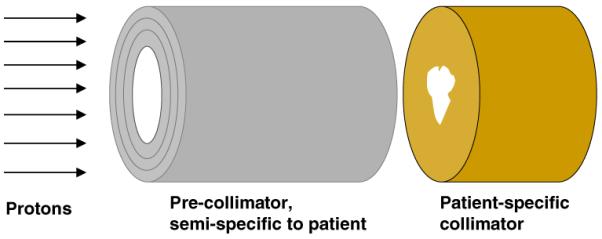
Geometry for the simplified Monte Carlo simulations. A uniform mono-energetic 235 MeV proton beam is incident on the face of the pre-collimator, which is upstream of the patient-specific collimator which is, in turn, immediately upstream of a cylindrical homogeneous tissue-equivalent phantom (to the right, not shown). The pre-collimator prevents unnecessary protons from impinging on the patient-specific collimator, while the final collimator provides the patient-specific collimation, but also shields the patient from neutrons produced in the pre-collimator. For these calculations, both the collimator and pre-collimator had circular internal and external diameters, respectively, of 50 and 113 mm. Doses due to neutrons originating in the collimator were tallied in 10 mm thick slices along the length of a cylindrical homogeneous tissue-equivalent phantom (1.5 m length × 0.5 m diameter), axis perpendicular to the proton-beam direction, located immediately downstream of the patient-specific collimator.
Studies were made for several different collimator/pre-collimator materials including brass, nickel, tungsten alloy, iron, cerrobend, and a high-density plastic; details of these materials are given in table 1. With the exception of plastic, all the materials considered have either been used or proposed for proton collimators. Plastic is a desirable collimator material from the perspective of its lower cross-section for neutron production (Meier et al 1992), machineability, light weight, and also because it is far less activated by high-energy protons compared to metals (Sisterson 2002). As quantified below, the disadvantage of plastic is its low density compared to metals, resulting in a thicker collimator being required to stop protons of a given energy. For the calculations shown here, a very high-density polyethylene was used (Shieldwerx 2007), density 1.65 g cm−3), for which a thickness of 195 mm is required to stop 235 MeV protons. As discussed below, some hybrid plastic/metal collimators have also been investigated.
Table 1.
Details of the candidate materials studied for collimators and pre-collimators
| Material | Composition by weight | Density (g cm−3) | Thickness to stop 235 MeV protons (mm) |
|---|---|---|---|
| Brass | 61.5% Cu; 35.2% Zn; 3.3% Pb | 8.5 | 65 |
| Tungsten alloy | 90% W; 6% Ni; 4% Cu | 16.9 | 40 |
| Cerrobend | 50% Bi; 26.7% Pb; 13.3% Sn; 10% Cd | 9.4 | 75 |
| Nickel | 100% Ni | 8.9 | 56 |
| Iron | 100% Fe | 7.9 | 63 |
| SWX-207HD polyethylene (Shieldwerx 2007) | 84.9% C; 14.2% H; 0.9% B | 1.65 | 195 |
2.3. Detailed geometry for lateral penumbra calculations
In order to assess the effects of collimator design changes on the lateral penumbra of the final proton beam, the gantry treatment nozzles and collimators from the Massachusetts General Hospital (MGH) beamline were modeled in detail. Figure 2 illustrates the geometries that were used to simulate realistic beam delivery scenarios. Beam and treatment-head settings were chosen to represent a typical field, with a prescribed range of 157 mm, a modulation width of 68.5 mm, and an aperture opening diameter of 60 mm. The area irradiated with protons at the base plate position corresponds to a diameter of roughly 250 mm, depending on the setting of variable collimators upstream of the snout retraction area. Thus, part of the proton beam is stopped at the variable collimators upstream of the snout retraction area, part at the base plate and the snout, and part in the patient-specific aperture.
Figure 2.
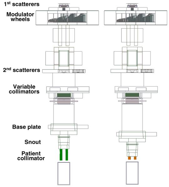
Simulations of the proton therapy treatment heads at the gantry beamlines at MGH, with a 65-mm thick brass collimator (above), and an optimized plastic or metal/plastic collimator (below). The proton beam is incident from the left, and the modulated collimated beam is incident on a water phantom on the right. Beam and treatment-head settings were chosen to represent a typical field, with a prescribed range of 157 mm, a modulation width of 68.5 mm, and an aperture opening diameter of 60 mm. The area irradiated with protons at the base plate position corresponds to a diameter of roughly 250 mm, depending on the setting of variable collimators upstream of the snout retraction area. The treatment head components are described in detail elsewhere (Paganetti et al 2004).
2.4. Monte Carlo simulation techniques
For the calculations using the simplified geometry in figure 1, we used the MCNPX (version 2.6d) Monte Carlo transport code (Hendricks et al 2003) to model the transport of a uniform flux of monoenergetic 235 MeV protons, normally incident on the precollimator and/or patient-specific collimator. The resulting neutron dose was tallied in a simplified homogeneous tissue phantom immediately downstream of the patient-specific collimator (see figure 1 caption). MCNPX is designed to simulate the transport of protons and neutrons (and many other radiations) at high and low energies, and has been extensively used and validated to model proton radiotherapy beamlines. For energies up to 150 MeV, evaluated nuclear interaction cross-section libraries were used where available (Chadwick et al 2006); above this energy, and for elements where evaluated cross-section libraries are not available, cross-sections were estimated within the MCNPX code using nuclear-reaction model calculations (Hendricks et al 2003). Collimator-produced neutron doses were estimated using an F6 MCNPX tally (Hendricks et al 2003), in 10 mm wide slices along the cylindrical tissue phantom axis.
For studies of the lateral penumbra of the final proton beam (figure 2), the gantry treatment nozzle from the Massachusetts General Hospital beamline was modeled in detail (Paganetti et al 2008), including the various collimators under study. Here, the Geant4 (version 4.8.0) Monte Carlo transport code (Allison 2007) was used, which has been extensively utilized for proton therapy beamline design and characterization (van Luijk et al 2001, Paganetti et al 2004). For comparison with neutron dose estimates from other treatment heads (e.g., Gottschalk 2006, Hall 2006, Paganetti 2007), the calculated on-axis dose for the geometry shown in figure 2, from neutrons originating in a 65-mm brass collimator, was 0.42 mGy/treatment Gy (in the center of the beam in a 0.5 m diameter cylindrical water phantom oriented perpendicular to the beam axis).
3. Results
3.1. Optimizing the patient-specific collimator
3.1.1. Effect of patient-specific collimator material
The results in figure 3 illustrate the significance of the patient-specific collimator material. Each collimator was just sufficiently thick to stop 235 MeV protons (see table 1), and for these studies no pre-collimation was used.
Figure 3.
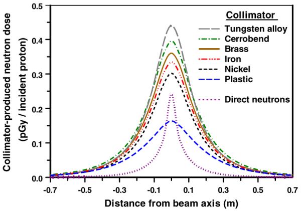
Calculated patient dose (per proton incident on the face of the collimator) from neutrons originating in patient-specific collimators made out of different materials. Geometry was as in figure 1, with no pre-collimator. The doses were tallied in a cylindrical tissue-equivalent phantom, axis perpendicular to the beam axis, located immediately downstream of the collimator, as a function of distance from the proton beam axis. Typical statistical uncertainties (1σ) in the results related to the Monte Carlo simulation are ±0.3% on axis, and ±1% at 0.7 m off axis. The thicknesses of each of the collimators correspond to the range of 235 MeV protons in that collimator material (see table 1). Also shown is the `direct' neutron dose arising from proton interactions in the tissue phantom itself.
It can be seen in figure 3 that, purely from the perspective of the secondary neutron dose, plastic is the preferred material for the patient-specific collimator. This is in part because plastic has a much lower cross-section for proton-induced neutron production, but also because the plastic collimator is physically much longer than the metal collimators. As discussed in the next section, the extra length of the plastic collimator may be problematic due to its effect on the lateral penumbra of the final beam.
Considering the thinner metallic collimators, again from the perspective of secondary neutrons, nickel is the preferred material for the patient-specific collimator (figure 3). However, from the perspective of the convenience and cost of machining patient-specific collimators, brass is a more practical material, and the subsequent simulations regarding the pre-collimator were therefore performed based on a 65 mm thick brass patient-specific collimator. Should a multi-leaf design be used for the patient-specific collimator, from the perspective of the secondary neutron dose, it might usefully have nickel leaves (Bues et al 2005).
Another option here would be a hybrid plastic/brass collimator. Table 2 shows the peak neutron doses for various thicknesses of plastic and brass, in each case the total thickness being just sufficient to stop 235 MeV protons.
Table 2.
Peak neutron doses for hybrid brass/plastic collimators with overall thickness sufficient to stop 235 MeV protons. The geometry used here (figure 1, no pre-collimator) is identical to those for the calculations shown in figure 3. Typical statistical uncertainties (1σ) in the results, related to the Monte-Carlo simulation, are ±0.3%.
| Brass thickness (mm) | Plastic thickness (mm) | Total collimator thickness (mm) | Collimator-related peak neutron dose (pGy/incident proton) |
|---|---|---|---|
| 65 | 0 | 65 | 0.36 |
| 55 | 25 | 80 | 0.29 |
| 50 | 41 | 91 | 0.25 |
| 45 | 59 | 104 | 0.22 |
| 40 | 75 | 115 | 0.20 |
| 35 | 94 | 129 | 0.18 |
| 25 | 128 | 153 | 0.17 |
| 0 | 195 | 195 | 0.16 |
3.1.2. Effect of patient-specific collimator thickness
Figure 4 shows the effect on the collimator-induced neutron dose of using thicker collimators; use of a thicker collimator significantly reduces the neutron dose, because the downstream part of the collimator acts as a shield for neutrons produced in the upstream part.
Figure 4.
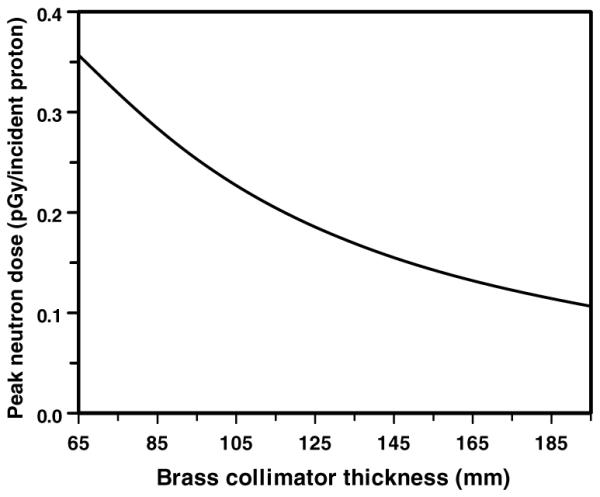
Calculated peak patient dose (per proton incident on the face of the collimator) from neutrons originating in a brass collimator of various thicknesses. Geometry as in figures 1 and 3 with no pre-collimator. Note the minimum brass collimator thickness (i.e., to stop 235 MeV protons) is 65 mm.
As discussed above, such thicker collimators would be expected to impact the lateral penumbra of the beam, and this was quantified using the realistic beamline geometry illustrated in figure 2. Specifically, figure 5 shows the effect of a thicker collimator (200 mm versus 65 mm) on the final beam lateral penumbra. As expected (Slopsema and Kooy 2006), the thicker collimator does adversely affect the lateral penumbra, primarily in the entrance region, but also, to a lesser extent, in the spread out Bragg peak.
Figure 5.
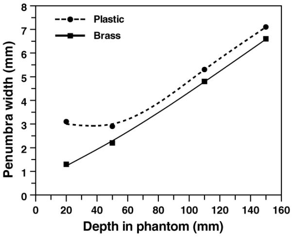
Calculated lateral penumbra widths (beam width at 80% of maximum dose minus beam width at 20% of maximum dose) for a 65 mm thick brass and a 200 mm SWX-207HD polyethylene collimator (aperture opening diameter 60 mm), using the detailed beamline geometry shown in figure 2, and typical beam and nozzle settings. In the entrance region, the lateral penumbra is worse from the thicker plastic collimator, but in the spread-out Bragg peak (in this case, from 110 to 150 mm), the difference in the lateral penumbra is 0.5 mm.
3.2. Optimizing a pre-collimator
3.2.1. Effect of pre-collimator material
All the pre-collimator calculations shown were made in conjunction with a downstream 65 mm thick brass collimator. Figure 6 shows the significance of the pre-collimator material, specifically nickel, brass, tungsten, and the high-density polyethylene described above. The results in figure 6 are for pre-collimator thicknesses that are just sufficient to stop 235 MeV protons, with the pre-collimator immediately upstream of the patient-specific collimator (the effects of different thicknesses for the pre-collimator, and of the location of the pre-collimator, are each discussed below).
Figure 6.
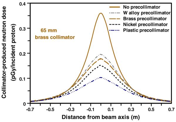
Calculated patient dose (per proton incident on the face of the collimator) from neutrons originating in a pre-collimator + collimator configuration (see figure 1). In each case the patient-specific collimator was 65-mm thick brass; the four pre-collimators were each of sufficient thickness to stop 235 MeV protons (see table 1), and were located immediately upstream of the patient-specific collimator.
As expected, pre-collimators significantly reduce the secondary neutron dose, by reducing the number of protons incident on the patient-specific collimator, and with the patient-specific collimator acting as a neutron shield for neutrons generated in the pre-collimator. Thus, for example, the nickel and plastic pre-collimators reduce the peak secondary neutron dose, respectively, by factors of 2.2 and 3.6.
3.2.2. Effect of pre-collimator mass and thickness
The results shown in figure 6 are for pre-collimator thicknesses just sufficient to stop 235 MeV protons; thus each pre-collimator, made from a different material, had a different thickness and mass. The masses of the four pre-collimators modeled in figure 6 were 2.6 kg (plastic), 4.0 kg (Ni), 4.5 kg (brass) and 5.5 kg (tungsten alloy). As a function of mass, therefore, the plastic pre-collimator is clearly the most efficient.
Figure 7 shows the effect of changing the pre-collimator thickness, again for precollimators located immediately upstream of the patient-specific collimator (the effects of the location of the pre-collimator are discussed below). For a given thickness, nickel and tungsten are equally effective as pre-collimators (though for a given thickness, nickel is considerably lighter), with brass and plastic somewhat less effective per unit thickness. It may also be noted that there is monotonic increase in the effectiveness of the pre-collimator with increased thickness, both for thicknesses less than, and for thicknesses more than, is required to stop the primary protons.
Figure 7.
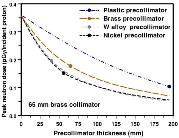
Calculated peak patient dose (per proton incident on the face of the collimator) from neutrons originating in a pre-collimator + collimator configuration (see figure 1), as a function of the thickness of the pre-collimator. In each case the patient-specific collimator was 65 mm thick brass, and the pre-collimator was located immediately upstream of the patient-specific collimator. The points correspond to the pre-collimator thickness sufficient to stop 235 MeV protons (as in figure 6).
3.2.3. Effect of pre-collimator location
In principle, the pre-collimator can be located at almost any location upstream of the patient-specific collimator. Figure 8 shows the lateral distribution of neutron dose in the phantom for pre-collimator/collimator separations of 0, 0.5 and 1.0 m. As expected, on axis, the larger the separation, the smaller the dose, simply because the neutrons produced in the pre-collimator originate further from the patient. On the other hand, as the pre-collimator/collimator separation increases, the patient-specific collimator no longer acts as a neutron shield with respect to patient locations well off axis, so the off-axis neutron dose increases.
Figure 8.
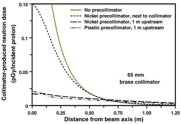
Calculated patient dose (per proton incident on the face of the collimator) from neutrons originating in a pre-collimator + brass collimator configuration (see figure 1), for different pre-collimator/collimator separations. In each case the collimator was 65 mm thick brass. The pre-collimator thicknesses were as in table 1 and figure 6.
3.3. Proton activation of plastic versus metals
A new consideration in the current work is the potential use of high-density plastic for pre-collimation or collimation. Apart from their lower neutron production cross-sections, a key advantage of a polyethylene pre-collimator or collimator is that it would be significantly less radioactive after use, compared with metallic devices. In plastics, the only relevant proton-activated isotope with a half life more than a few minutes is 7Be, which has production cross-sections in plastics of less than 10 mb at all proton energies of relevance here (Rayudu 1964). In contrast, proton interactions with metallic materials such as brass produce a far greater number of activated isotopes, such as 58Co, 57Co, 56Co, 51Cr, 54Mn and 65Zn, all with higher production cross-sections than proton-induced 7Be in plastic, as confirmed by experimental activity measurements (Fassbender et al 1997, Sisterson 2002).
To quantify the relative activation rates for polyethylene versus brass, we used the standard formula for induced activity in a thick target (Krasnov et al 1977), together with activation cross-sections from the MENDL-2P database augmented by LAHET calculations (Titarenko et al 2005), and stopping powers from SRIM (Ziegler et al 2002). The total activity of induced radioisotopes with half lives more than 1 h after a short 200 MeV proton irradiation was 14 times lower in the high-density polyethylene collimator compared with a brass collimator. High-density polyethylene collimators/pre-collimators would thus be handleable or discardable shortly after use.
4. Conclusions
We show here that an optimized pre-collimator/collimator system can significantly reduce the secondary patient dose produced by neutrons which originate in the passive-scattering beamline components, without major alterations to the beamline design or function.
Considering first the patient-specific collimator, because of its lower cross-section for proton-induced neutron production, the optimal material is high-density polyethylene, which has advantages in terms of lightness, machinability, cost and, importantly, reduced sensitivity to activation. Its disadvantage lies in the required collimator thickness (195 mm for 235 MeV protons). More generally, increased thickness of any collimator will reduce the neutron dose, at the cost of a potentially degraded lateral penumbra of the final beam. Based on our calculations, a 100 mm thick collimator is unlikely to have any significant adverse impact on the lateral penumbra, and this could be achieved with a hybrid plastic-metal collimator, which would have the advantage of reduced activation, or with a purely metallic collimator. With regard to the choice of metal, if the patient-specific collimators are individually machined, brass remains an appropriate choice; if a multi-leaf collimator (MLC) is used, then nickel may be the optimal material (Bues et al 2005).
Considering now pre-collimators, these have the advantage of lowering the neutron dose while still allowing the use of thin patient-specific collimators, i.e., there would be no impact on the lateral penumbra of the collimated beam. One can envisage simply using exchangeable semi-patient-specific cylinders (or cylindrical inserts), using the smallest aperture diameter which will not block the patient-specific aperture in the final collimator, or as an MLC. In either case, nickel appears the optimal material for the pre-collimator. From the perspective of the thickness of the pre-collimator, the results suggest `the thicker the better', and so the thickness would be determined by issues such as weight and convenience. With regard to the location of the pre-collimator, there are advantages and disadvantages to different upstream locations, and one might envisage this choice being highly beamline specific. A far upstream location results in less neutron dose on axis, but somewhat more neutron dose significantly off axis. Of course, there are other considerations as to the location of the pre-collimator – ideally it should be downstream of the scattering foils, for example.
In conclusion, we do not know with any certainty the cancer risks associated with secondary neutrons originating in the patient collimator, in large part because there are major uncertainties about the relative biological effectiveness of low doses of high-energy neutrons. Given that the majority of proton therapy treatments, at least for the next few years, will be with passive scattering techniques, reducing the associated neutron-related second-cancer risks by a simple modification of the collimator assembly design is a desirable and practical goal.
Acknowledgments
This work was supported in part by NIH grants P41-EB002033, PO1-CA49062 and R01-CA088074, and DOE grants DE-FG02-03ER63441 and DE-FG02-03ER63629.
References
- Agosteo S, Birattari C, Caravaggio M, Silari M, Tosi G. Secondary neutron and photon dose in proton therapy. Radiother. Oncol. 1998;48:293–3053. doi: 10.1016/s0167-8140(98)00049-8. [DOI] [PubMed] [Google Scholar]
- Allison J. Facilities and methods: Geant4—a simulation toolkit. Nucl. Phys. News. 2007;17:20–4. [Google Scholar]
- Bagne F. Effects of collimator scattering on dose for a 45 MeV betatron. Phys. Med. Biol. 1974;19:236. [Google Scholar]
- Binns PJ, Hough JH. Secondary dose exposures during 200 MeV proton therapy. Radiat. Prot. Dosim. 1997;70:441–4. [Google Scholar]
- Bonnett DE, Kacperek A, Sheen MA, Goodall R, Saxton TE. The 62 MeV proton beam for the treatment of ocular melanoma at Clatterbridge. Br. J. Radiol. 1993;66:907–14. doi: 10.1259/0007-1285-66-790-907. [DOI] [PubMed] [Google Scholar]
- Brenner DJ, Hall EJ. Secondary neutrons in clinical proton radiotherapy: a charged issue. Radiother. Oncol. 2008;86:165–70. doi: 10.1016/j.radonc.2007.12.003. [DOI] [PubMed] [Google Scholar]
- Bues M, Newhauser WD, Titt U, Smith AR. Therapeutic step and shoot proton beam spot-scanning with a multi-leaf collimator: a Monte Carlo study. Radiat. Prot. Dosim. 2005;115:164–9. doi: 10.1093/rpd/nci259. [DOI] [PubMed] [Google Scholar]
- Chadwick MB, et al. ENDF/B-VII.0: next generation evaluated nuclear data library for nuclear science and technology. Nucl. Data Sheets. 2006;107:2931–3059. [Google Scholar]
- Chang JY, Zhang X, Wang X, Kang Y, Riley B, Bilton S, Mohan R, Komaki R, Cox JD. Significant reduction of normal tissue dose by proton radiotherapy compared with three-dimensional conformal or intensity-modulated radiation therapy in Stage I or Stage III non-small-cell lung cancer. Int. J. Radiat. Oncol. Biol. Phys. 2006;65:1087–96. doi: 10.1016/j.ijrobp.2006.01.052. [DOI] [PubMed] [Google Scholar]
- Fassbender M, Shubin YN, Lunev VP, Qaim SM. Experimental studies and nuclear model calculations on the formation of radioactive products in interactions of medium energy protons with copper, zinc and brass: estimation of collimator activation in proton therapy facilities. Appl. Radiat. Isot. 1997;9:1221–30. [Google Scholar]
- Fontenot J, Taddei P, Zheng Y, Mirkovic D, Jordan T, Newhauser W. Equivalent dose and effective dose from stray radiation during passively scattered proton radiotherapy for prostate cancer. Phys. Med. Biol. 2008;53:1677–88. doi: 10.1088/0031-9155/53/6/012. [DOI] [PubMed] [Google Scholar]
- Fontenot JD, Newhauser WD, Titt U. Design tools for proton therapy nozzles based on the double-scattering foil technique. Radiat. Prot. Dosim. 2005;116:211–5. doi: 10.1093/rpd/nci229. [DOI] [PubMed] [Google Scholar]
- Gottschalk B. Neutron dose in scattered and scanned proton beams: in regard to Eric J Hall (Int. J. Radiat. Oncol. Biol. Phys. 2006 65 1–7) Int. J. Radiat. Oncol. Biol. Phys. 2006;66:1594. doi: 10.1016/j.ijrobp.2006.08.014. [DOI] [PubMed] [Google Scholar]
- Hall EJ. Intensity-modulated radiation therapy, protons, and the risk of second cancers. Int. J. Radiat. Oncol. Biol. Phys. 2006;65:1–7. doi: 10.1016/j.ijrobp.2006.01.027. [DOI] [PubMed] [Google Scholar]
- Hecksel D, Sandison GA, Farr JB, Edwards AC. Scattered neutron dose equivalent from an active scanning proton beam delivery system. Australas. Phys. Eng. Sci. Med. 2007;30:326–30. [PubMed] [Google Scholar]
- Heimers A. Cytogenetic analysis in human lymphocytes after exposure to simulated cosmic radiation which reflects the inflight radiation environment. Int. J. Radiat. Biol. 1999;75:691–8. doi: 10.1080/095530099140023. [DOI] [PubMed] [Google Scholar]
- Hendricks JS, et al. MCNPX version 2.5.c LANL Report LA-UR-03-2202. Los Alamos National Laboratory; Los Alamos, NM: 2003. [Google Scholar]
- Jiang H, Wang B, Xu XG, Suit HD, Paganetti H. Simulation of organ-specific patient effective dose due to secondary neutrons in proton radiation treatment. Phys. Med. Biol. 2005;50:4337–53. doi: 10.1088/0031-9155/50/18/007. [DOI] [PubMed] [Google Scholar]
- Kanai T, Kawachi K, Matsuzawa H, Inada T. Broad beam three-dimensional irradiation for proton radiotherapy. Med. Phys. 1983;10:344–6. doi: 10.1118/1.595254. [DOI] [PubMed] [Google Scholar]
- Kellerer AM, Ruhm W, Walsh L. Indications of the neutron effect contribution in the solid cancer data of the A-bomb survivors. Health Phys. 2006;90:554–64. doi: 10.1097/01.HP.0000184917.94232.cd. [DOI] [PubMed] [Google Scholar]
- Koehler AM, Schneider RJ, Sisterson JM. Flattening of proton dose distributions for large-field radiotherapy. Med. Phys. 1977;4:297–301. doi: 10.1118/1.594317. [DOI] [PubMed] [Google Scholar]
- Krasnov NN, Zatolokin BV, Konstantinov IO. Some problems of calibration technique in charged particle activation analysis. J. Radioanal. Chem. 1977;39:171–7. [Google Scholar]
- Little MP. Estimates of neutron relative biological effectiveness derived from the Japanese atomic bomb survivors. Int. J. Radiat. Biol. 1997;72:715–26. doi: 10.1080/095530097142870. [DOI] [PubMed] [Google Scholar]
- Lomax AJ, et al. Treatment planning and verification of proton therapy using spot scanning: initial experiences. Med. Phys. 2004;31:3150–7. doi: 10.1118/1.1779371. [DOI] [PubMed] [Google Scholar]
- McDonough J, Tinnel B. The University of Pennsylvania/Walter Reed Army Medical Center proton therapy program. Technol. Cancer Res. Treat. 2007;6:73–6. doi: 10.1177/15330346070060S412. [DOI] [PubMed] [Google Scholar]
- Meier MM, Amian WB, Goulding CA, Morgan GL, Moss CE. Neutron yields from stopping-length targets for 256 MeV protons. Nucl. Sci. Eng. 1992;110:299–301. [Google Scholar]
- Mesoloras G, Sandison GA, Stewart RD, Farr JB, Hsi WC. Neutron scattered dose equivalent to a fetus from proton radiotherapy to the mother. Med. Phys. 2006;33:2479–90. doi: 10.1118/1.2207147. [DOI] [PubMed] [Google Scholar]
- Miralbell R, Lomax A, Cella L, Schneider U. Potential reduction of the incidence of radiation-induced second cancers by using proton beams in the treatment of pediatric tumors. Int. J. Radiat. Oncol. Biol. Phys. 2002;54:824–9. doi: 10.1016/s0360-3016(02)02982-6. [DOI] [PubMed] [Google Scholar]
- Moyers MF. In: The Modern Technology of Radiation Oncology: A Compendium for Medical Physicists and Radiation Oncologists. Van Dyk J, editor. Medical Physics Publishing; Madison, WI: 1999. pp. 823–69. [Google Scholar]
- Moyers MF, Benton ER, Ghebremedhin A, Coutrakon G. Leakage and scatter radiation from a double scattering based proton beamline. Med. Phys. 2008;35:128–44. doi: 10.1118/1.2805086. [DOI] [PubMed] [Google Scholar]
- NCRP National Council on Radiation Protection and Measurements. The relative biological effectiveness of radiations of different quality. NCRP Report. 1990;104 [Google Scholar]
- Newhauser W, et al. Contemporary proton therapy systems adequately protect patients from exposure to stray radiation. AIP Conf. Proc. 2009;1099:450–5. doi: 10.1063/1.3120071. [DOI] [PMC free article] [PubMed] [Google Scholar]
- Nolte R, Muhlbradt KH, Meulders JP, Stephan G, Haney M, Schmid E. RBE of quasi-monoenergetic 60 MeV neutron radiation for induction of dicentric chromosomes in human lymphocytes. Radiat. Environ. Biophys. 2005;44:201–9. doi: 10.1007/s00411-005-0021-4. [DOI] [PubMed] [Google Scholar]
- Olsen DR, Bruland OS, Frykholm G, Norderhaug IN. Proton therapy—a systematic review of clinical effectiveness. Radiother. Oncol. 2007;83:123–32. doi: 10.1016/j.radonc.2007.03.001. [DOI] [PubMed] [Google Scholar]
- Paganetti H. The impact of protons on the incidence of second malignancies in radiotherapy by Eric J Hall; 6, Suppl. 31-34 2007. Technol. Cancer Res. Treat. 2007;6:661–2. doi: 10.1177/15330346070060S405. [DOI] [PubMed] [Google Scholar]
- Paganetti H, Jiang H, Lee SY, Kooy HM. Accurate Monte Carlo simulations for nozzle design, commissioning and quality assurance for a proton radiation therapy facility. Med. Phys. 2004;31:2107–18. doi: 10.1118/1.1762792. [DOI] [PubMed] [Google Scholar]
- Paganetti H, Jiang H, Parodi K, Slopsema R, Engelsman M. Clinical implementation of full Monte Carlo dose calculation in proton beam therapy. Phys. Med. Biol. 2008;53:4825–53. doi: 10.1088/0031-9155/53/17/023. [DOI] [PubMed] [Google Scholar]
- Perez-Andujar A, Newhauser WD, Deluca PM. Neutron production from beam-modifying devices in a modern double scattering proton therapy beam delivery system. Phys. Med. Biol. 2009;54:993–1008. doi: 10.1088/0031-9155/54/4/012. [DOI] [PMC free article] [PubMed] [Google Scholar]
- Polf JC, Newhauser WD. Calculations of neutron dose equivalent exposures from range-modulated proton therapy beams. Phys. Med. Biol. 2005;50:3859–73. doi: 10.1088/0031-9155/50/16/014. [DOI] [PubMed] [Google Scholar]
- Rayudu GVS. Formation cross sections of various radionuclides from Ni, Fe, Si, Mg, O, and C for protons of energies between 130 and 400 MeV. Can. J. Chem. 1964;42:1149–54. [Google Scholar]
- Roy SC, Sandison GA. Scattered neutron dose equivalent to a fetus from proton therapy of the mother. Radiat. Phys. Chem. 2004;71:997–8. [Google Scholar]
- Safai S, Bortfeld T, Engelsman M. Comparison between the lateral penumbra of a collimated double-scattered beam and uncollimated scanning beam in proton radiotherapy. Phys. Med. Biol. 2008;53:1729–50. doi: 10.1088/0031-9155/53/6/016. [DOI] [PubMed] [Google Scholar]
- Schneider U, Agosteo S, Pedroni E, Besserer J. Secondary neutron dose during proton therapy using spot scanning. Int. J. Radiat. Oncol. Biol. Phys. 2002;53:244–51. doi: 10.1016/s0360-3016(01)02826-7. [DOI] [PubMed] [Google Scholar]
- Shieldwerx SWX-207HD Self-extinguishing borated polyethylene: specifications. 2007 www.shieldwerx.com/datasheets/SWX-207HD.pdf.
- Shin D, Yoon M, Kwak J, Shin J, Lee SB, Park SY, Park S, Kim DY, Cho KH. Secondary neutron doses for several beam configurations for proton therapy. Int. J. Radiat. Oncol. Biol. Phys. 2009;74:260–5. doi: 10.1016/j.ijrobp.2008.10.090. [DOI] [PubMed] [Google Scholar]
- Sisterson JM. Selected radiation safety issues at proton therapy facilities. 12th Biennial Topical Meeting of the Radiation Protection and Shielding Division of the American Nuclear Society; Santa Fe, NM. 2002. http://gray.mgh.harvard.edu/content/dmdocuments/Janet2002.pdf. [Google Scholar]
- Slopsema RL, Kooy HM. Incorporation of the aperture thickness in proton pencil-beam dose calculations. Phys. Med. Biol. 2006;51:5441–53. doi: 10.1088/0031-9155/51/21/004. [DOI] [PubMed] [Google Scholar]
- Smith AR. Vision 20/20: proton therapy. Med. Phys. 2009;36:556–68. doi: 10.1118/1.3058485. [DOI] [PubMed] [Google Scholar]
- Taddei PJ, Fontenot JD, Zheng Y, Mirkovic D, Lee AK, Titt U, Newhauser WD. Reducing stray radiation dose to patients receiving passively scattered proton radiotherapy for prostate cancer. Phys. Med. Biol. 2008;53:2131–47. doi: 10.1088/0031-9155/53/8/009. [DOI] [PMC free article] [PubMed] [Google Scholar]
- Tayama R, Fujita Y, Tadokoro M, Fujimaki H, Sakae T, Terunuma T. Measurement of neutron dose distribution for a passive scattering nozzle at the Proton Medical Research Center (PMRC) Nucl. Instrum. Methods Phys. Res. A. 2006;564:532–6. [Google Scholar]
- Titarenko YE, Batyaev VF, Zhivun VM, Lipatov KA, Mulambetov RD, Mulambetova SV, Zaitsev SL, Mashnik SG, Prael RE. MENDL2 and IEAF2001 nuclide production yields databases verification in inter-medium energy range. Radiat. Prot. Dosim. 2005;115:238–41. doi: 10.1093/rpd/nci083. [DOI] [PubMed] [Google Scholar]
- van Luijk P, van t'Veld AA, Zelle HD, Schippers JM. Collimator scatter and 2D dosimetry in small proton beams. Phys. Med. Biol. 2001;46:653–70. doi: 10.1088/0031-9155/46/3/303. [DOI] [PubMed] [Google Scholar]
- Wroe A, Rosenfeld A, Schulte R. Out-of-field dose equivalents delivered by proton therapy of prostate cancer. Med. Phys. 2007;34:3449–56. doi: 10.1118/1.2759839. [DOI] [PubMed] [Google Scholar]
- Yan X, Titt U, Koehler AM, Newhauser WD. Measurement of neutron dose equivalent to proton therapy patients outside of the proton radiation field. Nucl. Instrum. Methods Phys. Res. A. 2002;476:429–34. [Google Scholar]
- Yonai S, et al. Measurement of neutron ambient dose equivalent in passive carbon-ion and proton radiotherapies. Med. Phys. 2008;35:4782–92. doi: 10.1118/1.2989019. [DOI] [PubMed] [Google Scholar]
- Zacharatou Jarlskog C, Lee C, Bolch WE, Xu XG, Paganetti H. Assessment of organ-specific neutron equivalent doses in proton therapy using computational whole-body age-dependent voxel phantoms. Phys. Med. Biol. 2008;53:693–717. doi: 10.1088/0031-9155/53/3/012. [DOI] [PMC free article] [PubMed] [Google Scholar]
- Zacharatou Jarlskog C, Paganetti H. Risk of developing second cancer from neutron dose in proton therapy as function of field characteristics, organ, and patient age. Int. J. Radiat. Oncol. Biol. Phys. 2008;72:228–35. doi: 10.1016/j.ijrobp.2008.04.069. [DOI] [PubMed] [Google Scholar]
- Zheng Y, Newhauser W, Fontenot J, Koch N, Mohan R. Monte Carlo simulations of stray neutron exposures in proton therapy. J Nucl. Mater. 2007;361:289–97. [Google Scholar]
- Ziegler JF, Biersack JP, Littmark U. The Stopping and Range of Ions in Solids. Pergamon Press; New York: 2002. [Google Scholar]