Abstract
All fluorescent assays would benefit from greater signal-to-noise ratios (SNRs), which enable detection of disease biomarkers at lower concentrations for earlier disease diagnosis and detection of genes that are expressed at the lowest levels. Here, we report an approach to enhance fluorescence in which surface adsorbed fluorophore-tagged biomolecules are excited on a photonic crystal surface that is coupled to an underlying Fabry-Perot type cavity through a gold mirror reflector beneath the photonic crystal. This approach leads to 6× increase in signal-to-noise ratio of a dye labeled polypeptide compared to ordinary photonic crystal enhanced fluorescence.
Fluorescence imaging is currently among the most widely used techniques for disease diagnosis, genomic/proteomic research, and monitoring processes in biological systems.1 A variety of nano-patterned structures such as plasmonic gratings, nanoantennas, and photonic crystals are being studied for the purpose of enhancing fluorescence output.2 These approaches seek to use a nanostructure to enhance the electric field intensity experienced by surface-bound fluorophores, so as to provide a gain mechanism that is not present upon an ordinary surface. Such surfaces have also been shown to incorporate additional signal enhancement mechanisms that include increased particle extinction coefficients, reduced fluorescence lifetimes, and directional emission.3 Photonic crystals (PCs) exhibit remarkable optical properties due to excitation of resonant guided modes by the incident light, which results in a significant enhancement of the electromagnetic fields at the surface of this nanostructure.4 This enhanced near field can be used to design highly sensitive chemical and biological sensors with specific PC resonances tailored by PC's geometry.5 The fluorescence enhancement in PCs is attributable to a combination of processes including enhanced excitation of the molecule and enhanced coupling efficiency of the fluorescent emission to the far field.6
Coupling of multiple resonators can lead to interesting optical properties like increase in Q, changes in electric fields, or modification of the far-field reflection properties, which can improve detection in sensing applications.7 In this paper, we demonstrate such a coupled-cavity photonic crystal structure. The structure operates by coupling one-dimensional (1D) PC modes to the modes of an underlying Fabry-Perot type optical cavity. This coupling of the two modes results in even higher evanescent fields on the surface of the PC when compared to the fields when the light is resonantly coupled to a PC without an underlying cavity coupled to it. Our experimental results are supported by a quantitative theoretical investigation of the cavity-coupled PC structure using rigorous coupled wave analysis (RCWA) electromagnetic modeling.
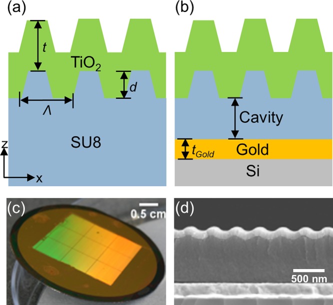
Figures 1a, 1b compare the structure of the cavity-coupled PC biosensor to the solitary PC. Adding a layer of gold under the PC at a specific distance forms the cavity-coupled PC structure. The PC structure is comprised of a periodic linear grating structure (Λ = 360 nm, depth, d = 60 nm) that is patterned in SU8 resist by solvent-assisted soft imprint lithography. A blanket deposition of a TiO2 film (thickness, t = 120 nm) is applied by sputtering on top of the imprinted structure. In previous work, we have shown that an optimal design for PC enhanced fluorescence utilizes transverse magnetic (TM) polarized light (polarization perpendicular to grating direction) for normal excitation and transverse-electric (TE) polarized light (polarization parallel to grating direction) for extraction of the emitted fluorescence signal.8 Therefore, the PC resonance was designed to be at normal-incidence excitation (θ = 0°) for TM polarized light from a λ = 632.8 nm, He-Ne laser for fluorescence excitation. The geometry of the structure and the indices of the surrounding dielectric media determine the resonance wavelength of the PC. The optical cavity strongly modifies these PC resonances. Here a 1D-PC, formed by a linear grating structure in low refractive index (RI) polymer with high RI TiO2 on top, optically couples constructively or destructively to the modes of the underlying optical cavity formed between the PC and the gold layer that acts as a mirror underneath the PC. Figure 1c shows a large area optical image of the cavity-coupled PC fabricated on a 2 in. silicon wafer. Figure 1d shows a cross-sectional scanning electron microscope (SEM) image of the fabricated device with the underlying cavity.
Figure 1.

(a) and (b) Cross-sectional schematic (not to scale) of the PC compared to the cavity-coupled PC. (c) Large area optical image of the cavity-coupled PC fabricated on 2 in. gold coated Si wafer. (d) Cross-sectional SEM image of the cavity-coupled PC showing 1D grating in SU8 coated with TiO2, SU8 cavity, and gold layer on a Si substrate.
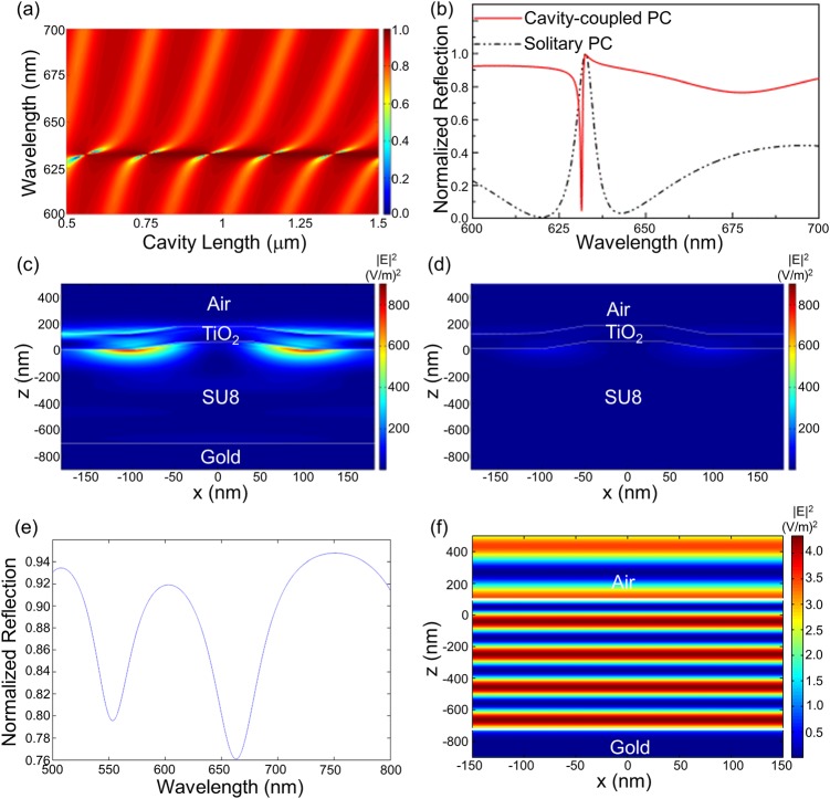
RCWA simulations (RSOFT, Inc.) were performed to model the coupling between the optical cavity and the PC. Figure 2a shows far-field reflection spectra computed by RCWA for a cavity-coupled PC for different lengths of the cavity and the incidence angle of θ = 0° that corresponds to the resonance coupling angle of the PC. The coupling region is represented in dark blue in the plot where the reflection from the device becomes minimum. This represents the region where the incident photon resonates within the cavity before it is either scattered or absorbed by the structure. From the figure, we can see that the coupled mode repeats itself for every ∼220 nm of added cavity length. This length corresponds to ∼λeff/2 that satisfies the condition for constructive interference within the cavity. Here, λeff = λ/neff is the effective PC resonance wavelength in the cavity. Thus, the PC resonances repeat with the changes in the cavity length as they come into and out of overlap with the cavity modes. Figure 2b shows one such reflection spectra for a cavity-length of 740 nm in comparison to a solitary PC reflection spectrum. With the resonant photon now trapped inside the cavity resulting in a strong sharp dip in the reflection, the cavity not only inverts the reflection response of the device but also enhances the resonance as seen by the increase in the evanescent electric fields on the surface of the PC (Figs. 2c, 2d).
Figure 2.
RCWA simulated data for one period of the PC. (a) Far-field reflection of the cavity-coupled PC for various cavity lengths. The incidence angle is θ = 0°, which corresponds to the resonance angle of the PC. (b) Far-field reflection spectrum for one cavity length (740 nm) showing the coupling compared to that of the solitary PC. (c) and (d) Near-field electric field intensity distribution for the cavity-coupled PC and the solitary PC at the resonance wavelength showing enhanced fields for the case of the coupled modes. (e) Far-field reflection spectrum for the un-corrugated structure for one cavity length (740 nm). (f) Near-field electric field intensity distribution for the un-corrugated structure at the reflection dip corresponding to λ ∼ 660 nm.
Figures 2e, 2f show the simulated reflection and field intensity for an un-corrugated structure (no PC). As seen clearly from the figures, without the PC, the structure just behaves like a weak Fabry-Perot cavity without strong evanescent fields. Hence the sharp resonance and the resulting strong evanescent fields are due to the coupling of the 1D PC modes to the modes of the underlying Fabry-Perot type optical cavity.
The subwavelength grating was fabricated by solvent-assisted soft imprint lithography.9 A soft stamp with a negative surface structure of the finished grating was used for imprinting. The stamp was prepared by spin coating Hard-PDMS (a mixture of poly(7%–8%vinylmethylsiloxane)-(dimethylsiloxane), 1,3,5,7-tetravinyl-1,3,5,7-tetramethylcyclotetrasiloxane, Xylene, and poly(25%-30% methylhydrosiloxane)-(dimethylsiloxane)) onto an 8-in. diameter silicon “master” wafer that had been previously prepared with a positive surface structure of the finished device grating by deep UV lithography. After spin-coating the Hard-PDMS on the silicon wafer, a thick layer of Soft-PDMS (10:1 Sylgard 184) was poured over it to provide mechanical strength for handling the stamp. The master wafer with both layers of PDMS on top of it was heat cured overnight in an oven at 65 °C. After curing, the stamp was peeled away from the master wafer and cut into smaller squares. The cavity-coupled PC and the solitary PC were fabricated on a 2-in. diameter Si wafer. SU8 2000.5 was chosen as the polymer that forms the low refractive index layer for the PC and also the cavity layer for the cavity-coupled PC. The solvent assisted imprinting process is performed by first spin coating SU8 onto a clean substrate. A 200 nm gold-coated Si wafer served as the substrate for cavity-coupled PC while a bare Si wafer was the substrate for solitary PC. For the case of the solitary PC, ∼1 μm thick SU8 was applied by spin coating in two layers. This ensures that Si reflectivity has no effect on the resonance modes of the PC and the modes are only determined by the refractive index of SU8 (n = 1.46), the refractive index of TiO2 (n = 2.43) and the dimensions of the grating. For the cavity-coupled PC, a SU8 thickness of ∼750 nm was spin-coated onto the wafer. After spin coating, SU8 was prebaked at 75 °C for 2 min. A small amount of ethanol was then used to wet the SU8 surface before pressing the substrate against the stamp. The stamp was pressed upon the SU8 coated wafer until the ethanol evaporated (∼45 min.), after which the stamp was peeled away and the wafer was UV cured for 2 min and then hard baked at 90 °C for 2 min. Finally, TiO2 (thickness, t = 120 nm) was sputtered onto the grating.
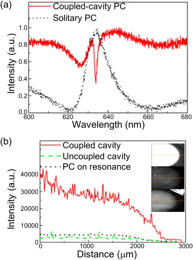
Figure 3a plots the measured far-field reflection for the cavity-coupled PC for the cavity length of 750 nm and the solitary PC with the incidence angle of the white light at θ = 0°. The reflection spectra were collected by a fiber-coupled collimating lens with its distal end connected to a spectrometer with a wavelength resolution of 0.06 nm (Ocean Optics HR 4000). The measured spectra indicate that the presence of the cavity beneath the PC results in an inversion of the resonance characteristic from a reflective maxima to a reflective minima, as predicted by the RCWA model.
Figure 3.

(a) Experimental far-field reflection for the cavity-coupled PC at the cavity length of 750 nm and the solitary PC. The incidence angle for the laser is θ = 0° which corresponds to the resonance angle of the PC. (b) Intensity profile for PPL-Alexa 647 dye for the 3 devices (inset shown in same color scale): Cavity-coupled PC with the cavity length of 750 nm, uncoupled cavity and the PC for the cavity length of 650 nm, and the solitary PC.
In order to demonstrate the enhancement in the signal to noise ratio (SNR) detection of surface attached fluorophores on the cavity-coupled PC surface, a detection experiment using a dye-labeled protein was performed. 0.7 μl volume of the dye-labeled polypeptide, Alexa 647-Poly-Phe-Lysine (PPL-Alexa 647) was applied using a pipette at a concentration of 30 μM on a cavity-coupled PC with resonance cavity length of 750 nm, a cavity-coupled PC with a non-resonant cavity length of 650 nm, and the solitary PC surface. After overnight incubation, the devices were washed by gently dipping them in deionized water for 60 s. Each spot of fluorophore-tagged protein has a diameter of approximately 4 mm. Fluorescent images of the labeled protein spots were obtained using a commercially available confocal laser scanner (Tecan, LS-Reloaded) equipped with a TM polarized λ = 632.8 nm He-Ne laser. The angle of incidence of the laser can be tuned from θ = 0° to θ = 25° and using a numerical aperture of 0.04 to focus the light, only a portion of the illumination is applied at the resonant coupling condition, as discussed in Chaudhery et al.10 The measured images were analyzed by image processing software (imagej). Figure 3b plots the intensity cross section through the dye-labeled protein spot on each device structure. The angle of incidence for the laser was θ = 0° to correspond with the resonance coupling angle of the PC. The fluorescence intensity on the cavity-coupled PC is higher than both the solitary PC and the PC with underlying off-resonance cavity length, showing that the increase in the evanescent fields due to the coupling of the two modes gives rise to the enhancement. From the intensity plot, the increase in the signal to noise ratio for the dye labeled polypeptide on the cavity-coupled PC was calculated as 6× when compared to the solitary PC and 10× when compared to the off-resonant cavity PC. The noise here is defined as the standard deviation in the background intensity around the spot.
In summary, we have demonstrated an approach in which a one-dimensional PC coupled to an underlying Fabry-Perot type cavity has been used to further amplify the available surface electric field for PC enhanced fluorescence. We show that the underlying optical cavity, when coupled to the PC resonance, results in increase of the evanescent field intensity on the surface of the PC as shown by the improvement in the signal intensity of a dye labeled protein. An attractive aspect of this type of cavity-coupled photonic component is that its properties can be tuned dynamically by changing either the dimensions or the refractive index of the cavity. For example, we can go from using a PC as a narrow wavelength reflective filter to narrow wavelength absorptive filter by coupling it to the cavity. This approach shows promise as a method for further increasing the signal-to-noise ratios obtainable for a wide variety of surface-based fluorescence assays used in molecular diagnostics, genomics, and proteomics.
Acknowledgments
This work was supported by the National Institute of Health (R01 GM086382) and the National Science Foundation (CBET 07-54122). Any opinions, findings, conclusions, or recommendations expressed in this material are those of the authors and do not necessarily reflect the views of National Institutes of Health or the National Science Foundation. The authors thank the staff at the Micro and Nanotechnology Laboratory at the University of Illinois at Urbana-Champaign.
References
- Lakowicz J. R., Anal. Biochem. 298, 1 (2001). 10.1006/abio.2001.5377 [DOI] [PMC free article] [PubMed] [Google Scholar]
- Le Moal E., Fort E., Leveque-Fort S., Cordelieres F. P., Fontaine-Aupart M.-P., and Ricolleau C., Biophys. J. 92, 2150 (2007); 10.1529/biophysj.106.096750 [DOI] [PMC free article] [PubMed] [Google Scholar]; Estrada L. C., Martinez O. E., Brunstein M., Bouchoule S., Le-Gratiet L., Talneau A., Sagnes I., Monnier P., Lvenson J. A., and Yacomotti A. M., Opt. Express 18(4), 3693 (2010); 10.1364/OE.18.003693 [DOI] [PubMed] [Google Scholar]; Kinkhabwala A., Yu Z., Fan S., Avlasevich Y., Müllen K., and Moerner W. E., Nat. Photonics 3, 654 (2009); 10.1038/nphoton.2009.187 [DOI] [Google Scholar]; Tawa K., Hori H., Kintaka K., Kiyosue K., Tatsu Y., and Nishii J., Opt. Express 16(13), 9781 (2008). 10.1364/OE.16.009781 [DOI] [PubMed] [Google Scholar]
- Fan S. and Joannopoulos J. D., Phys. Rev. B 65, 235112 (2002); 10.1103/PhysRevB.65.235112 [DOI] [Google Scholar]; Willets K. A. and Van Duyne R. P., Annu. Rev. Phys. Chem. 58, 267 (2006); 10.1146/annurev.physchem.58.032806.104607 [DOI] [PubMed] [Google Scholar]; Anger P., Bharadwaj P., and Novotny L., Phys. Rev. Lett. 96(11), 113002 (2006); 10.1103/PhysRevLett.96.113002 [DOI] [PubMed] [Google Scholar]; Hori H., Tawa K., Kintaka K., Nishii J., and Tatsu Y., Opt. Rev. 16(2), 216 (2009). 10.1007/s10043-009-0040-5 [DOI] [PubMed] [Google Scholar]
- Ganesh N., Zhang W., Mathias P. C., and Cunningham B. T., Nat. Nanotechnol. 2(8), 515 (2007); 10.1038/nnano.2007.216 [DOI] [PubMed] [Google Scholar]; Ganesh N., Mathias P. C., Zhang W., and Cunningham B. T., J. Appl. Phys. 103, 083104 (2008); 10.1063/1.2906175 [DOI] [Google Scholar]; Pokhriyal A., Lu M., Chaudhery V., Huang C.-S., Schulz S., and Cunningham B. T., Opt. Express 18(24), 24793 (2010). 10.1364/OE.18.024793 [DOI] [PMC free article] [PubMed] [Google Scholar]
- Cunningham B. T., Lin B., Qui J., Li P., Pepper J., and Hugh B., Sens. Actuators B 85, 219 (2002) 10.1016/S0925-4005(02)00111-9; [DOI] [Google Scholar]; Pokhriyal A., Lu M., Huang C.-S., Schulz S., and Cunningham B. T., Appl. Phys. Lett. 97(12), 121108 (2010) 10.1063/1.3485672. [DOI] [PMC free article] [PubMed] [Google Scholar]
- Boroditsky M., Krauss T. F., Coccioli R., Vrijen R., Bhat R., and Yablonovitch E., Appl. Phys. Lett. 75(8), 1036 (1999) 10.1063/1.124588; [DOI] [Google Scholar]; Erchak A. A., Ripin D. J., Fan S., Rakich P., Joannopoulos J. D., Ippen E. P., Petrich G. S., and Kolodziejski L. A., Appl. Phys. Lett. 78(5), 563 (2000) 10.1063/1.1342048. [DOI] [Google Scholar]
- Chanda D., Shigeta K., Truong T., Lui E., Mihi A., Schulmerich M., Braun P. V., Bhargava R., and Rogers J. A., Nat. Commun. 2, 479 (2011) 10.1038/ncomms1487; [DOI] [PubMed] [Google Scholar]; Schmidt M. A., Yuan Lei D., Wondraczek L., Nazabal V., and Maier S. A., Nat. Commun. 3, 1108 (2012) 10.1038/ncomms2109; [DOI] [PMC free article] [PubMed] [Google Scholar]; Pokhriyal A., Lu M., Ge C., and Cunningham B. T., “ Coupled external cavity photonic crystal enhanced fluorescence,” J. Biophoton. (published online). 10.1002/jbio.201200173 [DOI] [PMC free article] [PubMed]
- Mathias P. C., Wu H.-Y., and Cunningham B. T., Appl. Phys. Lett. 95, 021111 (2009). 10.1063/1.3184573 [DOI] [PMC free article] [PubMed] [Google Scholar]
- Malyarchuk V., Hua F., Mack N., Velasquez V., White J., Nuzzo R., and Rogers J., Opt. Express 13(15), 5669 (2005). 10.1364/OPEX.13.005669 [DOI] [PubMed] [Google Scholar]
- Chaudhery V., Lu M., Pokhriyal A., Schulz S., and Cunningham B. T., IEEE Sens. J. 12(5), 1272 (2011). [Google Scholar]


