Abstract
Blood analysis plays a major role in medical and science applications and white blood cells (WBCs) are an important target of analysis. We proposed an integrated microfluidic chip for direct and rapid trapping WBCs from whole blood. The microfluidic chip consists of two basic functional units: a winding channel to mix and arrays of two-layer trapping structures to trap WBCs. Red blood cells (RBCs) were eliminated through moving the winding channel and then WBCs were trapped by the arrays of trapping structures. We fabricated the PDMS (polydimethylsiloxane) chip using soft lithography and determined the critical flow velocities of tartrazine and brilliant blue water mixing and whole blood and red blood cell lysis buffer mixing in the winding channel. They are 0.25 μl/min and 0.05 μl/min, respectively. The critical flow velocity of the whole blood and red blood cell lysis buffer is lower due to larger volume of the RBCs and higher kinematic viscosity of the whole blood. The time taken for complete lysis of whole blood was about 85 s under the flow velocity 0.05 μl/min. The RBCs were lysed completely by mixing and the WBCs were trapped by the trapping structures. The chip trapped about 2.0 × 10³ from 3.3 × 10³ WBCs.
INTRODUCTION
Blood is a source of information about the functioning of tissues and organs in the body. So blood analysis plays a major role in medical and science applications. Blood includes plasma, red blood cells (RBCs), platelets, and white blood cells (WBCs). Plasma and WBCs are often the targets of analysis.1 Prior to analysis of DNA in WBCs, it needs to separate WBCs from whole blood for precision and accuracy.2, 3 The separation of WBCs from whole blood is commonly accomplished by conventional off-chip separation methods such as centrifugation and selective lysis of RBCs.1 These methods are time-consuming and require much blood sample. Microfluidics has already been used in chemical and biological analysis,4, 5 cell analysis and clinical diagnostic,6, 7 immunoassay,8 drug discovery,9 material synthesis10, 11 and environmental monitoring.12, 13 However, on-chip separation and analysis of WBCs still face challenges.14
For cell separation, many different methods have been used in the current microfluidic devices.15 In a microchannel, deformable RBCs migrate axially to the channel centre and other cell types (bacteria, platelets, and leukocytes) flow towards the channel sides. Hou et al. reported a simple microfluidic approach for microbial from whole blood using this phenomenon.16 Furlani presented a microfluidic system for separation of red and white blood cells in plasma using magnetic method, which is composed of an array of integrated soft-magnetic element.17 However, some oxygenated RBCs exhibit diamagnetic characteristics like WBCs.18 Jones et al. used constant potential insulator-based gradient dielectrophoresis in a converging, sawtooth-patterned microchannel to separate cells from the matrix of whole blood.19 They trapped RBCs from samples of human blood under a direct current (DC) field by exploiting variations in their characteristic physical properties. Deterministic lateral displacement (DLD) offers a method to separate larger cells from smaller cells.20, 21 But RBC assumes a biconcave discoid shape with a diameter of about 8 μm and WBC is spherical with a diameter of about 8 μm.22 Chen et al. proposed a crossflow filtration chip to separate blood cells that successfully avoided clogging or jamming.22 Sun et al. presented a double spiral microfluidic device to separate particles or cells by the competition between the inertial lift force and Dean drag force and separated of HeLa and 20× diluted blood samples at the initial tumor-to-blood cell ratio of 8 × 10−7.23 It is difficult to integrate with the subsequent steps because the method needs the same pressure of the two outlets. In addition, separation of WBCs from whole blood is only the first step. So trapping WBCs after separation on chip can enhance the quality of analysis and reduce noise in data.
With the development of advanced microfabrication technologies, hydrodynamic method provides a new research tool for cell trap.24 Zhang et al. obtained uniform murine embryonic fibroblast cells loading and distribution with the help of the microsieves.25 Faley et al. designed and fabricated the microfluidic cell trap device consisting in bucket-like structures opposing the direction of flow to trap CD4 + T cells.26 Chung et al. proposed a highly efficient single cell trap structure with hydrodynamic guiding, which has a capacity to place individual cells into separated microwells.27 Xu et al. proposed a microfluidic microsphere-trap array device and built a comprehensive, robust, and simple framework to optimize the values of the geometric parameters to maximize the packing density.28 However, the apertures with large aspect ratio are easily damaged when the polydimethylsiloxane (PDMS) layer is peeled from the mold. Especially, Di Carlo et al. designed a two-layer structure to make fabrication easily.29 But WBCs exist at low concentration in blood samples, typically several percent of RBCs in quantity.1 So it needs to integrate a RBCs separation or elimination functional unit with WBCs trapping unit for rapid trapping WBCs from whole blood directly.
In this paper, we presented an integrated microfluidic chip for direct trapping of white blood cells from whole blood. The chip consists of two basic functional units: a winding channel to mix and arrays of two-layer trapping structures to trap. RBCs were eliminated through moving the winding channel and then WBCs were trapped by the arrays of trapping structures. The performance of mixing efficiency was tested by using tartrazine and brilliant blue water. Then we lysed the RBCs complete under the flow velocity 0.05 μl/min and trapped RBCs by trapping structures.
THEORY OF MIXING
The fluid flow within the winding channel is laminar due to small dimension of the device and slow flow rate of the fluid. It can be characterized by a Reynolds number, which represents the ratio between momentum and viscous friction. The Reynolds number can be expressed30
| (1) |
where u, Dh, and v are flow velocity, hydraulic diameter, and kinematic viscosity, respectively. A high Reynolds number above a critical value (around 2300) indicates a turbulent flow. Mixing in microfluidic channels is dictated by passive molecular diffusions in laminar. The time of complete mixing can be easily estimated from a simple diffusion equation31
| (2) |
where T is the diffusion time of a molecule to diffuse over a distance L and D is the diffusion coefficient of the molecule in solution.
The distance (l) of the liquid flows through within the diffusion time can be expressed
| (3) |
The distance (l) is strongly dependent on the flow velocity. By controlling the flow velocity of each fluid, a complete mixing of two components can be realized in this current design.
MATERIALS AND METHODS
Chip fabrication
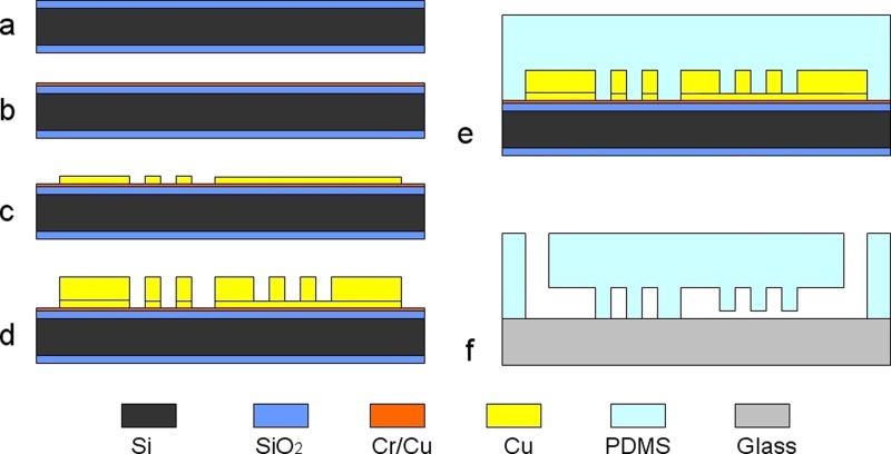
The microfluidic chip was fabricated in the biologically compatible PDMS6, 32 by soft lithography, as shown in Fig. 1. First, a 480 μm thickness double-side polished oxidized silicon wafer was chosen as the substrate, as shown in Fig. 1a. A Cr/Cu seed layer was sputtered on the silicon wafer for the subsequent electroforming, as shown in Fig. 1b. Then silicon wafer was spin coated with positive photoresist about 5 μm in thickness and patterned. Cu about 3 μm in thickness was electroformed to fabricate the channel and pillars of trapping structures, as shown in Fig. 1c. The wafer was spin coated with positive photoresist about 15 μm in thickness and patterned again. Cu about 12 μm in thickness was electroformed to fabricate the channel and U shaped compartments of trapping structures. The mother mold with inverse structures was fabricated after removal of the photoresist, as shown in Fig. 1d. Then, PDMS prepolymer was poured over the mother mold and baked at 70 °C for 3 h, as shown in Fig. 1e. After PDMS was released from the mold and punched through to function as inlets/outlet for sample injection and extraction, PDMS was bonded with a glass slide after oxygen plasma treatment, as shown in Fig. 1f.
Figure 1.
Fabrication process of the chip. (a) A Si wafer; (b) sputtering a Cr/Cu seed layer; (c) electroforming Cu; (d) electroforming Cu; (e) transferring the structure to PDMS; and (f) punching inlets/outlet and bonding PDMS and a glass slide.
Tartrazine and brilliant blue water mixing
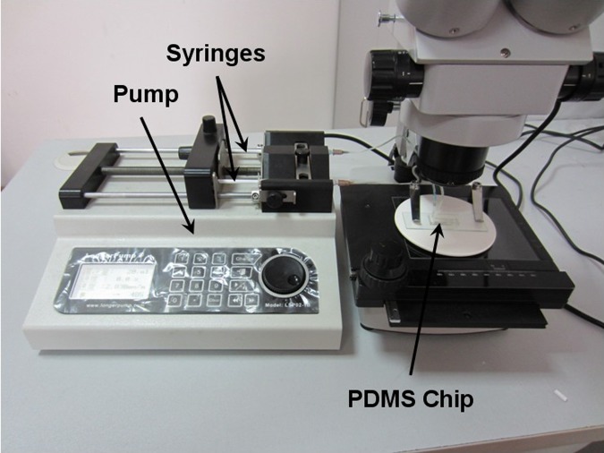
To evaluate the mixing effect of the chip, the tartrazine water and brilliant blue water were used as components to be mixed in the winding channel. They were formed by dissolving tartrazine and brilliant blue food additives colors in water. The concentrations of them are 5 mg/ml and 2.5 mg/ml. Experimental setup was shown in Fig. 2. The microfluidic chip was connected to a syringe pump system to control the fluid flows, which included two syringes for tartrazine water and brilliant blue water, respectively. The tartrazine and brilliant blue water were mixed in the winding channel after they were injected into the chip and tested under a microscope.
Figure 2.
Experimental setup for tartrazine and brilliant blue water mixing.
WBCs trapping
To evaluate the effect of WBCs trapping from whole blood, mouse blood and red blood cell lysis buffer were used as components to be tested for the WBCs trapping. The mouse blood was diluted to triple of the original using Dulbecco's phosphate buffered saline (PBS) to make that the concentration ratio of the red blood cell lysis buffer and the original whole blood was 3:1. The microscope was replaced with an inverted fluorescence microscope in WBCs trapping test. The blood and red blood cell lysis buffer were injected into the chip in 20 min. The DAPI (4′,6-diamidino-2-phenylindole) staining was used to see WBCs clearly in the fluorescence microscope. The concentration of blood cells was determined using blood cell counting plate. The concentrations of the RBCs and WBCs in the original whole blood were 9 × 10⁶/μl and 1 × 10⁴/μl, respectively.
RESULTS AND DISCUSSION
Mold characterization
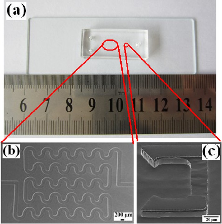
The chip was fabricated successfully using soft lithography, as shown in Fig. 3. The winding channel for RBCs lysis within and trapping structures for WBCs trapping are shown in Figs. 3b, 3c. The winding channel (height: 15 μm) is a serpentine channel, which was connected with 52 semi-circular pipes (width: 200 μm). The length of the winding channel is about 44 mm. The trapping structures (490 in the chip) include two layers. The upper layer (height: 12 μm) is a U-shaped compartment with sharp corners at the fore-end. The bottom layer consists of spacers to create small gap (height: 3 μm) between the upper layer and the glass, which enables the flow of the solution through the trap structures but keeps the cells in the structures. Different sizes of cells can be trapped easily by changing the height of the pillars during the first electroforming Cu.
Figure 3.
(a) Photographs of the chip; (b) SEM photo of the winding channel, and (c) SEM photo of the trapping structure.
Tartrazine and brilliant blue water mixing
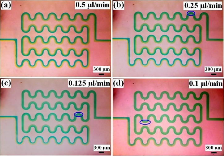
Mixing within the device with different flow velocities using tartrazine and brilliant blue water is shown in Fig. 4. Mixing of the two fluids would result in the color change within the mixed region, and the intensity of the color change can be used to estimate mixing effect. Under the flow velocities 0.5 μl/min (Re = 0.15), the mixture flowed through the winding channel within 8 s. The tartrazine and brilliant blue water cannot be mixed through diffusion within the winding channel. This normally requires a significantly longer time to mix well within the winding channel. Under the flow velocities 0.25 μl/min (Re = 0.075), 0.125 μl/min (Re = 0.038), and 0.1 μl/min (Re = 0.03), the mixing times were 17 s, 18 s, and 20 s, respectively. The three values are different due to visual differences. Thus, the tartrazine water and brilliant blue water can mix well within the winding channel when the flow velocity is smaller than 0.25 μl/min.
Figure 4.
Tartrazine and brilliant blue water mixing under different flow velocities (blue ring is the starting of complete mixing). (a) 0.5 μl/min; (b) 0.25 μl/min; (c) 0.125 μl/min; and (d) 0.1 μl/min.
WBCs trapping
It requires more than 5 min of incubation time to ensure 100% lysis of WBCs in traditional experimental methods.33 Though the process of lysis itself only requires 20–30 s, the time required for complete diffusion of the red blood cell lysis buffer (to ensure 100% lysis) is longer.34 It needs to reduce the lysis time to avoid the influence on WBCs. The time required for complete lysis depends on the time required for uniform diffusion, which depends on the flow velocity for a specific structure.
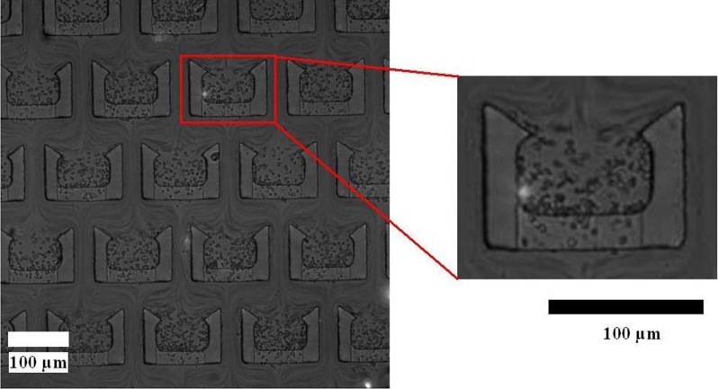
According to the result of the tartrazine and brilliant blue water mixing, the flow velocity 0.25 μl/min (Re = 0.023 ∼ 0.075, 0.023 and 0.075 are the Reynolds number valves of pure whole blood and pure red blood cell lysis buffer in the channel, respectively. The Reynolds number of the mixing is in the range of the two values.) was first used to test the whole blood and the red blood cell lysis buffer. Many remaining RBCs that were not lysed by the red blood cell lysis buffer flowed into the trapping functional unit, as shown in Fig. 5. It indicates the whole blood and red blood cell lysis buffer did not mix well in the winging channel. The flow velocity of complete mixing in the whole blood and red blood cell lysis buffer is lower than it in the tartrazine and brilliant blue water. This can be explained from diffusion coefficient. RBC has smaller diffusion coefficient because of larger volume.35 In addition, whole blood has higher kinematic viscosity than water. So the RBC is more difficult to diffuse in whole blood. This normally requires a significantly longer time or lower flow velocity according to Eq. 3. Some RBCs trapped in the structures flowed through the 3 μm gap between PDMS and glass. RBC at rest assumes a biconcave discoid shape with a diameter of ∼8 μm and a thickness of ∼2 μm. So RBCs can flow through the 3 μm gap easily.
Figure 5.
WBCs trapping under the flow velocity 0.25 μl/min.
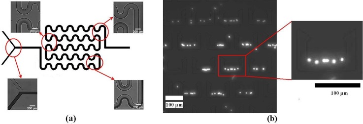
Lysis efficiency of red blood cells in the channel under the flow velocity 0.05 μl/min is shown in Fig. 6a. Based on the total flow velocity and the location in the channels where complete lysis was observed, the time taken for complete lysis of WBCs could be calculated. The percentage lysis of WBCs as a function of distance traveled in the channel is plotted in Fig. 6a. The distance traveled at WBCs complete lysis was about 47 mm. So the time taken for complete lysis of whole blood was about 85 s. It can reduce the mixing time by decreasing the width of the channel.34 Increasing the height of the channel can enhance the yield of WBCs.
Figure 6.
(a) Lysis efficiency of red blood cells in the microfluidic channel and (b) WBCs trapping under the flow velocity 0.05 μl/min.
The flow velocity was decreased to 0.05 μl/min (Re = 0.005 ∼ 0.015), and there are almost no RBCs in the trap structures, as shown in Fig. 6b. It indicates that the whole blood and red blood cell lysis buffer mixed completely in the winging channel. The diameter of WBC is about 8 μm. So it is not easy to flow through the 3 μm gap for RBCs. The chip had 490 trapping structures, and each trap structure trapped 4 cells on average. So the chip trapped about 2.0 × 10³ WBCs. The trap efficiency was about 60%. It can further enhance the trap efficiency by decreasing the space between the structures.
CONCLUSIONS
We introduced an integrated microfluidic chip for rapid trapping WBCs from whole blood directly. The chip, fabricated in the biologically compatible PDMS, consists of two basic functional units: a winding channel to mix and arrays of two-layer trapping structures to trap. The tartrazine and brilliant blue water can mix well within the winding channel when the flow velocity is smaller than 0.25 μl/min. And the flow velocity of complete mixing in the whole blood and red blood cell lysis buffer is 0.05 μl/min. RBCs in whole blood has diffusion coefficient due to larger volume and higher kinematic of the whole blood. The time taken for complete lysis of whole blood was about 85 s. The RBCs were lysed completely by mixing and the WBCs were trapped (60%) by the trapping structures under the flow velocity 0.05 μl/min.
ACKNOWLEDGMENTS
This work was financially supported by Ministry of Science and Technology of China (No. 2010CB933901) and Science and Technology Innovation fund of SJTU – University of Michigan.
References
- Toner M. and Irimia D., Annu. Rev. Biomed. Eng. 7, 77 (2005). 10.1146/annurev.bioeng.7.011205.135108 [DOI] [PMC free article] [PubMed] [Google Scholar]
- Bhagat A. A. S., Bow H., Hou H. W., Tan S. J., Han J., and Lim C. T., Med. Biol. Eng. Comput. 48, 999 (2010). 10.1007/s11517-010-0611-4 [DOI] [PubMed] [Google Scholar]
- Kim M., Jung S. M., Lee K. H., Kang Y. J., and Yang S., Artif. Organs 34, 996 (2010). 10.1111/j.1525-1594.2010.01114.x [DOI] [PubMed] [Google Scholar]
- Demello A. J., Nature 442, 394 (2006). 10.1038/nature05062 [DOI] [PubMed] [Google Scholar]
- Chen J. D., Chen D., Xie Y., Yuan T., and Chen X., Nano-Micro Lett. 5, 66 (2013). 10.3786/nml.v5i1.p66-80 [DOI] [Google Scholar]
- Cui S. Y., Liu Y. P., Wang W., Sun Y., and Fan Y. B., Biomicrofluidics 5, 032003 (2011). 10.1063/1.3623411 [DOI] [PMC free article] [PubMed] [Google Scholar]
- Ishikawa T., Fujiwara H., Matsuki N., Yoshimoto T., Imai Y., Ueno H., and Yamaguchi T., Biomed. Microdevices 13, 159 (2011). 10.1007/s10544-010-9481-7 [DOI] [PubMed] [Google Scholar]
- Du N., Chou J., Kulla E., Florianob P. N., Christodoulidesb N., and McDevittb J. T., Biosens. Bioelectron. 28, 251 (2011). 10.1016/j.bios.2011.07.027 [DOI] [PMC free article] [PubMed] [Google Scholar]
- Dittrich P. S. and Manz A., Nat. Rev. Drug Discovery 5, 210 (2006). 10.1038/nrd1985 [DOI] [PubMed] [Google Scholar]
- Song J., Hormes J., and Kumar C. S. S. R., Small 4, 698 (2008). 10.1002/smll.200701029 [DOI] [PubMed] [Google Scholar]
- Ji X. H., Cheng W., Guo F., Liu W., Guo S. S., He Z. K., and Zhao X. Z., Lab Chip 11, 2561 (2011). 10.1039/c1lc20150f [DOI] [PubMed] [Google Scholar]
- Gardeniers J. G. E. and Van den Berg A., Anal. Bioanal. Chem. 378, 1700 (2004). 10.1007/s00216-003-2435-7 [DOI] [PubMed] [Google Scholar]
- Yamaguchi N., Torii M., Uebayashi Y., and Nasu M., Appl. Environ. Microbiol. 77, 1536 (2011). 10.1128/AEM.01765-10 [DOI] [PMC free article] [PubMed] [Google Scholar]
- Choi S., Song S., Choi C., and Park J. K., Lab Chip 7, 1532 (2007). 10.1039/b705203k [DOI] [PubMed] [Google Scholar]
- Nilsson J., Evander M., Hammarström B., and Laurell T., Anal. Chim. Acta 649, 141 (2009). 10.1016/j.aca.2009.07.017 [DOI] [PubMed] [Google Scholar]
- Hou H. W., Gan H. Y., Bhagat A. A. S., Li L. D., Lim C. T., and Han J., Biomicrofluidics 6, 024115 (2012). 10.1063/1.4710992 [DOI] [PMC free article] [PubMed] [Google Scholar]
- Furlani E. P., J. Phys. D: Appl. Phys. 40, 1313 (2007). 10.1088/0022-3727/40/5/001 [DOI] [Google Scholar]
- Melville D., Paul F., and Roath S., Nature 255, 706 (1975). 10.1038/255706a0 [DOI] [PubMed] [Google Scholar]
- Jones P. V., Staton S. J. R., and Hayes M. A., Anal. Bioanal. Chem. 401, 2103 (2011). 10.1007/s00216-011-5284-9 [DOI] [PubMed] [Google Scholar]
- Green J. V., Radisic M., and Murthy S. K., Anal. Chem. 81, 9178 (2009). 10.1021/ac9018395 [DOI] [PubMed] [Google Scholar]
- Liu Z. B., Huang F., Du J. H., Shu W. L., Feng H. T., Xu X. P., and Chen Y., Biomicrofluidics 7, 011801 (2013). 10.1063/1.4774308 [DOI] [PMC free article] [PubMed] [Google Scholar]
- Chen X., Cui D. F., Liu C. C., and Li H., Sens. Actuators B 130, 216 (2008). 10.1016/j.snb.2007.07.126 [DOI] [Google Scholar]
- Sun J. S., Liu C., Li M. M., Wang J. D., Xianyu Y. L., Hu G. Q., and Jiang X. Y., Biomicrofluidics 7, 011802 (2013). 10.1063/1.4774311 [DOI] [PMC free article] [PubMed] [Google Scholar]
- Karimi A., Yazdi S., and Ardekani A. M., Biomicrofluidics 7, 021501 (2013). 10.1063/1.4799787 [DOI] [PMC free article] [PubMed] [Google Scholar]
- Zhang B. Y., Kim M. C., Thorsen T., and Wang Z., Biomed. Microdevices 11, 1233 (2009). 10.1007/s10544-009-9342-4 [DOI] [PubMed] [Google Scholar]
- Faley S., Seale K., Hughey J., Schaffer D. K., VanCompernolle S., McKinney B., Baudenbacher F., Unutmaz D., and Wikswo J. P., Lab Chip 8, 1700 (2008). 10.1039/b719799c [DOI] [PMC free article] [PubMed] [Google Scholar]
- Chung J. H., Kim Y. J., and Yoon E., Appl. Phys. Lett. 98, 123701 (2011). 10.1063/1.3565236 [DOI] [PMC free article] [PubMed] [Google Scholar]
- Xu X. X., Sarder P., Li Z. Y., and Nehorai A., Biomicrofluidics 7, 014112 (2013). 10.1063/1.4793713 [DOI] [PMC free article] [PubMed] [Google Scholar]
- Di Carlo D., Wu L. Y., and Lee L. P., Lab Chip 6, 1445 (2006). 10.1039/b605937f [DOI] [PubMed] [Google Scholar]
- Nguyen N. T. and Wu Z. G., J. Micromech. Microeng. 15, R1 (2005). 10.1088/0960-1317/15/2/R01 [DOI] [Google Scholar]
- Beebe D. J., Mensing G. A., and Walker G. M., Annu. Rev. Biomed. Eng. 4, 261 (2002). 10.1146/annurev.bioeng.4.112601.125916 [DOI] [PubMed] [Google Scholar]
- Sia S. K. and Whitesides G. M., Electrophoresis 24, 3563 (2003). 10.1002/elps.200305584 [DOI] [PubMed] [Google Scholar]
- Pelegri C., Rodriguez-Palmero M., Morante M. P., Comas J., Castell M., and Franch A., J. Immunol. Methods 187, 265 (1995). 10.1016/0022-1759(95)00193-1 [DOI] [PubMed] [Google Scholar]
- Sethu P., Anahtar M., Moldawer L. L., Tompkins R. G., and Toner M., Anal. Chem. 76, 6247 (2004). 10.1021/ac049429p [DOI] [PubMed] [Google Scholar]
- Zhang Z. Y., Zhao P., Xiao G. Z., Lin M., and Cao X. D., Biomicrofluidics 2, 014101 (2008). 10.1063/1.2894313 [DOI] [PMC free article] [PubMed] [Google Scholar]


