Abstract
Recent clinical studies of the percutaneous transvenous mitral annuloplasty (PTMA) devices have shown a short-term reduction of mitral regurgitation (MR) after implantation. However, adverse events associated with the devices such as compression and perforation of vessel branches, device migration and fracture were reported. In this study, a finite element analysis was performed to investigate the biomechanical interaction between the proximal anchor stent of a PTMA device and the coronary sinus (CS) vessel in three steps including i) the stent release and contact with the CS wall, ii) the axial pull at the stent connector and iii) the pressure inflation of the vessel wall. To investigate the impact of the material properties of tissues and stents on the interactive responses, the CS vessel was modeled with human and porcine material properties, and the proximal stent was modeled with two different Nitinol materials with one being stiffer than the other. The results indicated that the vessel wall stresses and contact forces imposed by the stents were much higher in human than porcine models. However, the mechanical differences induced by the two stent types were relatively small. The softer stent exhibited a better fatigue safety factor when deployed in the human model than in the porcine model. These results underscored the importance of the CS tissue mechanical properties. Higher vessel wall stress and stent radial force were obtained in human model than those in porcine model, which also brought up questions as to the validity of using porcine model to assess device mechanical function. The quantification of these biomechanical interactions can offer scientific insight into the development and optimization of PTMA device design.
Keywords: minimally invasive, mitral valve repair, coronary vein, PTMA stent, Monarc, tissue-stent interaction
INTRODUCTION
Mitral regurgitation (MR) occurs when mitral valve does not close tightly, resulting in the backward leakage of blood from the left ventricle into the left atrium during systole. It is caused by various structural and functional abnormalities of the mitral valve such as mitral annulus (MA) dilatation, left ventricle dysfunction, papillary muscle displacement, leaflet calcification and myxomatous disease [1]. MR occurs in about 2% of the population with a similar prevalence in males and females [1]. Moderate to severe MR occurs in up to 19% of patients after myocardial infarction and in 15% of patients with dilated cardiomyopathy [2, 3]. In patients with functional MR, a combination of changes in left ventricular and mitral annulus (MA) geometry and function induce leaflet malcoaptation and thereby regurgitation. Surgical treatment of severe functional MR often involves mitral annuloplasty, a procedure where a flexible or rigid annuloplasty ring is used to downsize the dilated mitral valve annulus and improve leaflet apposition by posterior annular correction. However, reported operative mortalities of up to 6 ~12% have limited the more expanded use of this procedure [4-6].
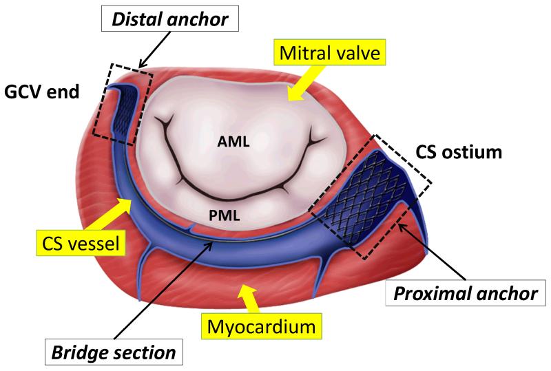
Recently minimally invasive percutaneous transvenous mitral annuloplasty (PTMA) devices have been tested in patients who cannot undergo a surgical procedure involving a thoracotomy. The technique is based on the concept that by utilizing the parallel location of the coronary sinus (CS) vessel to the mitral annulus (MA) (see Fig. 1), a device, that can reshape the annulus, can be percutaneously deployed within the CS and great cardiac vein (GCV). Illustrated in Fig. 1 is one of the PTMA devices, which consists of a proximal anchor, a spring-like bridge segment and a distal anchor. The device is made of self-expanding Nitinol material that is commonly used for stent grafts. The proximal and distal anchors are deployed into the CS ostium and the great cardiac vein (GCV), respectively. The bridge segment is incorporated with a biodegradable suture, which degrades overtime. Thus the bridge segment will shorten and draw the anchors together, thereby displacing the posterior annulus and reducing the septal-lateral mitral annulus distance.
Figure 1.
Illustration of a PTMA being deployed into the coronary sinus (CS) vessel, which is adjacent to the posterior mitral annulus. AML - anterior mitral leaflet. PML - posterior mitral leaflet. GCV - great cardiac vein.
Animal studies have demonstrated the effectiveness of PTMA devices to reduce MR in heart failure induced by rapid pacing in the short-term [7-9]. However, initial human trials were suboptimal. The adverse events included compression of the left circumflex artery, perforation of vessel branches, device migration and device fracture [10-14]. Some of these issues may be improved by a detailed anatomical assessment of the CS and its tributaries prior to the procedure using imaging modalities such as multidetector computed tomography. Device dysfunctions involving device migration and fracture, however, are mainly associated with the biomechanical interaction between CS tissues and the device that is largely unexplored in the literature. In pre-clinical trials of cardiovascular interventional devices, animal results are often used as a guide for device design and development. However, without a quantitative understanding of the difference between animal and human tissues and the associated device-CS tissue interactions, the development of these devices based on ad hoc and trial-and-error approaches can be time-consuming and costly. In the present study, we first established a finite element (FE) study to evaluate the biomechanical responses of the proximal anchor of this PTMA device when interacted with the human and porcine CS walls. In addition, we chose two Nitinol stent materials to investigate the impact of stent material stiffness. The biomechanical interactive properties between the stents and the CS vessels were quantified by measuring the contact forces, vessel wall stresses, strains and fatigue safety factor of stents were analyzed.
MATERIALS AND METHODS
Model geometries
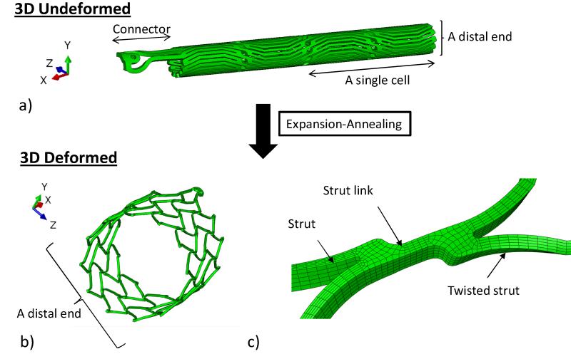
The complete FE model for the stent deployment simulation consists of the proximal stent, the CS vessel, and the stent expanding and crimping sheaths. Geometrical and numerical details of the models are listed in Table 1. The proximal anchor can be thought of as an elastic lattice, deriving its strength from the joints and bending action of component struts. Because of the lack of symmetry in this part, the entire anchor has been modeled. The stent geometry, after the laser cut from a cylindrical Nitinol tube and electroplishing, was 21 mm in length with an inner diameter (ID) of 1.6 mm and a thickness of 0.3 mm, as shown in Fig. 2a. This stent geometry was further deformed, through a series of expansion and annealing process, to an expanded shape as shown in Fig. 2b. Typically, the stent anchor’s diameter is oversized and larger than the CS’s diameter by 2 – 4 mm [15]. Therefore, it was expanded from an ID of 1.6 mm to a targeted ID of 14.90 mm, assuming the CS’s ID is 12 mm. The radial expansion was carried out in the FE simulation by displacing the expanding sheath that placed inside the stent anchor in increments of 3, 4, 6, 8, 12 and 15.50 mm in outer diameter (OD), each followed by an annealing step. The annealing process was simulated using a built-in function in ABAQUS (*anneal) where stent stresses and strains were set to zero. By dividing one large deformation step into several steps of small deformations with an annealing process, the potential damages to the stent that may be caused by large deformations can be effectively reduced. The final deformed geometry of the stent anchor is shown in Fig. 2b, in which it was composed of two strut cells in the axial and twelve in the circumferential directions. The two pairs of stent struts were joined by a strut link (Fig. 2c). Crimping and release of the stent anchor were achieved by displacing the cylindrical crimping sheath located externally of the stent anchor inwardly and outwardly, respectively.
Table 1.
Geometrical and Finite Element modeling measures of all models.
| Dimension (mm) |
||||
|---|---|---|---|---|
| Models | Undeformed | Element type | No. of elements | |
| ID | 12 | |||
| CS | Thickness | 0.74 | C3D8I (*) | 43,199 |
| Length | 60 | |||
| ID | 1.60 | |||
| Stent | Thickness | 0.30 | C3D8I (*) | 114,219 |
| Length | 21 | |||
| ID | 11 | |||
| Sleeve_expand | Thickness | - | M3D4R (†) | 2,231 |
| Length | 41.5 | |||
| ID | 15.52 | |||
| Sleeve_crimp | Thickness | - | M3D4R (†) | 2,231 |
| Length | 41.50 | |||
CS and stent models were meshed with incompatible mode element.
indicates the 8-node hexahedral linear elements
indicates the 4-node quadrilateral elements.
Figure 2.
a) The 3D undeformed shape of the stent prior to expansion-annealing process, showing the connector and the stent body that is composed of 12 struts in the circumferential (z) and 2 in the axial (x) directions; b) the 3D deformed shape of the stent after expansion-annealing process; and c) the two struts of the stent are united by a strut link. The strut is twisted asymmetrically after the process.
A study by El-Maasarany et al. [16] on the anatomy of the CS vessel showed that 80% (32/40 patients) of human specimens had coronary sinus as a cylindrical shape near the opening into the right atrium. Thus, we simplified our CS vessel model to a cylindrical tube, with an inner diameter of 12 mm and a thickness of 0.74 mm [17], to facilitate the comparison between different CS tissues and stent materials.
The 8-node hexahedral linear incompatible mode element (C3D8I) was chosen to mesh both the CS vessel and the stent as C3D8I is preferred for stent analysis due to the nature of bending during loading. The 4-node quadrilateral element (M3D4R) was modeled for the expansion and crimping sheaths. A mesh sensitivity analysis was performed, see appendix A for more details.
Material properties and constitutive modeling
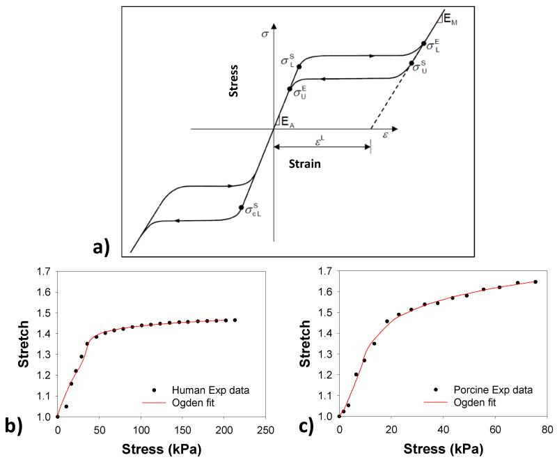
The two different Nitinol materials, Nitinol 1 (N1) and Nitinol 2 (N2), were utilized in the simulations, adopted from Kleinstreuer et al. [18] with modifications. For an isothermal analysis as the one presented here, the stent material model can be defined by a stress-strain curve and “breakpoint” stresses, as shown in Fig. 3-a. The inputs to this model are the two moduli of Elasticity, the plateau transformation strain and the five stress breakpoints. From Table 2, it can be seen that N1 material is stiffer than N2 material with higher austenite (EA) and martensite (EM) moduli.
Figure 3.
a) A typical stress-strain curve for Nitinol material, mean b) human and c) porcine CS stress-stretch curves fitted with the Ogden model.
EA = Austenitic Elastic Modulus
νA = Austenitic Poisson’s ratio
EM = Martensitic Elastic Modulus
νM = Martensitic Poisson’s ratio
εL = Transformation strain
(δσ/δT)L = Loading (δσ/δT) (set to 1.0 for an isothermal analysis)
σSL = Start of transformation stress during loading
σEL = End of transformation stress during loading
T0 = Reference temperature
(δσ/δT)U = Unloading (δσ/δT) (set to 1.0 for an isothermal analysis)
σSU = Start of transformation stress during unloading
σEU = End of transformation stress during unloading
σSCL = Start of transformation stress during compressive loading
Table 2.
The material parameters of CS vessels and stents.
| μ1 (GPa) | a1 | μ2(GPa) | a2 | μ2(GPa) | a2 | ||||||
|---|---|---|---|---|---|---|---|---|---|---|---|
| Human | 127.653 | 5.928 | −63.082 | 11.851 | 4.674 | 19.317 | |||||
| Porcine | 8.213 | 10.608 | 22.689 | −5.748 | −12.515 | 9.184 | |||||
| EA(MPa) | ν A | EM (MPa) |
ν M | ε L | σ S L | σ E L | σ S U | σ E U | σ S CL | T | |
| Nitin-1 | 70,000 | 0.3 | 47,800 | 0.3 | 0.063 | 600 | 670 | 288 | 254 | 900 | 37 |
| Nitin-2 | 40,000 | 0.3 | 18,554 | 0.3 | 0.04 | 390 | 425 | 140 | 135 | 585 | 37 |
The mechanical properties of the coronary sinus of both human and porcine were obtained from the pressure-inflation tests of porcine (n = 7, 6-9 months old) [19] and human (n = 4, 85.25 ± 7.41 years old) CS vessels. Briefly, the human CS vessels were subjected to the mechanical test while they were intact (i.e. the CS vessel was not dissected out of the heart). After 10 preconditioning cycles, the vessels were incrementally dilated up to 80 mmHg of pressure. The dilated CS diameters were measured to obtain the CS pressure-radius curve, from which the hoop/axial stress-stretch relation were calculated [19]. We chose the Ogden isotropic nonlinear hyperelastic model [20] to characterize the experimental data,
| (1) |
where μi and ai are the material constants and λi are the principal stretches. The mean data from four human and seven porcine specimens were fitted with the Eq.1 to obtain the material parameters. The goodness of fit was determined using R-square value based on the Levenberg-Marquardt nonlinear regression algorithm using SYSTAT 10 (Systat Software Inc., Chicago, IL). The Ogden model curve fitting results for both human and porcine tissues are illustrated in Fig. 3-b & c.
Tissue-stent interaction (TSI) simulation and boundary conditions
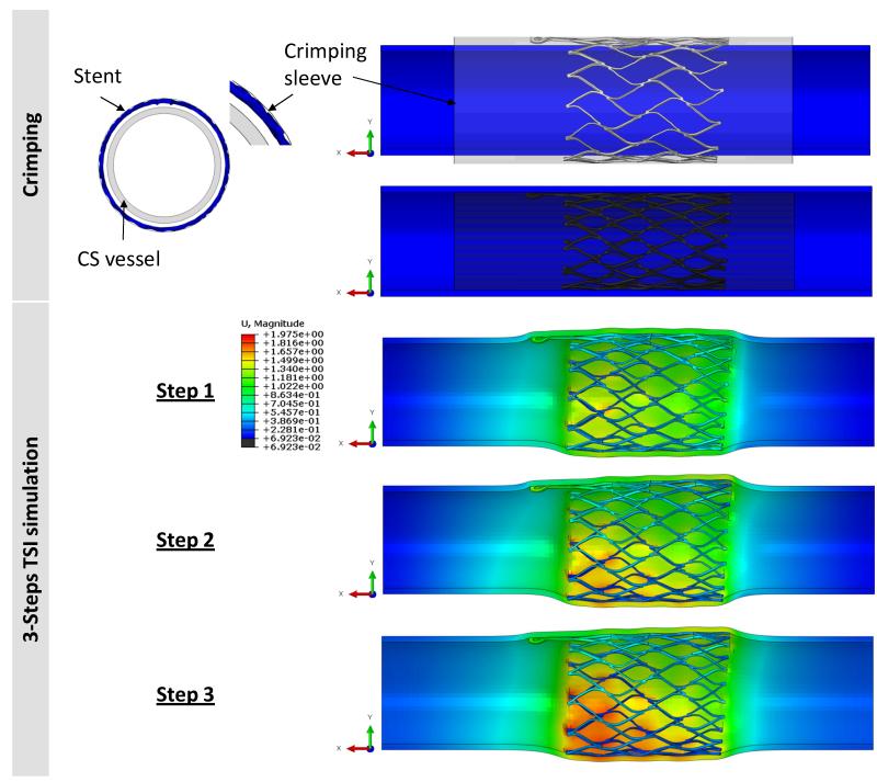
The expanded geometry of the stent was crimped in a catheter prior to the PTMA deployment. In the simulation, the stent was crimped to an OD of 11.98 mm using a displacement-controlled deformation of the crimping sheath, see Fig. 4. After the stent release and deployment in the CS vessel, the biomechanical interaction between the device and the CS wall is rather complex. Here, we briefly described the procedure and interactive forces involved: The proximal stent anchor is released from the delivery catheter and deployed into the CS ostium. The expansion of the stent generates contact forces between the CS tissue and the stent, which enable anchoring of the stent to the CS wall. A biodegradable suture keeps the bridge links “open” and elongated; upon dissolution, the links close, the bridge length is reduced and the proximal and distal stent anchors are brought closer together, reshaping and reducing the mitral annulus in the septal-lateral distance. Therefore, the bridge segment will impose an axial force on the proximal stent. In addition, an internal venous pressure of 10 mmHg will also deform the CS wall and affect the stent-tissue interaction. The major biomechanical loading steps in this process are illustrated in Fig. 4. In the simulation, we developed three corresponding steps as follows:
Figure 4.
(Top) The crimping process was carried out by applying displacement control on the crimping sheath to decrease the diameter of the stent to less than 12 mm. (Bottom) The 3-step TSI simulation: step-1: release the crimping sheath, step-2: apply an axial load of 2.45 N, and step-3: apply a pressure of 10 mmHg to the inner wall of CS.
Step 1 – Contact between CS wall and stent anchor during the stent deployment. The contact was established by removing the crimping sheath to release the proximal anchor to contact with the CS inner wall.
Step 2 – Effect of axial contraction force due to the bridge contraction. An axial load with a magnitude of 2.45 N in the axial direction was applied to the connector elements to approximate the pulling force generated by the contraction of the bridge section that occurs upon dissolving of the biodegradable suture [21].
Step 3 – Deformation due to the pulsatile blood pressure in the CS vessel. An incremental pressure, from 0 to 10 mmHg, was imposed on the luminal surface of the CS wall to mimic the physiological condition.
The coefficient of friction between the stent and CS inner wall contact surfaces was set to 0.1 in steps 1 and 2. For step 3, the contact definition was set as a non-slipping condition (an ABAQUS option: ROUGH) to imitate the effect of long-term tissue in-growth in-between the stent struts. The FE analysis was performed with the ABAQUS/Explicit release 6.11 on a high performance computing (HPC) Linux cluster with Intel Xeon X5650 Westmere cores. The following output variables were analyzed in each of the three steps.
1) Stress and strain. The von Mises stress was used to report the magnitude of peak stresses induced by stents on the vessel wall. To facilitate comparison between different models and avoid the bias caused by local high stress concentration, the 99-percentile values of the peak stresses of the CS vessel wall were evaluated [22, 23]. The 99-percentile values were computed by excluding 1% of all nodes containing the highest values (See Appendix A Table A2 for comparison between maximum (MAX) peak and 99-percentile stresses). Stent strains were analyzed with the maximum tensile strain variable (SDV24).
2) Contact forces. Contact forces between the outer stent surface and the inner surface of the CS vessel were extracted from the model. Elevated contact forces in the vicinity of stent struts may lead to injury of the CS inner wall, or ultimately causes tears of the posterior CS wall. Conversely, insufficient radial contact forces will prevent proper device anchoring. The contact forces have normal and shear components, denoted by CNF and CSF, respectively, and are expressed as:
| (2) |
where nc is the total number of nodes of the stent cell that are in contact with the CS inner wall, and NFi,post and SFi,post are the normal contact force and shear contact forces, respectively, at each node after deployment.
3) Stent fatigue analysis and safety factor [18]. Quantitative studies of metal fatigue often utilize the well-established Goodman-Haigh diagram [24], which is recommended by the FDA for stent fatigue analysis [24, 25]. In Goodman diagrams, a pair of the mean stress or strain and its amplitude (or half-amplitude) at a particular point is plotted and compared with constant life curves [25] for that particular material. The mean tensile strain, ε, and the half-amplitude oscillating strain, Δε, at a given node are calculated by:
| (3) |
where εmax and εmin are the maximal and minimal strains, upon the application of 10 mmHg at a node on the PTMA stent after deployment. For a Nitinol material, the constant life curves from Pelton et al. [26] were used. Using the 0.4% strain amplitude delineated by the constant life line [26], the stent fatigue safety factor can be predicted using the equation: safety factor = 0.4%/half-amplitude strain. Four cases were analyzed: human-N1 (human CS vessel interacts with N1 stent), human-N2 (human with N2), porcine-N1, and porcine-N2.
RESULTS
Vessel wall stress
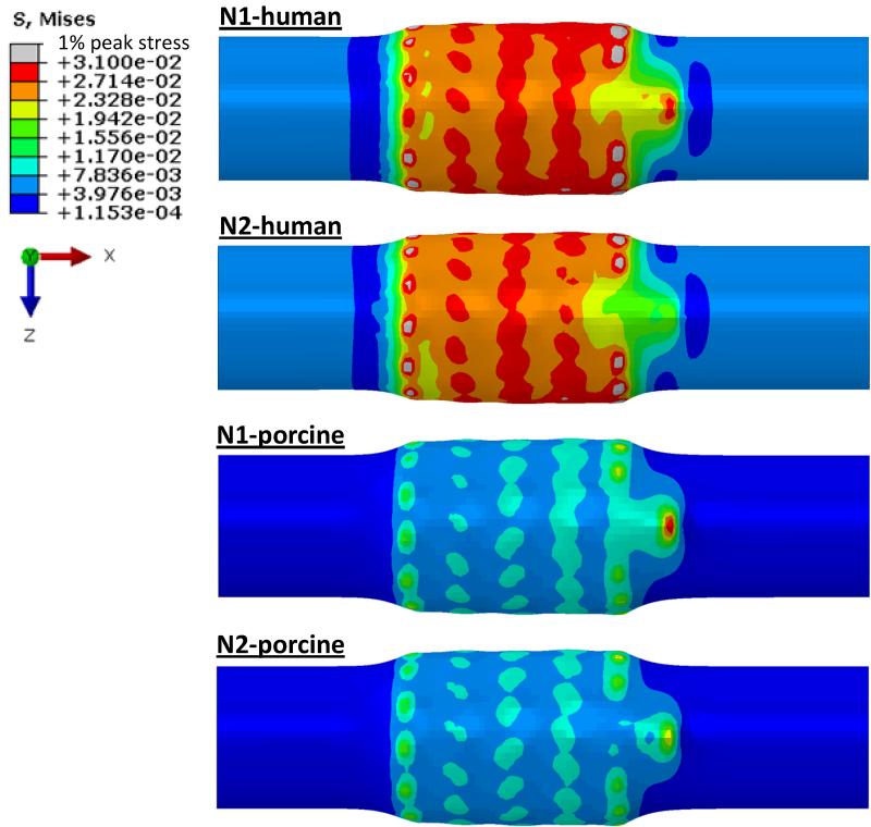
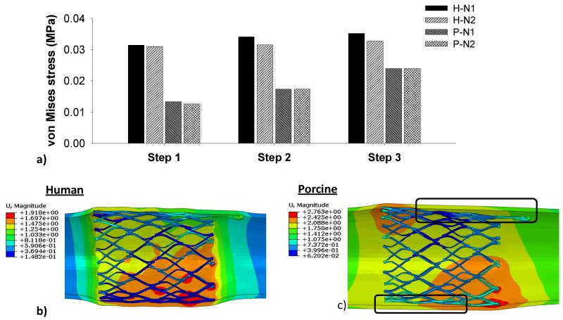
The von Mises stress distributions on the CS vessel wall in Step 1 are illustrated in Fig. 5. It can be seen that peak stresses were located on the regions of the CS wall that were in contact with the strut links of the stent. The N1 stent induced the highest peak stresses on the human model, whereas N2 stent had the lowest peak stresses on the porcine model. The 99-percentile peak stress in the human CS induced by N1 stent was about two-fold higher than that in the porcine tissue, i.e., 31.40 kPa in human vs. 13.36 kPa in porcine. The stresses induced by N2 stent were slightly lower than those of N1 stent for both human (30.97 kPa) and porcine (12.57 kPa) tissues. In steps 2 and 3, as shown in Fig. 6a, there was a slight increase of the stresses in both human and porcine CS walls. The application of the axial force at the connector end and the internal pressure could result in the loss of wall apposition at the proximal end of the stent. As illustrated in the Fig. 6c, the porcine model had a gap between the vessel wall and the stent, whereas a better stent apposition was achieved in the human vessel, as shown in Fig. 6b.
Figure 5.
Contour plots of von Mises stress distribution on the human and porcine coronary sinus walls after initial contact with Nitinol stents (N1 and N2).
Figure 6.
a) The 99-percentile peak von Mises stresses on human and porcine vessel walls imposed by N1 and N2 stents in the 3-step TSI simulation, b) the human-N1 interaction with a good stent apposition, and c) the porcine-N1 interaction where stent is separated from the vessel wall.
Stent strain
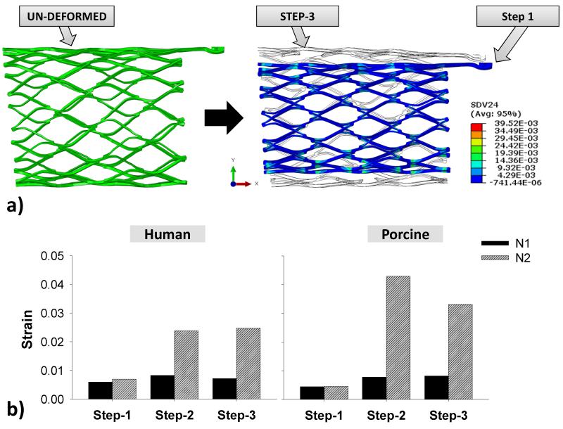
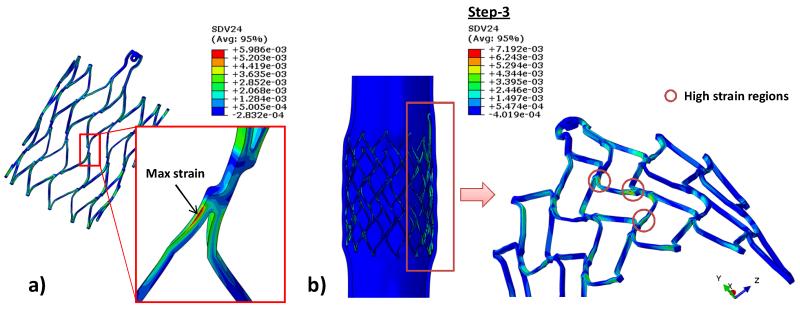
Fig. 7a illustrates the un-deformed and crimped stent shapes, as well as the shape after step 3 for the N1 stent. The stent deformed nearly back to its original configurations at the end of the step 3. As shown in Fig. 7b, the peak strains of stent N1 stent did not fluctuate much throughout the 3-step simulation in both human and porcine models whereas they increased significantly in the N2 stent after step 1. The maximum strain on the stent in Fig. 8a was found to be at twisted struts near strut links in all simulations. During steps 2 and 3, high strain regions were observed mostly at the strut link locations near the connector region (Fig. 8b).
Figure 7.
a) Visualization of the stent N1’s undeformed geometry prior to crimping (left) and of the shape and strain contour of the stent after crimping overlapping with the shape after the step-3 (right); b) the maximum tensile strains in each step of both stents in the human and porcine TSI simulations.
Figure 8.
a) Common maximum local strain observed on the stent strut in all steps (N1 stent is shown), and b) regions that are under high strain after applied a pressure to the inner vessel wall for stent N1.
Contact forces
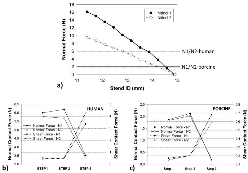
Maximum interactive radial forces of 16 N and 9.5 N were needed to crimp N1 and N2 stents from the ID of 14.90 mm to 11.98 mm, respectively, as shown in Fig. 9a. In Step 1, the maximum radial forces imposed by the stents on the human CS wall were about three times larger than those in the porcine model, i.e., 5.99 N versus 1.86 N. It can be seen that in Fig. 9b & c, the stent N1 generated slightly higher normal and shear forces than the stent N2 at the initial contact in step 1, i.e., 5.99 N and 0.50 N vs. 5.78 N and 0.44 N for human and 1.86 N and 0.17 N vs. 1.83 N and 0.15 N for porcine, respectively. Both normal and shear forces slightly increased when applied an axial force of 2.45 N. In step 3, when a pressure was exerted to the inner vessel wall, shear forces increased while normal forces dropped due to the tissue in-growth contact condition.
Figure 9.
a) The relation between stents’ inner diameter and radial force during crimping. Lines across the graph represented the maximum normal forces generated from stent N1 in human and porcine and dotted lines presented the N2 after step 1; the normal and shear forces in the 3-step TSI simulation for b) human and c) porcine in the 3-step TSI simulations.
Fatigue analysis of stents
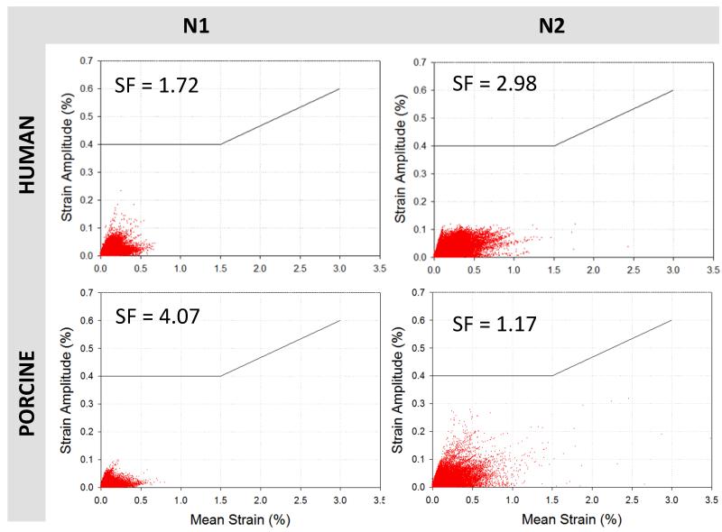
The Goodman diagrams in Fig. 10 plotted the fatigue-life responses of the two stents under a cyclic loading pressure of 0-10 mmHg. Although all strain values of the N2 stent in human and porcine tissues were below the constant life line curve of 0.4%, they were more scattered and wide-spread compared to the N1 stent. The maximum oscillating strain of the N1 stent in the human model was 0.23%, and its safety factor was 1.72. The safety factor of the N2 stent was higher, 2.98, with the oscillating strain of 0.13%. When deployed in porcine tissue, the N1 stent had a safety factor of 4.07. In contrast, a very high cyclic strain of 0.34% observed in the N2 stent resulted in a relatively low safety factor of 1.17.
Figure 10.
Goodman diagrams presenting the fatigue life of stents N1 and N2 after applied a 10 mmHg of pressure in the vessel walls, the black line represents the predicted fracture above 0.4 % strain amplitude for a range of mean strains.
DISCUSSION
Interaction forces and stent migration
In this study, we simulated and compared the biomechanical interactions between two anchoring stents and two CS vessels – the human and porcine CS vessels. Under the same loading and boundary conditions, the stents deployed into the stiffer human vessel underwent much higher interactive normal contact forces than when deployed into the porcine vessel. In addition, a larger gap between the porcine wall and the stents was observed, suggesting that the potential for stent migration is much higher in the porcine model than in the human model. This result underscored the importance of the CS tissue mechanical properties, and also brought up questions on the validity of using animal models to evaluate the device performance. We recently performed biaxial mechanical testing of CS tissues from three species: aged human (86.5 ± 9.7 years old), porcine (6 - 9 months old) and ovine (1 year old) tissues. It was also found that there were substantial mechanical property differences among these three species [27], with the aged human tissue being much stiffer than animal tissues. Older animals may provide stiffer tissue properties that are similar to aged humans, although this hypothesis has not been assessed.
In step 3, the contact definition between the CS wall and the stent was set as a non-slipping condition to imitate the effect of long-term tissue in-growth in-between the stent struts. This contact condition was designed mainly to study the long-term stent fatigue damage, during which tissue in-growth would occur. It should be also noted that the axial pull mechanism from the bridge elements of the PTMA device occurred gradually and would not be fully active until the imbedded suture dissolved completely over approximately 1 month. During this period of time, stent anchoring inside the vessel may be enhanced because of the tissue in-growth. In the immediate post-deployment period, the normal contact force would be the dominant force. Without the axial pull the chance of stent migration is low. Moreover, the PTMA procedure is a beating heart operation, any immediate migration of the device may be corrected immediately in the operation.
Additionally, to investigate the no tissue in-growth condition, we further investigated the normal and shear forces in step 3 by setting the coefficient of friction between the stent N1 and the human CS inner wall as 0.1. From the simulation results, no stent migration was observed in step 3. The normal force of 3.55 N was similar to the original (rough, non-slipping) model of 3.52 N. The shear force, though, was reduced to 0.34 N while the shear on the original model is 3.34 N, as one would expect.
Another factor that could impact the stent migration is the CS geometry. We assumed the CS vessel was a cylindrical tube at the anchoring location. The actual anatomic geometry of the CS vessel has a larger diameter at the ostium and becomes narrower towards the GCV vessel, which may help prevent the stent from migrating towards the GCV vessel. However, this effect was not investigated in this study.
Vessel wall stress
Stent migration and perforation of CS vessel wall are the two competing factors that require a delicate balance of the expansion force of the deployed stent. A higher interactive force will facilitate the stent anchoring but may also cause damage to the CS vessel wall. The maximum peak stresses on the CS wall were about 0.5 – 1 MPa for the human model and about 20 – 200 kPa in the porcine model. Currently, the published data on the ultimate tensile strengths (UTS) of human CS wall tissues are limited. One study reported the UTS of porcine CS vessel, which are in the range of 1.66 – 2.57 MPa [28].Thus, based on the simulated peak stresses and the reported UTS of porcine CS tissue, the perforation of porcine CS wall would not occur. Moreover, we noticed that the peak stresses were concentrated on a very small number of nodal points, which represented less than 0.06% of total nodal points of the CS wall and were mainly located at the regions of the proximal and distal ends of the stent. The high stress concentration might be due to the excessive bending of the elements as a result of geometrical changes from expanded tissue-stent contact region to the non-tissue-stent contact region. Thus, to avoid local stress concentrations, the 99-percentile peak stress was adopted for the comparison among the four models [23, 29].
Stent fatigue analysis
In this study, we investigated the stents made of two different Nitinol materials. We found that the interactive forces induced by the two stents were similar; however, the fatigue safety factors of the four models were quite different. The stent N1 had a lower safety factor when deployed in human than porcine, while stent N2 had a better safety factor in human than porcine model. This result suggested that the stent material properties could have an impact on stent durability, but not significantly on its interactive responses with the CS tissues. Thus, a greater impact on the biomechanical interactions may be achieved by changing the structural design of the stent. Computational and clinical studies [30, 31, 32] have shown that decreasing the stent strut thickness has favorable outcomes in terms of lower chronic vessel stresses and lower clinical restenosis rate, which may be a direction for further improving the stent design.
Clinical Relevance
Currently, there are several percutaneous devices utilizing a similar trans-coronary sinus concept to reduce the dilated mitral annulus. For instance, the CARILLON device (Cardiac Dimensions, Kirkland, Washington), which consists of distal and proximal anchors (Nitinol and titanium) and joined by a Nitinol ribbon connector, could reduce the dilated annulus by manually pulling the proximal anchor toward the CS ostium. Due to the difficulty in anchoring to the CS wall, a second generation device was developed with a twist at the distal anchor. The device was implanted in humans for up 6 months of follow-up [33]. A total of 30 out of 40 patients successfully received the device with an average of 23% MR reduction. However, three patients suffered from CS perforation and dissection. Another device, Viacor (Viacor, Wilmington, Massachusetts), consists of up to three rigid Nitinol rods. Various rod sizes and stiffness are used to achieve the desired MR reduction. The issues with this device were associated with fracture, migration and delivery failures due to the vast difference in CS structures and geometries [34, 35]. Patients not only have high variability in CS anatomical structures, the mechanical properties of CS also varied greatly, as shown previously by Pham and Sun [27].
The current adverse events are associated with vessel injury (e.g. perforation and dissection) and device malfunctions (e.g. migration and fractures), which possibly are the results of mechanical mismatch between the implanted devices and the CS tissues. For instance, the CARILLON anchors were formed by two wires twisted together. Hence, lack of a sufficient stent-tissue contact surface might result in high stress concentration leading to perforation of the CS wall, as well as high possibility of device slippage. Fractures of the VIACOR device might be due to its lack of flexibility and stress reduction (due to its rod structure) to accommodate the dynamic motion of the CS vessel wall. Clearly, rigorous engineering analysis is warranted for the investigation of these device malfunctions.
Limitations
There are several limitations in this study. First, the CS vein is a long vessel that courses along the atrioventricular groove with larger diameter at the proximal section and smaller at the distal end. It has an oval shape with the supero-inferior diameter exceeding the anteroposterior dimension in a ratio of 5 to 4 [36], and half of the CS vessel wall is partially embedded in the myocardium and the other half is free of attachment. In future study, we will acquire patient-specific imaging data from multi-detector CT scans to develop a more realistic human CS model with more realistic and accurate TSI analyses. Moreover, the surrounding myocardium and active contraction boundary conditions are not included in this study. Grewal et al. [37] showed that for ischemic mitral regurgitation, there is no significant difference between the annulus diameter during the peak systole and diastole phases. Thus, we assumed during cardiac cycles, the myocardium active contraction will not impose extra loads on the PTMA device. Our FE model did not include the anisotropic material properties of the tissue. We are currently developing a fiber-based structural constitutive model to rigorously characterize the material properties of the tissues. Furthermore, stent fatigue analysis was simplified to one cycle analysis and simple pressure loading condition. In future studies, a complete TSI system, which consists of a distal anchor connected to a bridge element, a patient-specific CS model, and a more realistic boundary/loading conditions incorporating surrounding mitral tissues will be investigated.
Conclusion
Due to the mechanical property difference, the tissue-stent interactive responses from human and porcine models are distinct. The vessel wall stresses and contact forces imposed by the stents were much higher in human than porcine models. However, the differences in vessel wall maximum stresses and contact forces induced by the two stent types were relatively small. The softer stent exhibited a better fatigue safety factor when deployed in human model, and the stiffer stent was safer in porcine model. In our future study, a complete TSI system, which consists of a distal anchor connected to a bridge element, a patient-specific CS model, and a more realistic boundary conditions will be investigated. Although the presented study utilized a simple cylindrical tube for the CS wall, we provided, to our knowledge, the first engineering quantitative analysis of the proximal PTMA stent-CS vessel interactions using human and porcine CS models, which may offer scientific insight into future development and optimization of PTMA devices.
ACKNOWLEDGMENTS
This work was supported in part by the American Heart Association SDG grant No. 0930319N and a NIH NRSA Individual pre-doctoral fellowship.
APPENDIX A
Element Selection
In this study, we used the C3D8I element that has 8-integration points with a 5×5 layers of elements cross the stent and CS walls (Fig. 2c). For most of the stent analyses, due to the bending-dominated loading nature of the stent, the maximum stresses/strains are usually detected at the stent surface. The incompatible mode eight-node brick element (C3D8I) is preferred for stent analysis because it provides a good estimation on peak stress and strain and does not suffer from the hourglassing phenomenon if the integration points are closer to the surface. Although the quality of the C3D8I element is far from the fully integrated brick element, of which the best results are usually obtained with quadratic elements, they are relatively low in computation cost. For the current analysis, the computation time takes about 14 hours with 50 CPUs running on Intel Xeon X5650 Westmere cores.
Mesh Sensitivity
A selection of different mesh sizes was used to perform a mesh sensitivity analysis on the interaction of the CS vessel and PTMA proximal stent. Both of the CS wall and stent meshes were refined, and the results are shown in Table A1. The small differences (results from the end of step-1) between the three meshes suggest that mesh density has low impact on the simulation results. For the CS model, the mesh 3 achieved the smallest high stress compare with meshes 1 and 2. Therefore, the finest mesh 3 was chosen for both CS and stent models in this study. Table A2 shows all the maximum (MAX) and 99% stress values in each TSI step for all four models.
Table A1.
Mesh sensitivity analysis.
| Variables (Step-1) | Mesh 1 | Mesh 2 | Mesh 3 |
|---|---|---|---|
| No. of element – CS vessel | 25,920 | 34,561 | 43,199 |
| von Mises Stress at 99% (Mpa) | 0.044 | 0.035 | 0.031 |
| von Mises Stress at 1% (Mpa) | 1.109 | 1.097 | 0.884 |
| No. of element – Stent | 68,532 | 91,375 | 114,219 |
| Strain (SDV24) | 5.39E-03 | 5.82E-03 | 5.99E-03 |
| Normal forces (N) | 6.514 | 6.071 | 5.993 |
| Shear forces (N) | 0.551 | 0.523 | 0.498 |
Table A2.
Maximum (MAX) and 99% peak stress of CS vessel wall.
| STEP 1 | STEP 2 | STEP 3 | ||||
|---|---|---|---|---|---|---|
| 99 %(MPa) | MAX (MPa) | 99 %(MPa) | MAX(MPa) | 99 %(MPa) | MAX(MPa) | |
| Nl-human | 0.031 | 0.884 | 0.034 | 1.345 | 0.035 | 1.268 |
| N2-human | 0.031 | 0.507 | 0.032 | 0.951 | 0.033 | 1.074 |
| Nl-porcine | 0.013 | 0.056 | 0.017 | 0.175 | 0.024 | 0.239 |
| N2-porcine | 0.013 | 0.039 | 0.017 | 0.076 | 0.024 | 0.118 |
REFERENCES
- [1].Jones EC, Devereux RB, Roman MJ, Liu JE, Fishman D, Lee ET, Welty TK, Fabsitz RR, Howard BV. Prevalence and correlates of mitral regurgitation in a population-based sample (the Strong Heart Study) The American Journal of Cardiology. 2001;87(3):298–304. doi: 10.1016/s0002-9149(00)01362-x. [DOI] [PubMed] [Google Scholar]
- [2].Hickey MS, Smith LR, Muhlbaier LH, Harrell FE, Jr., Reves JG, Hinohara T, Califf RM, Pryor DB, Rankin JS. Current prognosis of ischemic mitral regurgitation. Implications for future management. Circulation. 1988;78(3 Pt 2):I51–59. [PubMed] [Google Scholar]
- [3].Lamas GA, Mitchell GF, Flaker GC, Smith SC, Jr., Gersh BJ, Basta L, Moye L, Braunwald E, Pfeffer MA. Clinical significance of mitral regurgitation after acute myocardial infarction. Survival and Ventricular Enlargement Investigators. Circulation. 1997;96(3):827–833. doi: 10.1161/01.cir.96.3.827. [DOI] [PubMed] [Google Scholar]
- [4].Di Donato M, Frigiola A, Menicanti L, Boghdabi A, Badia T, Neagu A, Montericcio V, Ranucci M. Moderate ischemic mitral regurgitation and coronary artery bypass surgery: effect of mitral repair on clinical outcome. J Heart Valve Dis. 2003;12(3):272–279. [PubMed] [Google Scholar]
- [5].Gillinov AM, Wierup PN, Blackstone EH, Bishay ES, Cosgrove DM, White J, Lytle BW, McCarthy PM. Is repair preferable to replacement for ischemic mitral regurgitation? J Thorac Cardiovasc Surg. 2001;122(6):1125–1141. doi: 10.1067/mtc.2001.116557. [DOI] [PubMed] [Google Scholar]
- [6].Grossi EA, Goldberg JD, LaPietra A, Ye X, Zakow P, Sussman M, Delianides J, Culliford AT, Esposito RA, Ribakove GH, Galloway AC, Colvin SB. Ischemic mitral valve reconstruction and replacement: comparison of long-term survival and complications. J Thorac Cardiovasc Surg. 2001;122(6):1107–1124. doi: 10.1067/mtc.2001.116945. [DOI] [PubMed] [Google Scholar]
- [7].Condado JA, Velez-Gimon M. Catheter-based approach to mitral regurgitation. J Interv Cardiol. 2003;16(6):523–534. doi: 10.1046/j.1540-8183.2003.01052.x. [DOI] [PubMed] [Google Scholar]
- [8].Kaye DM, Byrne M, Alferness C, Power J. Feasibility and short-term efficacy of percutaneous mitral annular reduction for the therapy of heart failure-induced mitral regurgitation. Circulation. 2003;108(15):1795–1797. doi: 10.1161/01.CIR.0000096051.23734.28. Epub 2003 Oct 1796. [DOI] [PubMed] [Google Scholar]
- [9].Maniu CV, Patel JB, Reuter DG, Meyer DM, Edwards WD, Rihal CS, Redfield MM. Acute and chronic reduction of functional mitral regurgitation in experimental heart failure by percutaneous mitral annuloplasty. J Am Coll Cardiol. 2004;44(8):1652–1661. doi: 10.1016/j.jacc.2004.03.085. [DOI] [PubMed] [Google Scholar]
- [10].Siminiak T, Hoppe UC, Schofer J, Haude M, Herrman JP, Vainer J, Firek L, Reuter DG, Goldberg SL, Bibber RV. Effectiveness and Safety of Percutaneous Coronary Sinus-Based Mitral Valve Repair in Patients With Dilated Cardiomyopathy (from the AMADEUS Trial) Am J Cardiology. 2009;104:565–570. doi: 10.1016/j.amjcard.2009.04.021. [DOI] [PubMed] [Google Scholar]
- [11].Hoppe UC, Brandt MC, Degen H, Dodos F, Schneider T, Stoepel C, Kroener A, Haude M. Percutaneous Mitral Annuloplasty Device Leaves Free Access to Cardiac Veins for Resynchronization Therapy. Catheterization and Cardiovascular Interventions. 2009:74. doi: 10.1002/ccd.22097. [DOI] [PubMed] [Google Scholar]
- [12].Siminiak T, Firek L, Jerzykowska O, Katmucki P, Wotoszyn M, Smuszkiewicz P, Link R. Percutaneous valve repair for mitral regurgitation using the Carillon(TM)-Mitral Contour System(TM). Description of the method and case report. Kardiologia Polska. 2007;65(3):272–278. [PubMed] [Google Scholar]
- [13].Webb JG, Harnek J, Munt BI, Kimblad PO, Chandavimol M, Thompson CR, Mayo JR, Solem JO. Percutaneous transvenous mitral annuloplasty: initial human experience with device implantation in the coronary sinus. Circulation. 2006;113(6):851–855. doi: 10.1161/CIRCULATIONAHA.105.591602. Epub 2006 Feb 2006. [DOI] [PubMed] [Google Scholar]
- [14].Duffy SJ, Federman J, Farrington C, Reuter DG, Richardson M, Kaye DM. Feasibility and short-term efficacy of percutaneous mitral annular reduction for the therapy of functional mitral regurgitation in patients with heart failure. Catheter Cardiovasc Interv. 2006;68(2):205–210. doi: 10.1002/ccd.20810. [DOI] [PubMed] [Google Scholar]
- [15].Harnek J, Webb JG, Kuck KH, Tschope C, Vahanian A, Buller CE, James SK, Tiefenbacher CP, Stone GW. Transcatheter implantation of the MONARC coronary sinus device for mitral regurgitation. JACC: Cardiovascular Interventions. 2011;4(1):115–122. doi: 10.1016/j.jcin.2010.08.027. [DOI] [PubMed] [Google Scholar]
- [16].El-Maasarany S, Ferrett CG, Firth A, Sheppard M, Henein MY. The coronary sinus conduit function: Anatomical study (relationship to adjacent structures) Europace. 2005;7:475–481. doi: 10.1016/j.eupc.2005.05.013. [DOI] [PubMed] [Google Scholar]
- [17].Pham T, Sun W. Comparison of biaxial mechanical properties of coronary sinus tissues from porcine, ovine and aged human species. Journal of the Mechanical Behavior of Biomedical Materials. 2012;6:21–29. doi: 10.1016/j.jmbbm.2011.09.001. [DOI] [PMC free article] [PubMed] [Google Scholar]
- [18].Kleinstreuer C, Li Z, Basciano C, Seelecke S, Farber M. Computational mechanics of Nitinol stent grafts. J Biomech. 2008;41(11):2370–2378. doi: 10.1016/j.jbiomech.2008.05.032. [DOI] [PubMed] [Google Scholar]
- [19].Pham T, Sun W. Characterization of the mechanical properties of the coronary sinus for percutaneous transvenous mitral annuloplasty. Acta Biomaterialia. 2010;6(11):4336–4344. doi: 10.1016/j.actbio.2010.05.028. [DOI] [PMC free article] [PubMed] [Google Scholar]
- [20].Ogden RW. Non-linear elastic deformations. Dover, Toronto: 1997. [Google Scholar]
- [21].DeHerrera MA, Sun W. Numerical Study of Metal Fatigue in a Superelastic Anchoring Stent Embedded in Coronary Sinus; Simulia Customer Conference Proceedings London; England. 2009.pp. 713–726. [Google Scholar]
- [22].Auricchio F, Conti M, De Beule M, De Santis G, Verhegghe B. Carotid artery stenting simulation: From patient-specific images to finite element analysis. Medical Engineering and Physics. 2011;33(3):281–289. doi: 10.1016/j.medengphy.2010.10.011. [DOI] [PubMed] [Google Scholar]
- [23].Speelman L, Bosboom EMH, Schurink GWH, Hellenthal FAMVI, Buth J, Breeuwer M, Jacobs MJ, van de Vosse FN. Patient-Specific AAA Wall Stress Analysis: 99-Percentile Versus Peak Stress. European Journal of Vascular and Endovascular Surgery. 2008;36(6):668–676. doi: 10.1016/j.ejvs.2008.09.007. [DOI] [PubMed] [Google Scholar]
- [24].FDA . In: Guidance for Industry and FDA Staff: Non-Clinical Engineering Tests and Recommended Labeling for Intravascular Stents and Associated Delivery Systems. U. S. D. o. H. a. H. Services, editor. U.S. Department of Health and Human Services; Rockville, MD: 2010. [Google Scholar]
- [25].Cavanaugh KJ, Jr., Holt V, Goode J, Anderson E. FDA Recommendations for Nitinol Stent and Endovascular Graft Fatigue Characterization and Fracture Reporting. Journal of ASTM International. 2006;3(6):8–18. [Google Scholar]
- [26].Pelton AR, Schroeder V, Mitchell MR, Gong XY, Barney M, Robertson SW. Fatigue and durability of Nitinol stents. Journal of the Mechanical Behavior of Biomedical Materials. 2008;1(2):153–164. doi: 10.1016/j.jmbbm.2007.08.001. [DOI] [PubMed] [Google Scholar]
- [27].Pham T, Sun W. Comparison of biaxial mechanical properties of coronary sinus tissues from porcine, ovine and aged human species. Journal of the Mechanical Behavior of Biomedical Materials. 2011 doi: 10.1016/j.jmbbm.2011.09.001. In press. [DOI] [PMC free article] [PubMed] [Google Scholar]
- [28].Balazs T, Bognar E, Zima E, Dobranszky J. Mechanical properties of coronary veins. GepeszetBudapest; Hungary: 2008. [Google Scholar]
- [29].Heng MS, Fagan MJ, Collier JW, Desai G, McCollum PT, Chetter IC. Peak wall stress measurement in elective and acute abdominal aortic aneurysms. Journal of Vascular Surgery. 2008;47(1):17–22. doi: 10.1016/j.jvs.2007.09.002. [DOI] [PubMed] [Google Scholar]
- [30].Zahedmanesh H, Lally C. Determination of the influence of stent strut thickness using the finite element method: Implications for vascular injury and in-stent restenosis. Medical and Biological Engineering and Computing. 2009;47(4):385–393. doi: 10.1007/s11517-009-0432-5. [DOI] [PubMed] [Google Scholar]
- [31].Pache J, Kastrati A, Mehilli J, Schühlen H, Dotzer F, Hausleiter J, Fleckenstein M, Neuman FJ, Sattelberger U, Schmitt C, Müller M, Dirschinger J, Schömig A. Intracoronary stenting and angiographic results: Strut thickness effect on restenosis outcome (ISAR-STEREO-2) trial. Journal of the American College of Cardiology. 2003;41(8):1283–1288. doi: 10.1016/s0735-1097(03)00119-0. [DOI] [PubMed] [Google Scholar]
- [32].Kastrati A, Mehilli J, Dirschinger J, Dotzer F, Schühlen H, Neumann FJ, Fleckenstein M, Pfafferott C, Seyfarth M, Schömig A. Intracoronary stenting and angiographic results: Strut thickness effect on restenosis outcome (ISAR-STEREO) trial. Circulation. 2001;103(23):2816–2821. doi: 10.1161/01.cir.103.23.2816. [DOI] [PubMed] [Google Scholar]
- [33].Schofer J, Siminiak T, Haude M, Herrman JP, Vainer J, Wu JC, Levy WC, Mauri L, Feldman T, Kwong RY, Kaye DM, Duffy SJ, Tübler T, Degen H, Brandt MC, Van Bibber R, Goldberg S, Reuter DG, Hoppe UC. Percutaneous mitral annuloplasty for functional mitral regurgitation: Results of the CARILLON mitral annuloplasty device european union study. Circulation. 2009;120(4):326–333. doi: 10.1161/CIRCULATIONAHA.109.849885. [DOI] [PMC free article] [PubMed] [Google Scholar]
- [34].Sack S. e. a. Percutaneous Transvenous Mitral Annuloplasty: Initial Human Experience With a Novel Coronary Sinus Implant Device. Circ Cardiovasc Interv. 2009;2:277–284. doi: 10.1161/CIRCINTERVENTIONS.109.855205. [DOI] [PubMed] [Google Scholar]
- [35].Dubreuil O, Basmadjian A, Ducharme A, Thibault B, Crepeau J, Lam JY, Bilodeau L. Percutaneous mitral valve annuloplasty for ischemic mitral regurgitation: first in man experience with a temporary implant. Catheter Cardiovasc Interv. 2007;69(7):1053–1061. doi: 10.1002/ccd.21186. [DOI] [PubMed] [Google Scholar]
- [36].Loukas M, Bilinsky S, Bilinsky E, El-Sedfy A, Anderson RH. Cardiac Veins: A Review of the Literature. Clinical Anatomy. 2009;22:129–145. doi: 10.1002/ca.20745. [DOI] [PubMed] [Google Scholar]
- [37].Grewal J, Suri R, Mankad S, Tanaka A, Mahoney DW, Schaff HV, Miller FA, Enriquez-Sarano M. Mitral Annular Dynamics in Myxomatous Valve Disease: New Insights with Real-Time 3-Dimensional Echocardiography. Circulation. 2010;121(12):1423–1431. doi: 10.1161/CIRCULATIONAHA.109.901181. [DOI] [PubMed] [Google Scholar]


