Abstract
Background
One of the greatest challenges in scaffold based tissue engineering remains poor and inefficient penetration of cells into scaffolds to generate thick vascularized and cellular tissues. Electrospinning has emerged as a preferred method for producing scaffolds with high surface area to volume ratios and resemblance to extracellular matrix. However, cellular infiltration and vascular ingrowth is insufficient due to lack of macro-pore interconnectivity in electrospun scaffolds with high fiber density. In this study we report a novel two-step electrospinning and laser cutting fabrication method to enhance the macro-porosity of electrospun scaffolds.
Materials and Methods
Polycaprolactone dissolved in hexafluoroisopropanol was electrospun at 25kV to create uniform 100–120 µm sheets of polycaprolactone fiber mats (1–5 µm fiber diameter) with an array of pores created using VERSA LASER CUTTER 2.3. Three groups of fiber mats with three distinct pore diameters (300µm, 160µm and 80µm, all with 15% pore area) were fabricated and compared to a control group without laser cut pores. After laser cutting, all mats were collagen coated and manually wrapped around a catheter six times to form six concentric layers prior to implantation into the omentum of Lewis rats. Cellular infiltration and vascular ingrowth were examined after 2 weeks.
Results
Histological analysis of 14 day samples showed that scaffolds with laser cut pores had close to 40% more cellular infiltration and increased vascular ingrowth in the innermost layers of the construct as compared to the control group. Despite keeping pore area percentage constant between the three groups, the sheets with largest pore size performed better than those with smaller pore sizes.
Conclusions
Porosity is the primary factor limiting the extensive use of electrospun scaffolds in tissue engineering. Our method of LASER cutting pores in electrospun fibrous scaffolds ensures uniform pore sizes, easily controllable and customizable pores, and enhances cellular infiltration and vascular ingrowth demonstrating significant advancement towards utility of electrospun scaffolds in tissue engineering.
Introduction
Electrospinning has emerged as a well-accepted method for fabricating scaffolds for various applications in tissue-engineering. Electrospun fibrous mats are characterized by fiber diameters ranging from 10 nm to 10 µm [1][2][3] resulting in high surface area per unit volume that is desirable for cellular adhesion. These non-woven fibrous mats have a structural morphology similar to the native extracellular matrix. Due to the random deposition of particularly thin fibers into a densely packed mesh, electrospinning results in scaffolds that have exceedingly fine pore structures. As a result, even though these scaffolds have high porosity, their individual pore diameters are very small, limiting easy infiltration of cells into the scaffolds and development of vascularized scaffolds necessary to sustain thick tissues.
Eichhorn et al. have shown that there is a direct correlation between the mean pore radii of electrospun matrices and their fiber diameters. Larger fiber diameters result in larger pore sizes and vice versa. As an example, fiber diameters of 200 nm would result in pore radii of only around 20 nm, which is not sufficient for cellular penetration. It is possible to control the pore sizes by controlling the average fiber diameters via various electrospinning parameters such as viscosity of the solution, speed of rotation of the collecting mandrel, applied voltage and distance between the mandrel and the syringe. Another group has suggested fabricating electrospun scaffolds with both synthetic and natural polymers. Although they successfully showed enhanced cellular adhesion, the cellular infiltration was restricted [4].
Others suggested the use of porogens to increase the pore sizes in the fiber mats. Among these, Zhang et al. were the first to electrospin a blended solution of polycaprolactone (PCL) with gelatin without crosslinking the two. Gelatin was later removed by immersing the scaffolds in aqueous media to leave behind voids that resulted in porous scaffolds [5]. Baker et al. used water-soluble polyethylene oxide (PEO) as the sacrificial polymer and co-spun it with PCL [6]. Nam et al. also tried similar experiments by trapping salt crystals between PCL fibers. Another study by Wright et al. tried incorporating salt crystals by dropping them on the rotating mandrel during electrospinning of poly (L-lactide) polymer. After leaching out the salt crystals using water, the scaffolds had reduced elastic modulus and yield strain. These studies showed that the overall pore sizes in the scaffolds and thereby the cellular infiltration, increased with increase in the amount of porogens. However, this also compromised structural integrity of the scaffolds [7]. Leong et al. suggested cryo-electrospinning where the electrospinning mandrel was maintained at extremely low temperatures and controlled humidity, resulting in deposition of ice crystals that were subsequently removed by lyophilization leaving behind macro-porous structure of the scaffold [8]. A recently published method to increase the cellular infiltration suggests the use of air-impedance electrospinning using a modified hollow electrospinning mandrel with well-defined pores on the surface. Highly pressurized air expelled from these pores disrupts the fiber deposition [9]. Vaquette et al. recently suggested the use of patterned collectors to increase the pore size of electrospun scaffolds for enhanced cellular infiltration. They showed that electrospun fibrous mats accurately mimicked the collector patterns. A 10-fold increase in pore sizes in regions of lower fiber density was achievable by this method, resulting in fibroblast migration of up to 250 µm into the scaffold [10]. However, most of these approaches are limited by the reduced structural integrity of the scaffolds as well as irregular and non-homogenous pores.
Our method involves the use of a highly accurate CO2 laser cutter to produce uniformly sized and evenly spaced pores on electrospun PCL fiber mats without disturbing the fiber structure to significantly increase cellular infiltration and vascular ingrowth into multi-layer scaffolds. This technique would be useful for the engineering of any tissues thicker than 250 µm, such as the intestinal smooth muscle. We employed three groups of scaffolds with three distint pore diameters (300 µm, 160 µm and 80 µm, all with 15% overall pore area) and compared them with control scaffolds without laser cut pores. These fiber mats were coated with collagen and wrapped around a catheter into six concentric layers to obtain cylindrical constructs with a radius of 2.5 mm (1.5 mm catheter and 1 mm of PCL sheets). They were then implanted into the omentum of Lewis rats. Cellular infiltration and vascular ingrowth were examined at 2 weeks.
Materials and Methods
Materials
PCL was obtained from Durect Corporation (Pelham, Alabama). Hexafluoro-2-propanol (HFIP) used to dissolve PCL was obtained from Sigma-Aldrich Corp (St. Louis, Missouri) and Purecol from Advanced BioMatrix (San Diego, California).
Methods
Electrospinning
11% (w/w) solution of PCL was made in HFIP. The solution was kept on a shaker for one hour to obtain a homogenous polymer solution. The mandrel was carefully wrapped with aluminum foil to ease the removal of the scaffold. The polymer solution was then electrospun on the mandrel at the following settings: polymer infusion rate of 2.5 mL/hr, mandrel rotational speed of 3450 rpm, applied voltage of 25 kV, and distance between mandrel and needle at 15 cm. After 0.5 mL of polymer solution was dispensed from the syringe onto the rotating mandrel, the mandrel was carefully removed and dipped in nanopure water for 2 minutes to easily slide the scaffold out. Scaffolds were air dried overnight before laser cutting.
Pore formation using the LASER cutter
The electrospun PCL scaffolds were obtained as fiber mats with 10 × 2.5 cm dimensions based on the mandrel used. These fiber mats were cut into narrower strips of 7×1 cm dimentions using sterilized surgical scissors. Once scaffolds with appropriate dimensions were obtained, pores were cut using the VERSA LASER cutter 2.3 (Scottsdale, AZ). These macro-pores were patterned to achieve slight overlapping as the scaffold layers were rolled around the catheter. A speed of 98%, power of 10% and pulses per inch of 150 were used on the CO2 laser cutter to obtain the desired results. Pores with diameters of 300 µm, 160 µm and 80 µm were cut, all with 15% pore area.
Fabrication of the rolled scaffold construct
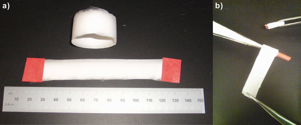
Fiber mats with laser cut pores and those without laser cut pores were plasma etched using the Harrick Plasma Cleaner/Sterilizer PDC-32G. These plasma etched sterile scaffolds were then coated with collagen using sterile techniques by dropping 75 µL of 0.05% neutralized collagen per cm2 of the scaffold sheet, to enhance cellular attachment. The collagen coated electrospun mats were then rolled around a 10 French urological catheter obtained from C.R.Bard (Convington, Georgia) into six concentric layers, the ends of which were then sutured to hold the six layers together. The two ends were sealed with a silicone plug to form a close-ended cylindrical construct and promote cellular infiltration only through the curved surface of the scaffold and not from the ends of the construct (Fig. I)
Figure I.
Bright field images (keyence microscope) of electrospun PCL scaffolds. a) Electrospun PCL scaffold fiber mat, b) Cut PCL fiber mat being wrapped around the catheter.
Scaffold implantation
Lewis rats weighing 250–300 g were obtained from Charles River Laboratories (Wilmington, Massachusetts). Rats were anesthetized with isoflurane and then injected with 0.3 mL of 0.01 mg/mL buprenorphine.
A small region of the abdomen was shaved and disinfected by wiping with betadine and alcohol. An incision was made through the skin and the underlying muscle layer to gently pull out a small piece of the omentum. The omentum was carefully wrapped around the rolled scaffold construct and loosely sutured with a 3-0 silk suture obtained from Ethicon (Somerville, New Jersey). The omentum-wrapped construct was returned into the peritoneal cavity. The muscle layer and skin were closed with 3-0 silk suture and 3-0 nylon suture, respectively. Scaffolds with 300 µm (n=6), 160 µm (n=4) and 80 µm (n=4) pore diameters were implanted, with just one scaffold per animal. Electrospun PCL fiber mats without pores (n=4) were used as controls. The animals were maintained and handled in compliance with the institutional regulations established and approved by the Animal Research Committee at the University of California, Los Angeles. Rats were sacrificed after two weeks by exposing them to an overdose of isoflurane. Rolled scaffold constructs were then removed, and excess tissue was gently teased away. Extracted scaffold was fixed in formalin for 24 hours. Sutures on both ends of the catheter were cut open to remove the catheter. The concentrically rolled scaffold layers remained stuck to each other, even after the removal of the sutures, owing to cellular infiltration into the scaffold as well as the formalin fixation process. Sections of the rolled scaffold were then paraffin embedded for further analysis.
Histological processing
Ten 5-µm cross-sections were cut from paraffin blocks and were chosen at random to be immunostained with 1:50 mouse anti-α SMA antibody obtained from Dako (Carpinteria, California), and visualized with 1:200 fluorescein-conjugated goat anti-mouse secondary antibodies (Invitrogen, Carlsbad, California) and the nuclear stain 4,6-diamidino-2-phenyl-indole dihydrochloride (DAPI). Briefly, slides were de-waxed in xylene twice for 5 minutes each, then serially rehydrated in 100%, 95% and 70% ethanol solutions followed by deionized water. The rehydrated slides were then placed in Citra antigen retrieval solution at 95°C for 15 minutes followed by a 5 minutes wash in 0.5% Triton-X in Tris Buffer Solution (TBS). After two washes with PBS-Tween 20, 5% normal goat serum in 2% BSA/PBS-T (2% Bovine serum albumin in phosphate buffered saline-Tween) solution was added to each of the samples on the slides; followed by a one-hour incubation at room temperature. α-Smooth muscle actin primary antibody solution (1:50 Dilution) was then added to all the samples, and the slides were left for overnight incubation at 4°C. After incubation, fluorescent secondary antibody and Vectashield mounting medium with nuclear stain DAPI obtained from Vector Laboratories (Burlingame, California) was added to the samples. Samples were examined under the Carl Zeiss MicroImaging, LLC, microscope (Thornwood, New York). To visualize the extracellular matrix deposition, 5-µm sections were stained with Trichrome.
Quantification of cellular infiltration and vascular ingrowth
Cellular infiltration was quantified by counting the number of DAPI stained nuclei at 40X magnification in each layer of the scaffold around the catheter. Counting was done in five sections in each layer, and the numbers were averaged to get the final cell count for each layer. Ingrowth of blood vessels through the individual layers was quantified manually using Image Scope software (Aperio Technologies, Vista, CA) by counting the number of smooth muscle actin stained vessels in each layer throughout the circumference of the scaffold.
Mechanical testing of CO2 laser cut scaffolds
The PCL fiber mats were tested under tension using an universal testing machine (Instron 5564 Tester, Norwood, MA) following protocols outlined in Chung et al [11]. Briefly, individual scaffolds were cut with either no pores or with 300 µm, 160 µm and 80 µm pores in a 14 mm by 17 mm pattern on opposite sides of the cylinder. After cutting these pores, all fiber mats were cut to identical dimensions of 14-mm wide and 50-mm long using surgical scissors. These mats were stretched between parallel cross-bars at a rate of 10 mm/min while load and displacement were recorded to calculate maximum force and Young’s modulus.
Statistical Method
Statistically significant differences were determined using a one-way repeated measures analysis of variance (ANOVA). The criterion level for determination of statistical significance was set at P < 0.05 for all computations (unless mentioned).
Results
Scaffold fabrication and characterization
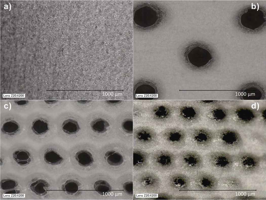
11% PCL polymer solutions electrospun for 10 minutes yielded fiber mats with thickness of 100–120 µm, determined by cryosectioning the scaffolds and measuring their thickness under a microscope. The image of the electrospun fiber mat without pores was obtained using a Keyence microscope, which revealed fibers with diameters in the range of 1–5 µm (Fig. IIa). Three pore diameters (300, 160 and 80 µm) were selected (Fig. IIb, IIc, IId). Pore diameters below 80 µm were not attempted due to limitations of the CO2 laser cutter. High-energy carbon dioxide laser resulted in slight melting of electrospun fibers around the pores, however fibers away from the pores were unaffected.
Figure II.
Bright field images (keyence microscope) of electrospun PCL scaffolds. a) Scaffold without pores, b) Scaffold with 300 µm pores, c) Scaffold with 160 µm pores and d) Scaffold with 80 µm pores.
Cellular infiltration
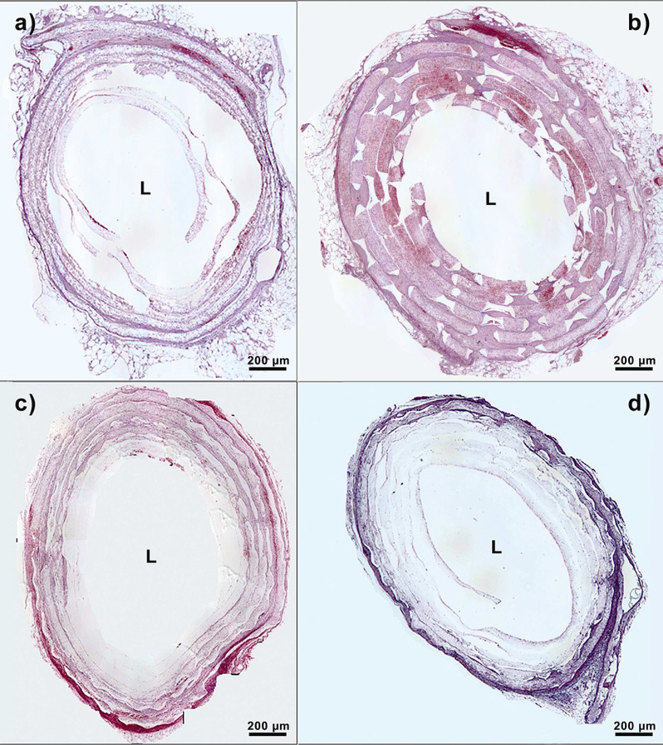
The fiber mats with or without laser cut pores were rolled around the catheter into six concentric layers. After 2 weeks of implantation, rolled scaffolds were retrieved from the peritoneal cavity. Rolled scaffolds without laser cut pores showed cellular infiltration only through the outermost two layers, thus spanning a distance of around 350 µm (Fig. IIIa). In addition, upon processing these samples for histology, the lack of deposited extracellular matrix due to lesser cellular penetration led to the loss of an organized, six-layered structure.
Figure III.
Hitological sections of implanted PCL scaffolds at day 14. ’L’ represents the Lumen. a) Scaffold without pores, b) Scaffold with 300 µm pores, c) Scaffold with 160 µm pores and d) Scaffold with 80 µm pores.
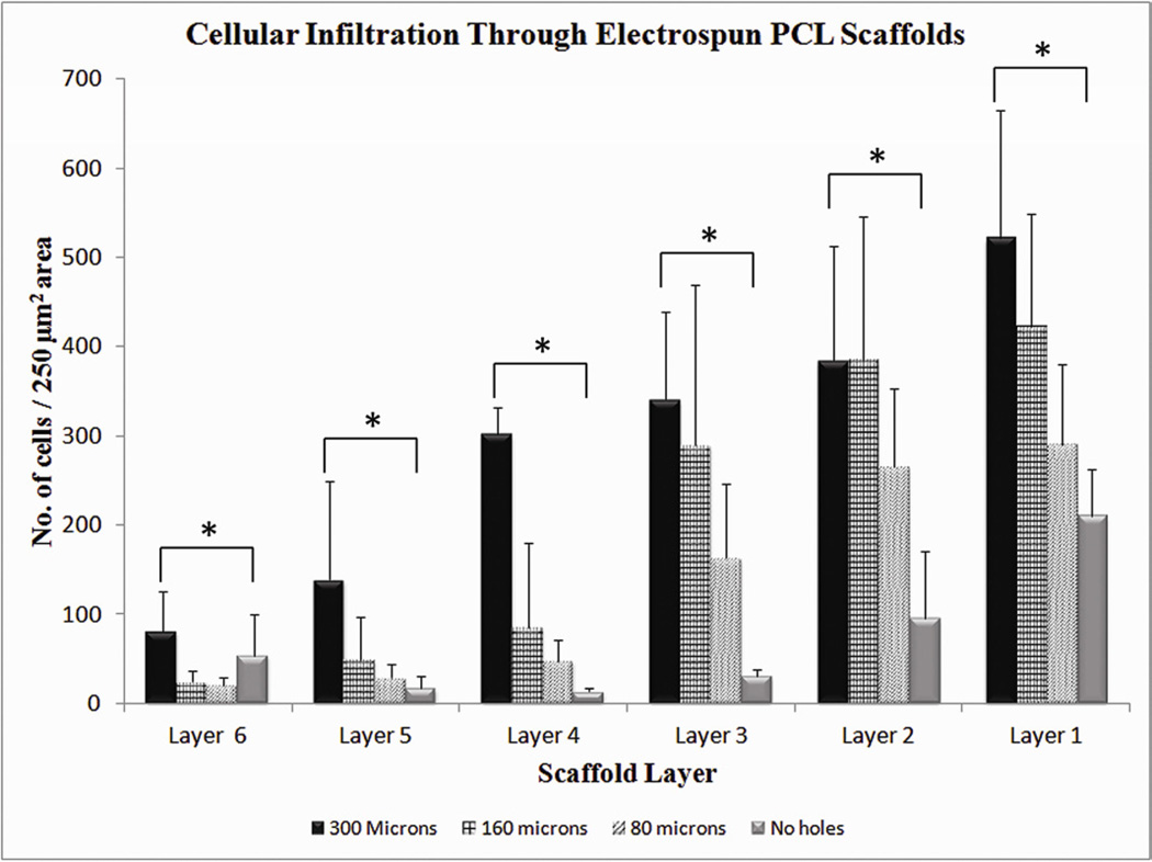
In contrast, rolled scaffolds with laser cut pores had significantly higher cellular infiltration, that increased with increasing pore diameter. Rolled scaffolds with 300-µm pores showed cellular infiltration to the innermost layer, with the greatest number of cells in each layer as compared to the other scaffolds (Fig. IIIb). Cells infiltrated through a distance of 1000 µm across the six layers in these scaffolds. Rolled scaffolds with 160-µm pores had cellular infiltration up to a depth of 600 µm (Fig. IIIc), whereas those with 80-µm pores had similar cellular infiltration depth as scaffolds without laser cut pores (Fig. IIId). The number of cells penetrating through each layer was also higher for rolled scaffolds with laser cut pores. Despite keeping the overall pore area percentage constant among the three groups, the sheets with largest pore diameter had 40% more cellular infiltration than the sheets without pores, in the innermost layers of the construct. Constructs with 300-µm pores were significantly different from constructs with 160-µm pores and 80-µm pores in the innermost three layers (Figure IV). Constructs with 300-µm pores were significantly different from constructs with no macropores in all layers except for the innermost layer. The innermost layer in the construct with no macropores had a small increased cellular infiltration, possibly due to migration of host cells from the ends that were incompletely sealed.
Figure IV.
Quantification of cellular infiltration as a function of scaffold layers at day 14. Values represent the mean and standard deviation. Layer 1 represents the outermost layer while layer 6 represents the innermost layer. Cellular infiltration through electrospun PCL scaffolds with 300 µm pore diameter (n=6), 160 µm pore diameter (n=4), 80 µm pore diameter (n=4) and Control without pores (n=4). * represents p<0.05
Blood vessel penetration
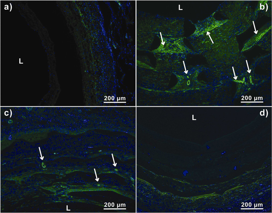
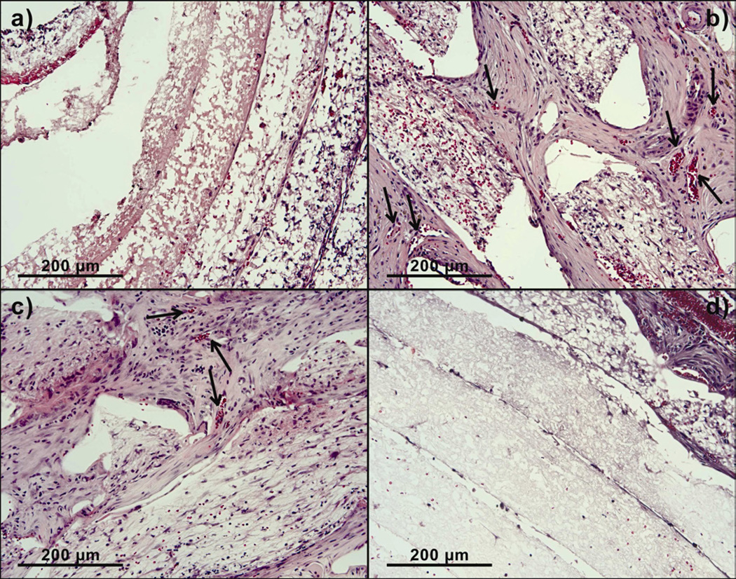
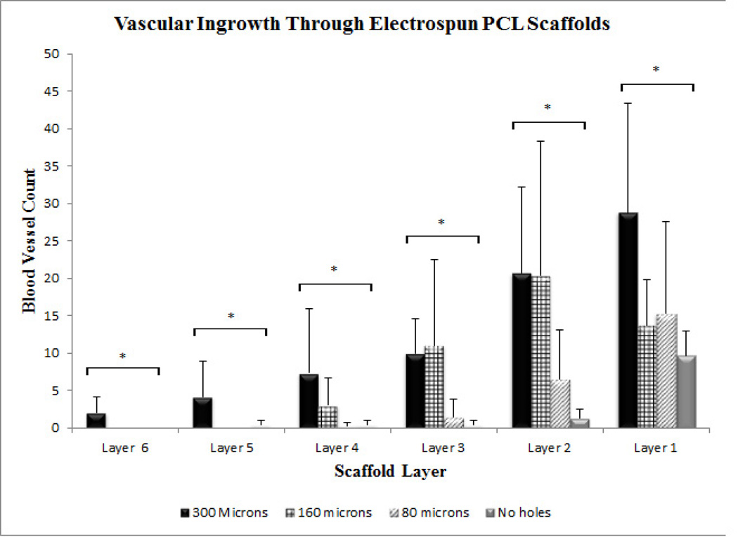
The vascular ingrowth into the rolled scaffolds was quantified by counting vessels stained by anti-α-smooth muscle actin antibody in each layer of the scaffold (Fig. V). Rolled scaffolds without pores stained weakly positive for α-smooth muscle actin, indicating negligible vascular ingrowth and smooth muscle actin positive cells. Rolled scaffolds with 300-µm pores showed the highest density of perfusable blood vessels as indicated by the presence of red blood cells inside vessels (Fig. VI). Vascular ingrowth in rolled scaffolds with 300 µm, 160 µm and 80 µm pores was seen up to a depth of 850 µm, 480 µm and 300 µm, respectively. Vascular ingrowth in constructs with 300-µm pores was significantly different from constructs with 80-µm pores and constructs without laser cut pores in all layers (Fig. VII). Significantly greater vascular ingrowth was seen in constructs with 300-µm pores as compared to constructs without laser cut pores and constructs with 80-µm pores. Constructs with 300-µm pores were significantly different from constructs with 160-µm pores only in the two innermost layers. The vascular ingrowth through layer 1, 2, 3 and 4 was similar in constructs with 300-µm pores and 160-µm pores (Fig. VII).
Figure V.
Anti-α SMA stained sections of harvested PCL scaffolds at day 14. Arrows represent matured blood vessels. ‘L’ represents the Lumen. a) Scaffold without laser cut pores, b) Scaffold with 300 µm laser cut pores, c) Scaffold with 160 µm laser cut pores and d) Scaffold with 80 µm laser cut pores.
Figure VI.
Higher magnification images of implanted PCL scaffolds treated with hematoxylin and eosin showing blood cells within blood vessels at day 14. a) Scaffold without pores, b) Scaffold with 300 µm pores, c) Scaffold with 160 µm pores and d) Scaffold with 80 µm pores.
Figure VII.
Quantification of vascular ingrowth as a function of scaffold layers at day 14. Values represent the mean and standard deviation. Layer 1 represents the outermost layer while layer 6 represents the innermost layer. Vascular ingrowth through electrospun PCL scaffolds with 300 µm pore diameter (n=6), 160 µm pore diameter (n=4), 80 µm pore diameter (n=4) and Control without pores (n=4). * represents p<0.05
Extracellular matrix deposition
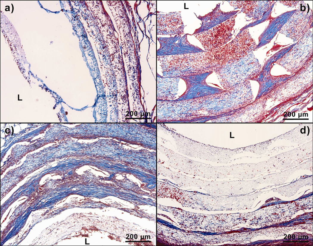
Significant swelling of the layers was seen with tremendous increase in cellular infiltration. The cross sections of the rolled scaffolds were stained with Trichrome to visualize the extracellular matrix deposition (Fig. VIII). Rolled scaffolds with 300 µm pores showed an increase in thickness of each layer, from the initial 100 µm to a final 190 µm after two weeks of implantation. Rolled scaffolds with 160 µm pores showed an increase in the thickness of the outermost three layers of the rolled scaffold from the initial 100 µm to a final 160 µm. Rolled scaffolds with 80-µm pores showed an increase in thickness in the outermost two layers of the scaffold from the initial 100 µm to a final 130 µm. The change in thickness of each layer was negligible in rolled scaffolds without laser cut pores. The thickening of the layers corresponded to the collagen stain (blue areas) in the Trichrome, suggesting extracellular matrix deposition in the thickened layer.
Figure VIII.
Trichrome stained sections of implanted PCL scaffolds at day 14. ‘L’ represents the Lumen. The blue color denotes the presence of extracellular matrix. a) Scaffold without laser cut pores, b) Scaffold with 300 µm pores, c) Scaffold with 160 µm pores and d) Scaffold with 80 µm pores.
Mechanical testing
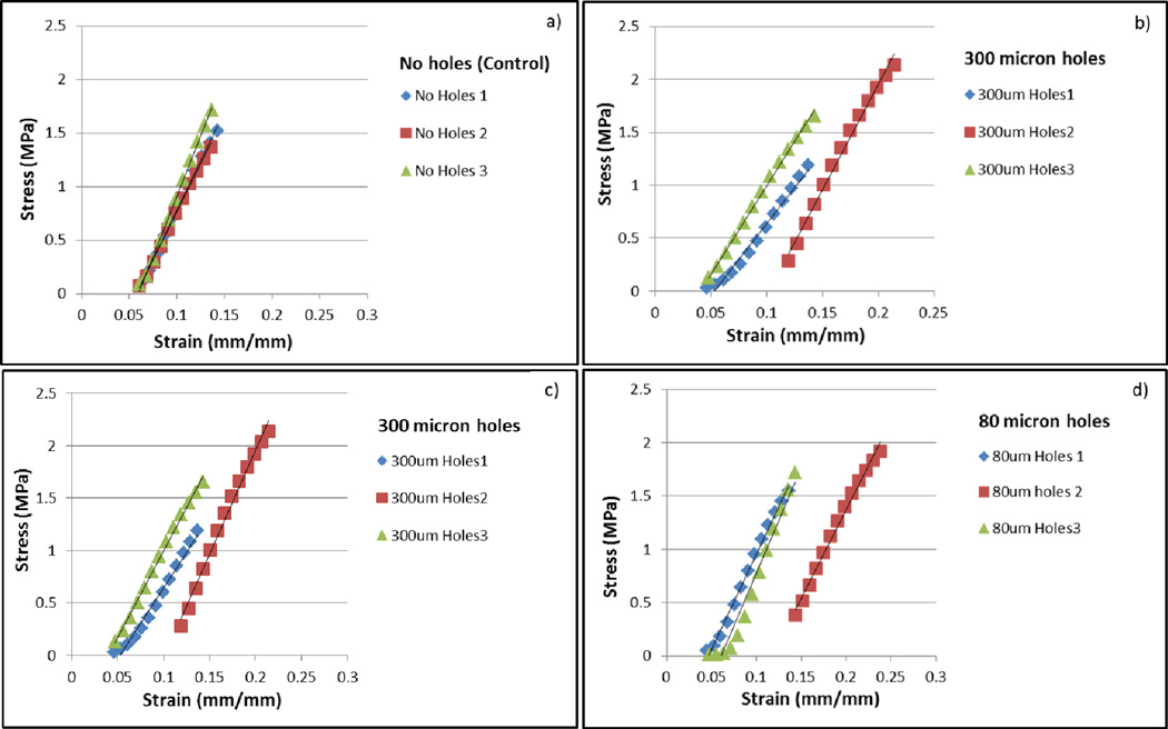
The addition of laser cut pores on electrospun PCL fiber mats led to a reduction in the overall force the mats were able to withstand, however the pores did not change the Young’s modulus. (Table I). A lower maximum force was tolerated by all of the fiber mats with laser cut pores, ranging from 5.1 N to 7 N compared to 9 N for mats without laser cut pores. There was no difference in maximum force due to variations in pore size. No significant difference was observed in Young’s modulus for any of the groups tested (Fig. IX).
Table I.
| Samples | Max Force (N) | Young's Modulus (MPa) |
|---|---|---|
| 80 µm | 6 ± 1 | 18 ± 2 |
| 160 µm | 6.5 ± .5 | 17 ± 1 |
| 300 µm | 5.8 ± .4 | 17 ± 3 |
| No Holes | 9.8 ± .1 | 19 ± 3 |
Figure IX.
Stress-strain relations between the four sample groups. a) Scaffold without laser cut pores, b) Scaffold with 300 µm pores, c) Scaffold with 160 µm pores and d) Scaffold with 80 µm pores.
Discussion
Electrospinning is a simple and rapid method to fabricate tissue engineerined scaffolds, which have high porosity and micron-scale fibers that simulate the extracellular matrix structure of native tissues. The degree of crystallinity and fiber alignment in the polymeric scaffolds is also controllable by electrospinning. Additionally, the simple fabrication methods of electrospinning provide ample opportunity to add drugs, growth factors and other biomolecular signals directly into the polymeric solutions before electrospinning. Some groups have also attempted using multiple solutions to create layered or graded structures. The fibers result in a very high surface area to volume ratios that are good for initial cell attachment, but form dense fiber networks that are relatively impenetrable to cellular infiltration. However, a 3D scaffold structure that mimics the complex in vivo tissue architecture often requires cell migration within the scaffold. Several studies using these scaffolds have identified lack of porosity and small pore sizes as their primary limitation to effective implant development.
There have been several efforts to customize and increase pore sizes of electrospun scaffolds. Kidoaki et al. developed a method to fabricate intricate multilayered scaffolds with Type I collagen, styrenated gelatin and polyurethane [12]. Zhu et al. used a rotating cylinder as a collector and altered the porosity of the resulting scaffolds by tuning the rotational speeds [13]. Nam et al. combined particulate leaching with electrospinning by introducing dry sodium chloride crystals with PCL during electrospinning. Following electrospinning, they leached out the salt particles in water thus forming voids throughout the scaffold. However, this method resulted in non-homogenous porous architecture [14].
To address this issue we fabricated specialized, highly efficient PCL fiber mats with larger pore sizes (80 to 300 µm) and increased porosity by cutting uniformly sized and spaced pores using a laser cutter. We hypothesized that increasing the pore sizes and ensuring uniformly sized/spaced pores, could enhance the cellular infiltration and the vascular ingrowth. Additionally, to closely realize the benefits of these fiber mats in actual cellular microenvironments, we tested them in vivo. The cells and blood vessels seen within our rolled scaffold constructs after their retrieval from rat omentum were exclusively host cells that migrated from the surrounding host tissue. Additionally, PCL is biodegradable by hydrolysis under physiological conditions. It is approved by the Food and Drug Administration for various applications such as drug delivery.
Our goal was to create scaffolds with customizable pore sizes that could be modified for different applications. Depending on the average cell size and other basic considerations, the pore sizes above 80 µm are considered ideal for apposite cellular infiltration. We tried three different pore sizes for the purpose of this study (80 µm, 160 µm and 300 µm). We used scaffolds made by traditional method of simple electrospinning as controls and implanted them in the rat omentum. It was seen that cells from the host were unable to penetrate deep into the control scaffolds; the densely packed fibers and small sized pores inhibited the cell penetration. The cells could only penetrate up to a distance of 350 µm in the absence of the pores. In addition, the number of cells that could penetrate through was much smaller in scaffolds that did not have any LASER cut pores. In rolled scaffolds with 80 µm pores, the cellular penetration was still not significantly higher, but the cell density was greater than controls. Rolled scaffolds with 300 µm pores had 40% more cellualr infiltration than the controls, even in the innermost layers. The cells were seen penetrating a distance of up to 1000 µm into the six layers of the scaffold, which is three times greater than the currently used electrospun scaffolds. Furthermore, significantly high vascular ingrowth to a distance of 850 µm was seen within this group.
The effect of pore diameter independent of pore area suggests that there may be a threshold connectivity which enables optimal cellular penetration.
Further, results from this study show that highly porous electrospun scaffolds can be easily created from relatively non-porous scaffolds without dramatically changing the material properties of the original electrospun polymer. While the maximum force the PCL fiber mats could tolerate decreased with the addition of laser cut pores, the Young’s modulus remained the same. These results suggest that the PCL does not change in chemical structure or crystallinity after application of the laser. Instead, the material melts into a dense ring of polymer around the laser radius. The melted area of the fiber mat helps to explain the decrease in maximum force without a change in inherent properties of the scaffold. In the no laser cut pores control group, stress fractures and breaks in the scaffold are not easily propogated between individual electrospun fibers, while a dense polymer ring easily focuses stress and increases propogation of dislocations during mechanical testing. Our porous electrospun fiber mats show a high retention of material properties compared to other studies, but may be limited to areas of tissue engineering that are not exposed to extremely large forces or cycling.
In this method of developing rolled scaffold constructs for implantation in vivo in rat omentums, the layers of the fiber mats were not bound together firmly. Instead the construct was sutured and sealed with silicone at the ends. This could possibly lead to scaffolds with varying degrees of contacts between layers and subsequently affect cellular infiltration and vascular ingrowth. More robust ways of developing these rolled scaffold constructs would be beneficial to improve their layer-to-layer uniformity. For example, the rolled sheets can be robotically stitched together by 3D stitching machines, or thermally joined at strategic locations to improve macroscopic uniformity. Despite the silicone seal at the two ends, there was still some cellular penetration observed from the ends of the constructs as seen from the slightly high cell density in the group without laser cut pores. Additionally, our method of using a laser cutter to cut holes of desired sizes, shapes and patterns to enhance the porosity of electrospun scaffolds is limited by the lower end threshold of the laser cutter, and the thickness and composition of the material. For this combination of PCL fiber mat and CO2 laser, the smallest pore diameter possible is 80 µm and numerous other lasers are availabe to create finer pores if they are desirable.
Conclusion
In this study, we developed unique macro-porous electrospun fiber mats with enhanced pore sizes and increased porosity. This was accomplished by using an innovative and efficient two-step electrospinning and laser cutting fabrication method. This method did not involve any complex additional steps and thus aided in maintaining the native morphology of the electrospun scaffolds. The scaffolds with 300-µm pores had well-defined, equal-sized, uniformly spaced pores that brought about close to 40% more cellular infiltration and significant vascular ingrowth into the rolled scaffolds as compared to the controls. Further, this method can be adeptly used to create variable pore sizes depending upon the specific tissue engineering application.
Acknowledgements
This work was funded by the National Institutes of Health NIDDK R01 DK083319.
Footnotes
Publisher's Disclaimer: This is a PDF file of an unedited manuscript that has been accepted for publication. As a service to our customers we are providing this early version of the manuscript. The manuscript will undergo copyediting, typesetting, and review of the resulting proof before it is published in its final citable form. Please note that during the production process errors may be discovered which could affect the content, and all legal disclaimers that apply to the journal pertain.
References
- 1.Liang D, Hsiao B, Chu B. Functional electrospun nanofibrous scaffolds for biomedical applications. Advanced Drug Delivery Reviews. 2007;vol. 59(no. 14):1392–1412. doi: 10.1016/j.addr.2007.04.021. [DOI] [PMC free article] [PubMed] [Google Scholar]
- 2.Fridrikh S, Yu J, Brenner M, Rutledge G. Controlling the fiber diameter during electrospinning. Physical Review Letters. 2003;vol. 90(no. 14):4. doi: 10.1103/PhysRevLett.90.144502. Article ID 144502. [DOI] [PubMed] [Google Scholar]
- 3.Kumbar S, James R, Nukavarapu S, Laurencin C. Electrospun nanofiber scaffolds: engineering soft tissues. Biomedical Materials. 2008;vol. 3(no. 3) doi: 10.1088/1748-6041/3/3/034002. Article ID 034002. [DOI] [PubMed] [Google Scholar]
- 4.Li M, Mondrinos MJ, Gandhi MR, Ko FK, Weiss AS. Electrospun protein fibers as matrices for tissue engineering. Biomaterials. 26:5999–6008. doi: 10.1016/j.biomaterials.2005.03.030. [DOI] [PubMed] [Google Scholar]
- 5.Zhang Y, Ouyang H, Lim CT, Ramakrishna S, Huang ZM. Electrospinning of gelatin fibers and gelatin/PCL composite fibrous scaffolds. J Biomed Mater Res B Appl Biomater. 2005;72:156–165. doi: 10.1002/jbm.b.30128. [DOI] [PubMed] [Google Scholar]
- 6.Baker BM, Gee AO, Metter RB, Nathan AS, Marklein RA, Burdick JA. The potential to improve cell infiltration in composite fiber-aligned electrospun scaffolds by the selective removal of sacrificial fibers. Biomaterials. 2008;29:2348–2358. doi: 10.1016/j.biomaterials.2008.01.032. [DOI] [PMC free article] [PubMed] [Google Scholar]
- 7.Wright L, Andric T, Freeman J. Utilizing NaCl to increase the porosity of electrospun materials. Materials Science and Engineering C. 2011;31:30–36. [Google Scholar]
- 8.Leong MF, Rasheed MZ, Lim TC, Chian KS. In vitro cell infiltration and in vivo cell infiltration and vascularization in a fibrous, highly porous poly(d,l-lactide) scaffold fabricated by cryogenic electrospinning technique. J Biomed Mater Res A. 2009;91:231–240. doi: 10.1002/jbm.a.32208. [DOI] [PubMed] [Google Scholar]
- 9.Bowlin GL. Enhanced Porosity without Compromising Structural Integrity: The Nemesis of Electrospun Scaffolding. J Tissue Sci Eng. 2:103e. [Google Scholar]
- 10.Cooper-White JJ, Vaquette C. Increasing electrospun scaffold pore size with tailored collectors for improved cell penetration. Acta Biomater. 2011;7:2544. doi: 10.1016/j.actbio.2011.02.036. [DOI] [PubMed] [Google Scholar]
- 11.Chung AS, Hwang HS, Das D, Zuk P, McAllister DR, Wu BM. 2011. Lamellar stack formation and degradative behaviors of hydrolytically degraded poly (e-caprolactone) and poly (glycolide-e-caprolactone) blended fibers. J Biomed Mater Res Part B. 2011;00B:000–000. doi: 10.1002/jbm.b.31950. [DOI] [PubMed] [Google Scholar]
- 12.Kidoaki S, Kwon IK, Matsuda T. Mesoscopic spatial designs of nano- and microfiber meshes for tissue-engineering matrix and scaffold based on newly devised multilayering and mixing electrospinning techniques. Biomaterials. 2005;26:37–46. doi: 10.1016/j.biomaterials.2004.01.063. [DOI] [PubMed] [Google Scholar]
- 13.Zhu X, Cui W, Li X, Jin Y. Electrospun fibrous mats with high porosity as potential scaffolds for skin tissue engineering. Biomacromolecules. 2008;9:1795–1801. doi: 10.1021/bm800476u. [DOI] [PubMed] [Google Scholar]
- 14.Nam J, Huang Y, Agarwal S, Lannutti J. Improved cellular infiltration in electrospun fiber via engineered porosity. Tissue Eng. 2007;13:2249–2257. doi: 10.1089/ten.2006.0306. [DOI] [PMC free article] [PubMed] [Google Scholar]
- 15.Milleret V, Simona B, Neuenschwander P, Hall H. Tuning electrospinning parameters for production of 3d-fiberfleeces with increased porosity for soft tissue engineering applications. Eur Cell Mater. 2011 Mar 22;21:286–303. doi: 10.22203/ecm.v021a22. [DOI] [PubMed] [Google Scholar]
- 16.Soliman S, Sant S, Nichol J, Khabiry M, Traversa E, Khademhosseini A. Controlling the porosity of fibrous scaffolds by modulating the fiber diameter and packing density. Journal of biomedical materials research a. 2011;vol 96a(issue 3) doi: 10.1002/jbm.a.33010. [DOI] [PubMed] [Google Scholar]
- 17.Eichhorn SJ, Sampson WW. Statistical geometry of pores and statistics of porous nanofibrous assemblies. J R Soc Interface. 2005;2:309–318. doi: 10.1098/rsif.2005.0039. [DOI] [PMC free article] [PubMed] [Google Scholar]
- 18.Teo WE, Ramakrishna S. Porous tubular structures with controlled fibre orientation using a modified electrospinning method. Nanotechnology. 2005;16:918–924. [Google Scholar]
- 19.Lowery JL, Datta N, Rutledge GC. Effect of fiber diameter, pore size and seeding method on growth of human dermal fibroblasts in electrospun poly(ecaprolactone) fibrous mats. Biomaterials. 2010;31:491–504. doi: 10.1016/j.biomaterials.2009.09.072. [DOI] [PubMed] [Google Scholar]
- 20.Shabani I, Haddadi-Asl V, Seyedjafari E, Babaeijandaghi F, Soleimani M. Improved infiltration of stem cells on electrospun nanofibers. Biochem Biophys Res Commun. 2009;382:129–133. doi: 10.1016/j.bbrc.2009.02.150. [DOI] [PubMed] [Google Scholar]
- 21.Whited BM, Whitney JR, Hofmann MC. Pre-osteoblast infiltration and differentiation in highly porous apatite-coated PLLA electrospun scaffolds. Biomaterials. 2011;32(9):2294–2304. doi: 10.1016/j.biomaterials.2010.12.003. [DOI] [PubMed] [Google Scholar]


