Abstract
Forces and stresses generated by the action of myosin minifilaments are analyzed in idealized computer-generated actin bundles, and compared to results for isotropic actin networks. The bundles are generated as random collections of actin filaments in two dimensions with constrained orientations, crosslinked and attached to two fixed walls. Myosin minifilaments are placed on actin filament pairs and allowed to move and deform the network so that it exerts forces on the walls. The vast majority of simulation runs end with contractile minifilament stress, because minifilaments rotate into energetically stable contractile configurations. This process is aided by the bending and stretching of actin filaments, which accomodate minifilament rotation. Stresses for bundles are greater than those for isotropic networks, and antiparallel filaments generate more tension than parallel filaments. The forces transmitted by the actin network to the walls of the simulation cell often exceed the tension in the minifilament itself.
1. Introduction
Force generation due to non-muscle myosin II and actin is essential for key cellular processes, including retraction of the trailing edge during migration, generation of retrograde flow at the leading edge, and the exertion of force on the cell’s environment. Myosin in cells is generally found in polymeric units known as mini-filaments, which contain tens of myosin heads at either end, and have lengths on the order of 0.5 µm. The myosin heads move toward barbed ends of actin filaments. Force generation often involves the action of myosin mini-filaments on parallel or nearly-parallel actin filament arrays. For example, trailing edge retraction relies on non-muscle myosin II in the middle and rear of the cell [1], where filaments are biased toward parallel orientation. Stress fibers, which exert forces on the cell’s environment that may aid mechanosensing, consist of nearly parallel bundles of actin filaments. Traction studies of cells have demonstrated strong correlations between myosin distribution and contraction [2, 3]. These findings have motivated in vitro studies of the combination of mini-filaments with actin bundles and ATP. This combination produces contraction with [4, 5, 6, 7] or without [8] extra passive cross-linkers. Without extra cross-linkers, the mini-filaments themselves, if present at sufficiently high concentration, act as cross-linkers, and this is crucial for generating effective contraction. In recent studies [9], bundles with parallel and antiparallel actin filaments were grown from bars coated with actin nucleation factors. Antiparallel actin filament arrays generated much more contraction than parallel ones. Obtaining a quantitative understanding of the origins of the contractile stress, and the relationship of the molecular-level forces to the macroscopic stresses, is important because it aids analysis of cell migration and mechanosensing. Several studies have addressed the origins of contractile stress in bundled structures. A hydrodynamic theory of linear actin bundles suggested that contraction occurs only if mini-filaments reaching the barbed end stay there [10, 11], and this result was supported by later calculations of myosin patterning in bundles [12]. Other calculations treating one dimensional bundles found that contractility requires nonlinearities such as buckling [13, 14, 6]. However, there have been no studies treating the origin of the contractile stress taking into account the detailed actin network structure, in particular the effects of forces and displacements perpendicular to the bundle. To our knowledge, the only study of the effect of the actin network structure on the macroscopic stress was a generic study indicating the effect of the filament length [15].
A recent treatment of actin filament organization in the presence of myosin clusters used a methodology [16] which is broadly similar to ours in its treatment of myosin motion along actin filaments. They looked at a different limit of actin filament organization in which the filaments are separate and move freely in the presence of drag forces. Thus macroscopic stresses were not calculated in this work.
Previously [17] we analyzed stress generation by a myosin mini-filament in a two-dimensional elastic isotropic actin network. The forces were mainly contractile because the mini-filaments rotated from unstable extensile equilibria to stable contractile equilibria as their heads moved toward actin filament barbed ends. The macroscopic stress often exceeded an estimate based on continuum elasticity, because of force chains connecting the mini-filaments to the walls. Here we extend these calculations to treat bundled structures obtained by restricting the actin filament orientations. In multiple stochastic realizations of actin bundles and myosin mini-filaments in the bundles, we evaluate the mini-filament tension and the forces transmitted to the walls. Our goal is to see to what extent actomyosin contraction in bundles follows from a small, well-justified set of assumptions: i) that myosin heads move toward actin filament barbed ends, ii) that actin filaments are semiflexible polymers with a large stretching modulus, and iii) that the actin filaments form crosslinked bundled structures.
We find that stress generation in bundles differs from that in isotropic networks, in several ways. First, the rotation process bringing myosin mini-filaments in bundles to their final configuration is greatly aided by transverse motion, bending, and stretching of the actin filaments; in networks this rotation occurred with only minimal motion/bending. Second, the average bundle force generated per myosin is much larger than in the networks, and exhibits a strong dependence on the relative orientation of filaments in the bundle. Finally, the largest forces generated by bundles can exceed the tension in the minifilament itself, by a large factor.
2. Methods
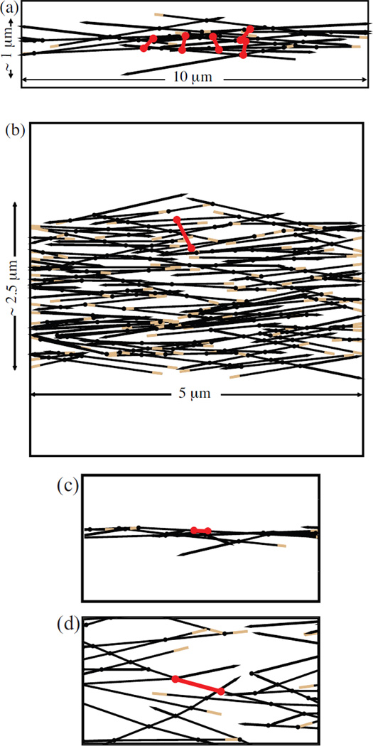
Two-dimensional bundles were generated by modifying the method we used previously for isotropic networks [17], based on Ref. [18]. We first placed filaments with random positions in a two dimensional geometry (see Figs. 1a–b). Their orientations were restricted to be within a cutoff angle θc from the x-axis, but taken random within this window. Filaments extending outside the simulation cell were cropped. Passive crosslinks were placed at filament intersections, with fixed positions along the filaments. Filaments generating extremely short rods were eliminated for computational convenience, where a ”rod” is a filament segment between two crosslinks or a segment between a crosslink and a free end. Because the structure is two-dimensional, it cannot be directly compared to three-dimensional structures of bundles in cells. Therefore we perform calculations for two different bundle geometries. The first is a “thin bundle”. Its width is about 1 µm, and its length is 10 µm. This geometry is designed tomimic as best we can the types of bundles that have been studied in vitro. The second is a “thick bundle”. Its thickness is 2.5 µm and its length is 5µm. This geometry is designed to give the clearest comparison with our previous results for isotropic networks. Although our structures are different from true actin bundles, we term them bundles for simplicity.
Figure 1.
Actin bundles (black lines) with myosin minifilaments (red dumbbells). Barbed ends are colored in brown and pointed ends are drawn as arrowheads. a) Initial configuration of the mini-filaments before relaxation for a thin bundle. b) Initial configuration for a thick bundle. c) Final configuration of a mini-filament in a thin bundle. d) Final configuration of a mini-filament in a thick bundle.
Next the network was randomly scanned for pairs of points on different filaments that could be linked by myosin minifilaments. The two ends of a minifilament were placed at a random pair of points having distance within 10% of the average equilibrium minifilament length L̄m. New, mobile crosslinks were created at these points. This process was repeated for each myosin. The positions of the myosin minifilament ends were defined by dimensionless variables Mj, the distance to the barbed end of the actin filament measured in units of the size of a single actin subunit. For thin bundles, we typically treated five myosins, to have the same number of mini-filaments per unit length as in the experiments of [8]. For thick bundles, we treated a single myosin for comparison with our previous results for isotropic networks. These results are relevant to real bundles because the stress contributions from different myosin minifilaments are additive to a good approximation (see Supporting Material).
The myosin heads at the minifilament ends were then moved, and the actin network relaxed, according to forces from the stretching (Estretch) and bending (Ebend) energies of actin filaments, the myosin minifilament stretching energy Em, and an ATP-based motor energy Emotor driving myosin heads toward barbed ends. Because myosin motors are out of equilibrium, they are not rigorously described by an energy function. Therefore Emotor should be thought of as a “pseudo-energy” which gives the correct mechanical equilibrium, rather than as a physical energy. We allowed the rods to rotate freely at crosslinks. We took Estretch to be quadratic in the length changes ΔLi of the rods. We took Ebend to be quadratic in the angle changes Δθj between rods on the same filament, and inversely proportional to the average length L̄j of the two rods on either side of a crosslink. For the mini-filament stretching energy, we took, for computational convenience, a form that is quadratic for small changes of the mini-filament length Lm, but has a different form for larger changes. We described the myosin motion by a motor energy proportional to Mj. Thus the total energy is:
| (1) |
| (2) |
where is the initial length of a rod, Nr is the total number of rods, Nc is the number of crosslinks, and is the initial mini-filament length. The parameters are as follows: µ is the stretching modulus, κ is the bending modulus, γ is the minifilament stretching energy constant, δ is the size of an actin subunit, FATP is the stall force of one end of the minifilament, and the last term has units of energy because M1 and M2 are dimensionless. For each bundle we then evolved the system to a stable steady state minimizing Etot. Myosin motion along filaments, described by the Mj, was treated separately from elastic relaxation of the actin filaments, because the latter process is much faster. For each set of values of Mj, the actin network was relaxed using a nonlinear conjugate-gradient method [19] based on the crosslink positions, until the sum of the squares of the forces became less than 10−12pN2. Etot and its derivatives with respect to the Mj (generalized forces) were calculated. In this way a force balance was achieved at each crosslink. The forces at each crosslink include stretching forces from the rods touching the link, as well as bending forces from the two filaments involved in the crosslink.
The Mj then followed a steepest-descent algorithm driven by the generalized forces, until each generalized force became less than 10−6pN µm. Mini-filaments were allowed to jump freely over crosslinking points. We assumed that mini-filaments reaching the barbed ends of actin filaments stay there and act as passive crosslinkers. Below we discuss the effects of making the opposite assumption, that mini-filaments reaching the barbed ends leave the simulation box.
In the final configuration, we evaluated the tension Tm in the mini-filaments and two measures of the macroscopic stress on the walls: i) The stress (or linear force density)
| (3) |
where f⃗i is the force exerted by a rod on the wall, r⃗i is the position of a rod-wall contact point, A is the area of the bundle, and the sum is over all points where actin filaments contact the edges of the simulation cell. We calculate this quantity for comparison with our previous results for random networks [17]. ii) The x-components Fwall of the total force on either side of the bundle. We repeated the simulation run 500 times using different random seeds and choices between possible myosin positions. For comparison, we also present data for networks obtained from 250 simulation runs.
The parameter values were as follows. The bending modulus was given the measured value κ = kBTlp, where lp ≃ 15µm [20]. Because use of the experimental value of µ (45 nN [21]) led to slow convergence of the elastic relaxation, we used a smaller value µ = 600 pN, which is still large enough that filament stretching is negligible compared to bending. For thin bundles, we used actin filament lengths of 5 µm, commensurate with values used in in vitro studies. For thick bundles we used actin filament lengths of 2 µm for comparison with our previous work. We used an average minifilament size of [22]. To check the effect of the unknown myosin stiffness parameter γ, its value was varied from our baseline value of 60 pN/µm3. We varied FATP over a range on the order of pN, which corresponds to myosin heads with a low duty ratio. We used cutoff angles θc of 20° for thin bundles and 30° for thick bundles, and also evaluated the effects of using different values.
3. Results and Discussion
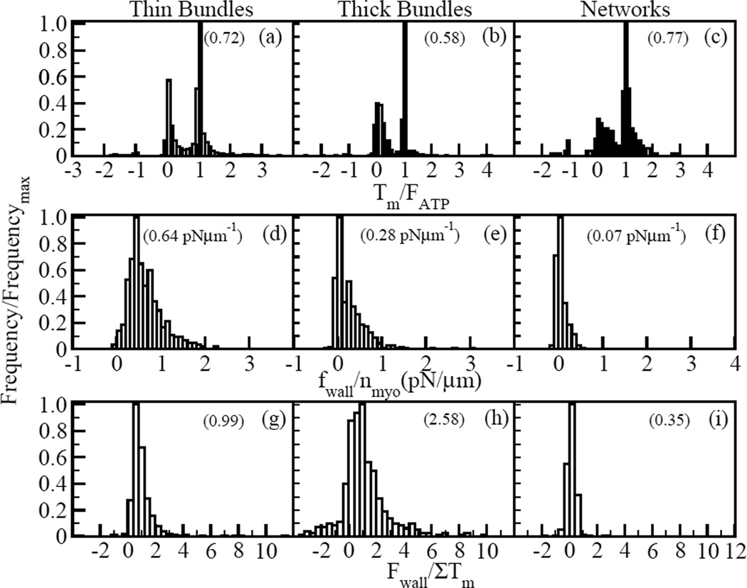
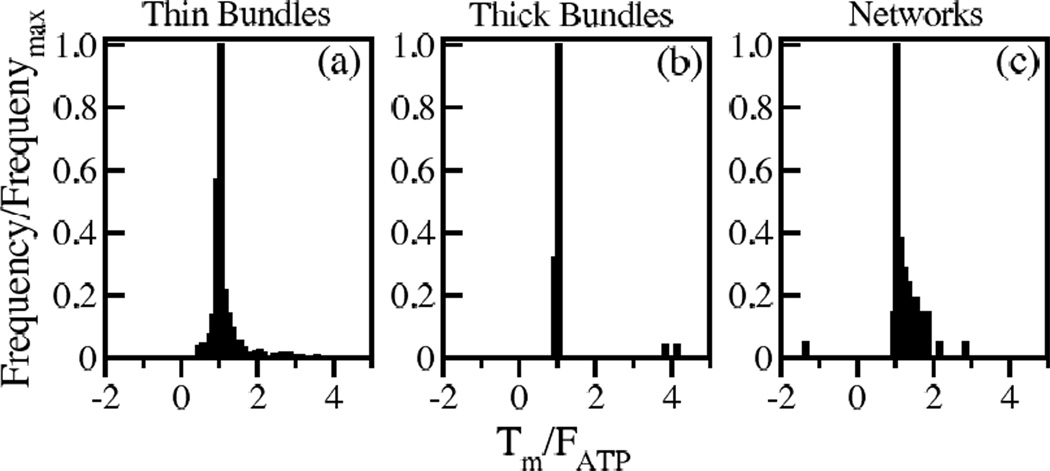
Fig. 2 summarizes our main findings. It compares the distribution of minifilament tension Tm (a–c), force density on walls fwall (d–f), and total pulling force on each wall Fwall (g–i), in thin and thick bundles, to our previous results for networks [17]. The following are the key results, which we explain in more detail below:
Tm, fwall, and Fwall in bundles are overwhelmingly contractile, as for isotropic networks. In thin bundles, these quantities are contractile in 99% of the cases. In thick bundles, 85% of the runs had contractile fwall and Fwall, while 90% had contractile Tm. For networks these fractions are 70% and 91% respectively.
The results for bundles differ from networks in that the distribution of Tm is narrower and has more pronounced peaks at Tm = FATP and Tm = 0. The mean fwall and Fwall are also larger. The mean Fwall in thin bundles is close to the sum of the minifilament tensions.
The forces exerted on the walls in bundles, particularly thick ones, often exceed the sum of the mini-filament tensions (see Fig. 2g–h).
Figure 2.
Histograms of myosin tension, force density and wall force. Frequency for all histograms is scaled by the maximum frequency. Data is shown for 500 runs for thin bundles (with five mini-filaments), 500 runs for thick bundles (with one minifilament) and 250 runs for networks (with one mini-filament). Positive tension and force correspond to contraction. Myosin mini-filament tension scaled by myosin stall force for a) thin bundles, b) thick bundles, and c) networks. Mean values are 0.72, 0.58, and 0.77, respectively. Force density on walls per minifilament for d) thin bundles, e) thick bundles, and f) networks. Mean values are 0.64 pNµm−1, 0.28 pNµm−1, and 0.07 pNµm−1, respectively. Wall force scaled by sum of myosin tensions for g) thin bundles, h) thick bundles, and i) networks. Mean values are 0.99, 2.58, and 0.35, respectively. (About 10 runs in h) which gave values greater than 10 were omitted for clarity. These values were exaggerated because they are due to very small Tm values of mini-filaments that moved to dangling ends, rather than to amplification by the network effects.)
3.1. Origin of Contractile Force
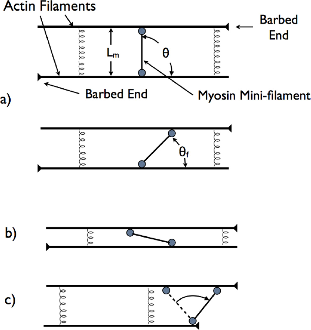
In our previous work for isotropic networks [17], we found that mini-filaments starting in extensile configurations rotate into contractile configurations because this process lowers Emotor. In the present calculations for bundles, a modification of this mechanism operates. Consider the model shown in Fig. 3a, with a minifilament moving along two parallel actin filaments (see Movies S1 and S2 in the Supporting Material). The actin filaments are connected by a linear spring which has its equilibrium separation at their initial separation (before myosin attachment). In the initial configuration, the mini-filament has just attached, perpendicular to the filaments. The mini-filament has an extremely small moment of inertia, and therefore must experience essentially zero torque. Therefore it exerts no horizontal forces on the actin filament when it begins to rotate. The filaments are at their equilibrium separation, so there are no vertical forces either. We analyze the mini-filament motion using an energy function containing Emotor, and a quadratic elastic term with spring constant kspring describing the distortion of the actin network. Since the filaments are oppositely directed, is independent of mini-filament position. Therefore,
| (4) |
so that
| (5) |
Figure 3.
Schematic of mini-filament rotation mechanism leading to contractile stress. a) Initial configuration with mini-filament perpendicular to two antiparallel filaments. b) Final configuration where mini-filament has rotated. c) Initial configuration where mini-filament is nearly parallel to actin filaments. d) Rotation mechanism when one mini-filament head stops at an actin filament barbed end.
This is positive at the starting point θ = π/2. Therefore θ will initially decrease since this reduces . The final value θf of θ (Fig. 3b) will be determined by the competition between Emotor and the elastic term.
To calculate Tm at θf, we note that in equilibrium the forces exerted by the actin filaments on the heads are equal and opposite, and oriented parallel to the mini-filament (because the torque on the mini-filament must vanish). The x-direction force on the upper head from the actin filament is +FATP. Because the total force from the actin filament onto this head must point parallel to the minifilament, and its magnitude equals the tension Tm, force balance in the x-direction gives Tm cos θ = FATP, so that
| (6) |
This force tends to extend the mini-filament, so the mini-filament exerts a contractile force on the network. Note that Tm can exceed FATP.
A related mechanism operates if the initial minifilament orientation is parallel to the actin filaments (Fig. 3b, Movie S3, and Movie S4) so that θ ≃ π, and the equilibrium spacing between the filaments is small (we approximate it as zero). Then the energetics of θ dropping from π are described by
| (7) |
The initial configuration will be unstable if is reduced by small changes in θ. This will occur if
| (8) |
In the initial drop of θ from π, the forces driving the minifilament heads compress the mini-filament, leading to extensile stress on the network. However, as θ decreases, one readily shows that remains positive, so that θ will eventually drop to 0. At this point, the stress is contractile.
These two mechanisms operate if the mini-filament comes to equilibrium away from the barbed end of either of the two actin filaments. In our simulations, this happens almost only for antiparallel filaments. For parallel filaments, another mechanism can operate if myosin heads reaching a barbed end remain attached. In this mechanism [10], shown in Fig. 3c, Movie S4, and Movie S5, a mini-filament moves toward the barbed ends of two filaments, and one of the heads (the bottom head in Fig. 3c) reaches a barbed end and stops. If the top myosin head is ahead of the bottom head, it will be pulled forward and thus in turn pull on the bottom head, giving a contractile Tm. If the bottom myosin head is ahead of the top head (dashed line), then, if kspring is small enough, the minifilament will rotate into a contractile configuration and continue to move toward the end. Although myosin heads stopping at barbed ends can generate extensile stress, the average contribution should be contractile, and our simulation results confirm this.
Under what circumstances will these rotation mechanisms operate? The first will always operate for an appropriately oriented mini-filament, because the initial barrier to rotation vanishes. The second mechanism (and the variant of the third mechanism in which the minifilament is intially extensile) will operate if the spring constant kspring describing resistance to network deformation is small enough. This deformation arises mainly from filament bending. The resistance to deformation will decrease with increasing rod length Li. Analysis of filament bending mechanics [23] predicts that , giving an instability criterion of
| (9) |
In our simulations, lp = 15µm, Lm = 0.4µm, and Li ≃ 1µm, which gives . Thus mini-filament rotation should be very common. Note that the bending of filaments whose ends are nearly fixed is aided by filament stretching. In these cases, filament stretching also contributes to the rotation mechanisms.
3.2. Origins of two-peaked Tm distribution in bundles
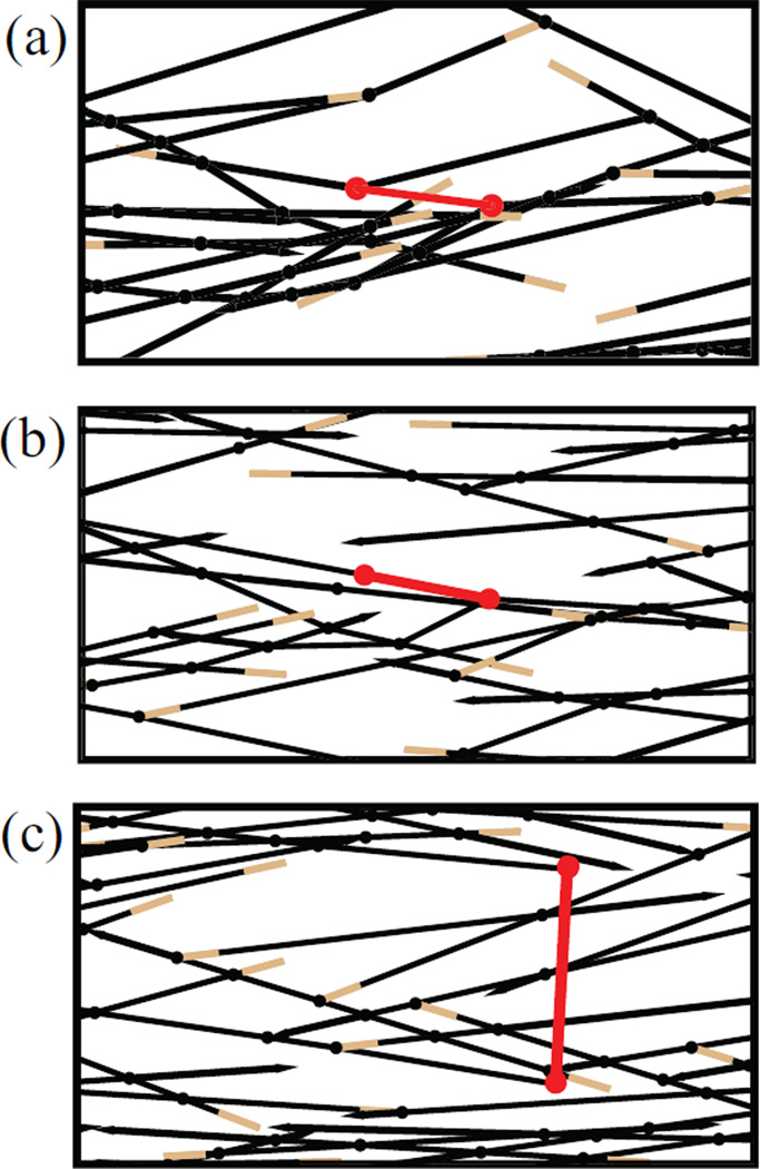
This results from the distribution of positions of mini-filaments relative to actin filament tips, and the relative orientations of the mini-filaments and actin filaments. The mini-filament positions relative to the actin filament tips affects force generation, because myosin heads at the filament tips generate less force. This behavior is described in Table 1, where “ends” refers to the ends of the mini-filament (not actin filaments), see Fig. 4. Category A, “Both ends went to equilibrium” includes the cases where both ends of the mini-filament reached equilibrium points, away from the tips of the actin filaments to which they are attached. This occurs mainly for antiparallel filaments. The fraction in category A is greater in thin bundles than thick bundles because the filaments are longer. This category has the largest mean Tm, and its fractional contribution to the average Tm is about 30% in thin bundles and networks, but smaller in thick bundles.
Table 1.
Statistics for different categories of final mini-filament configurations for bundles and networks. A: Both ends went to equilibrium B: One end went to equilibrium C: Both ends got stuck
| (a) Thin bundles | |||
|---|---|---|---|
| Category | Percentage | Mean Tm | Weighted Tm |
| A | 28% | 1.11 | 0.31 |
| B | 39% | 0.94 | 0.36 |
| C | 33% | 0.14 | 0.05 |
| (b) Thick bundles. | |||
| Category | Percentage | Mean Tm | Weighted Tm |
| A | 7% | 1.19 | 0.08 |
| B | 37% | 0.95 | 0.35 |
| C | 56% | 0.25 | 0.14 |
| (c) Isotropic Networks. | |||
| Category | Percentage | Mean Tm | Weighted Tm |
| A | 25% | 1.25 | 0.31 |
| B | 36% | 0.90 | 0.33 |
| C | 39% | 0.33 | 0.13 |
Figure 4.
Simulation snapshots for different final mini-filament configurations a) Both ends went to equilibrium. b) One end went to equilibrium. c) Both ends got stuck. Color scheme is as in Fig. 1.
The mini-filaments in Category B have one end stuck at the barbed end of actin filament while the other end reaches an equilibrium position away from the end. This can occur with either parallel or antiparallel actin filaments. In the antiparallel case it happens most often when one of the mini-filament ends begins close to the barbed end. That mini-filament end reaches the barbed end and stays attached, while the other end keeps moving until it reaches equilibrium. The fraction of such mini-filaments is 35–40% in all three geometries, and the mean Tm values are also similar, about 20–30% smaller than in Category A.
Category C, where both ends of the mini-filament are stuck at filament tips, is substantial in all three geometries. This category has the smallest mean Tm. The mini-filaments in this category are responsible for the peak in the Tm distribution near Tm = 0.
The results for Categories B and C depend on the assumption that mini-filaments reaching the barbed ends of actin filaments stay there as passive crosslinkers. If we instead assume that mini-filaments reaching the barbed ends leave the simulation box, then only Category A is present. In this case, as seen in Table 1, the averaged Tm is increased, by an amount ranging from about 50% to 100%. The fraction of contractile Tm increases to over 98% in all geometries. Fig. 5 shows the distribution of Tm/FATP in this case for all geometries.
Figure 5.
Distribution of mini-filament tension scaled by the stall force for model where minifilaments are not allowed to stay at filament tips. (a) for thin bundles. (b) for thick bundles (c) for networks. mean values are 1.11, 1.19 and 1.25 respectively. Frequency is scaled by the maximum frequency for each case.
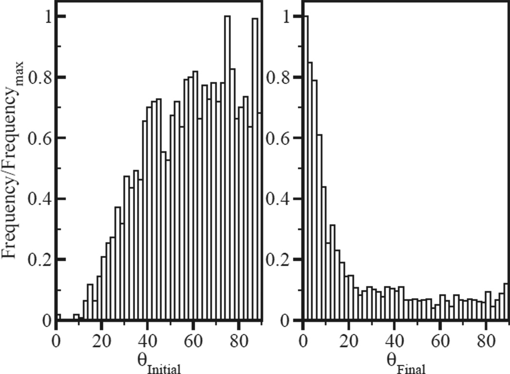
The mini-filament orientation is important because the mini-filament tension depends on its angle relative to the actin filaments. As seen in Fig. 6a the initial mini-filament orientations are mainly perpendicular to the bundle, due to the increased probability of finding two rods at a distance matching the mini-filament size. But during relaxation (Fig. 6b), mini-filaments tend to rotate to reach a final configuration nearly parallel to the bundle. For such orientations, the tension is generally close to the myosin stall force FATP, as expected from Eq. (6). By contrast, in networks, the final distribution of mini-filament orientations relative to the actin filaments is isotropic. Mini-filaments in networks can reach equilibria on nonparallel actin filaments where Tm greatly exceeds FATP [17]. This occurs much less in bundles, causing a more pronounced peak at Tm = FATP in the Tm distribution, as seen in Fig. 2a–b.
Figure 6.
a) Distribution of mini-filament orientation relative to horizontal before relaxation. Mean angle is 59°. b) Same, after relaxation. Mean angle is 23°.
3.3. Origins of larger fwall and Fwall in bundles
This occurs because of a combination of three effects. First, the nearly parallel orientation of actin filaments in bundles, mentioned above, enhances their ability to transmit force to the walls. Force can be transmitted directly along chains of filaments to the walls, with smaller counterbalancing elastic forces than would be present in isotropic networks. This mechanism increases fwall and Fwall relative to their values in networks. Second, the contact area with the simulation walls is smaller in the bundles than in the isotropic networks. This results in larger forces on the side walls (Fig. 2g–i), because the contractile force from a minifilament is spread out over two walls rather than four. In addition, the smaller area results in a larger stress (see Fig. 2d) for the thin bundles. Finally, as described in the next subsection, minifilaments in certain bundle configurations can exert very large wall forces relative to their tension.
3.4. Large magnitude of wall forces compared to Tm
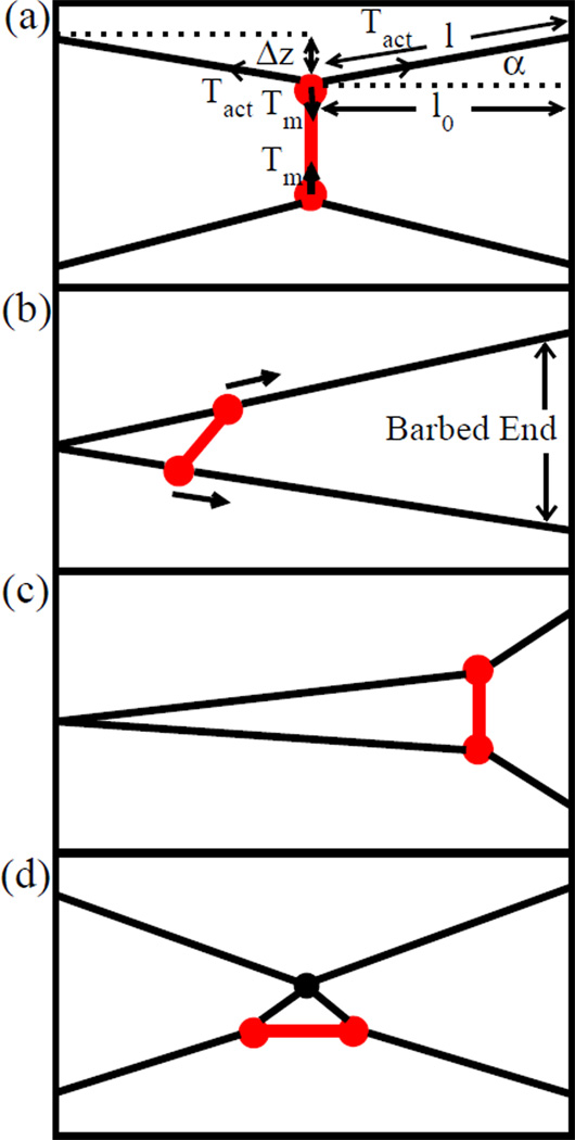
The wall forces Fwall in bundles, particularly thick bundles (Fig. 2h), are often much larger than the minifilament tension Tm. In some cases, this occurs because the tension is small (Tm << FATP). But it also occurs in many cases where Tm ≃ FATP. In the latter cases, Fwall can exceed the product (number of minifilaments) × FATP. The large wall forces occur because of a coupling between mini-filament forces transverse to the actin filaments, and stresses along the actin filaments. To understand this effect, we treat a model of a mini-filament as a force dipole exerting transverse forces on two parallel actin filaments, as shown in Fig. 7a. The model treats forces due to bending and stretching of the filaments. The solution is presented in the Supporting Material. In the limit of small Tm, one obtains
| (10) |
and for large Tm,
| (11) |
Figure 7.
Force amplification by bundled crosslinking geometry a) Schematic diagram of a force dipole acting in the middle of two parallel actin filaments. b) Initial orientation of mini-filament in asymmetric geometry. c) Final orientation of minifilament in asymmetric geometry. d) Minifilament with a horizontal orientation.
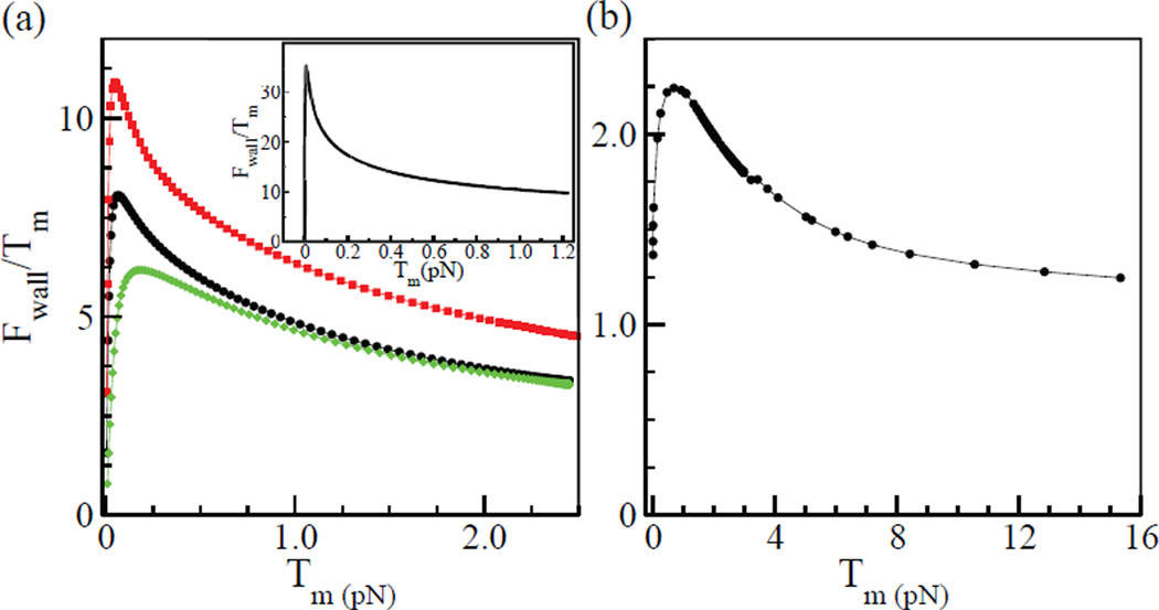
The crossover between these limits occurs as the restoring force changes from bending-dominated to stretching-dominated. The peaked behavior of Fwall/Tm is illustrated in the inset of Fig. 8a. We have also treated numerically a less symmetric configuration (Fig. 7b and c), and one with a minifilament parallel to the bundle (Fig. 7d). Fig. 8a shows that Fwall/Tm has a similar peaked dependence on Tm for the geometry of Fig. 7b, and this holds for the other geometries as well. In all cases Fwall reaches values much larger than Tm.
Figure 8.
a) Variation of Fwall/Tm with Tm for geometry of Fig. 7b. Black curve (dots): κ = 0.06 pNµm2 and µ = 600 pN. Red curve (squares): κ = 0.06 pN µm2 and µ = 1200 pN. Green curve (diamonds): κ = 0.12 pN µm2 and µ = 600 pN. Inset shows theoretical prediction for for geometry of Fig. 7a as calculated in the Supporting Material. b) Variation of Fwall/Tm with Tm for a sample thick bundle with a single mini-filament.
We evaluate the crossover tension between the limits of large and small Tm, as the value of Tm where the estimates of Eqs. (10) and (11) are equal: , so that . For our parameters, . We conjecture that mini-filaments will be in the large Tm limit when the transverse component of the mini-filament tension exerted on the actin filament exceeds . This will occur for a large fraction of the mini-filaments. For these mini-filaments, Eq. (11) holds, and since µ >> Tm they will have Fwall >> Tm. The red and green curves in Fig. 8a, which correspond to doubling µ and κ respectively, confirm the prediction of Eq. (11) that for large Tm, Fwall ∝ µ−1/3. Note that in this limit, filament bending occurs freely in comparison with stretching, so that the filaments are significantly bent.
To assess the relevance of this simple model to our simulations, we varied the minifilament tension in a given network artificially by changing the initial mini-filament length . The results, shown Fig. 8b, are generally consistent with the theoretical predictions. As in the simpler model results shown in Fig. 8a, Fwall initially increases with Tm but turns over at larger values of Tm. However, the enhancement of Fwall is smaller than in the model calculations. This probably occurs because we do not have single filaments reaching wall to wall, but rather chains of filaments. The effective stretching modulus µeff should be lower than that of single filament, which would lead to both smaller Fwall and larger Tm values at the maximum, as seen in the simulations. We are not aware of calculations of µeff, but related work has treated the shear bending modulus of semiflexible polymer bundles [24].
This effect is much smaller in networks and thin bundles than in thick bundles. We believe that this is because the mechanism, as illustrated in Fig. 7, requires resistance to vertical deformation of the bundle. If the wall attachment points in the figure could move freely, there would be no amplification. The thin bundles usually become much narrower as a result of the myosin forces, suggesting that their resistance to vertical deformation is low, which would explain why they have less force amplification.
3.5. Robustness of results to assumptions made
We have evaluated the robustness of our results by varying our input parameters and assumptions. With increasing FATP, fwall and Fwall increased sub-linearly, maintaining contractility. For thin and thick bundles, Tm/FATP decreased by about 5% and 20% respectively when FATP was doubled. With increasing FATP, more mini-filaments reach filament ends where they generate less force. This effect is smaller in thin bundles because their filaments are longer. Doubling γ changed fwall and Tm by less than 1%. Doubling the length of thin bundles by 100%, while doubling the number of myosins, did not change the mean Tm or Fwall significantly. Thus the bundle acts as two “contractile units” [8, 14] of length 10 µm in series, each generating the same stress. Increasing the length of a thick bundle containing a single mini-filament by 40% decreased both the wall forces and Tm by about 15%. Changing the maximum angle of span θc for actin filaments in bundles had moderate effects. Decreasing θc by 50% led to a 10% increase in fwall but a 10% decrease in Tm. The reduction in Tm occurs because smaller values of θc allow more mini-filaments to end up at actin filament ends. Increasing θc by 50% led to a 5% decrease in fwall but a 20% increase in Tm. The effect of the assumption that mini-filaments always stay at actin filament barbed ends was discussed above in connection with Table 1.
We have also investigated the effects of the assumption that myosins move freely over crosslinks. We find that when such motion is blocked, the mean TM/FATP is reduced by 25% in thick bundles and 5% in thin bundles. We believe that the smaller difference in thin bundles occurs because the crosslinker spacing is larger than in thick bundles. This means that crosslinks have a weaker effect on force generation. Furthermore, in thin bundles where one end of a minifilament is stuck at a crosslink, the other end often continues to move in such a way that the minifilament is horizontal and the force is close to Tm, which in turn is close to the average value.
One assumption that we cannot easily vary is that of a static actin network, without treadmilling or crosslinker dynamics. Because myosin moves toward barbed ends, where treadmilling filaments grow, treadmilling should enhance the fraction of filaments equilibrating on two filaments (Category A above), as opposed to reaching the ends of the filaments. This would increase the contractile stress, as was argued in Ref. [25]. Crosslinker dynamics could include either elastic stretching of crosslinks, or crosslinker release. We believe that the elastic effect is small. Simulation studies of α-actinin [26] have suggested that even at forces of 50 pN, the stretching is only about 25% of the original length, or about 19 nm, much less than the rod lengths in the simulation. There could also be an energy penalty associated with relative rotation of different filaments (not bending) at a crosslink. For α-actinin, rotation is believed to be fairly unconstrained [27], so this effect should not be large. However, for more directional crosslinkers such as fascin the effect would be much larger and the simulation results might change substantially. The effects of crosslinker release will depend on the timescale of this processes relative to the time scale of mini-filament motion. If crosslinker release is slow in comparison with mini-filament motion, the current results will hold. If the crosslinker release is more rapid, it might prevent the propagation of force from the myosins to the walls, and thus reduce the contractile stress.
4. Conclusions
The calculations described above have shown that a minimal model, based on the motion of myosin heads toward barbed ends of actin filaments and actin filament flexibility, leads to contractile behavior in bundle-like structures. Our finding that contraction is practically universal is consistent with numerous in vitro studies which have found contractile stress. The mechanism seen here is also different from that of Refs. [10, 11], which was based on interactions between parallel filaments caused by binding of myosins to barbed ends. In the present mechanism, contraction results more from myosin motion on antiparallel filaments than on parallel filaments. We find that the average Tm value for parallel filaments is only about 70% of that for antiparallel filaments. Furthermore, generation of contraction by parallel filaments will be greatly reduced if myosin heads leave barbed ends.
Because the model is highly idealized, we cannot make quantitative predictions for the forces. However, for thin bundles, the results of Fig. 2 imply that the average wall force is about 0.7nmyoFATP, where nmyo is the number of mini-filaments in a contractile unit. This is roughly consistent with the analysis of Ref. [8].
Our results are also relevant to recent in vitro studies [9] in which actin filaments were grown off rods coated with actin-polymerization nucleators. Three distinct structures were formed in different regions: branched networks, parallel bundles, and antiparallel bundles. It was found that antiparallel bundles generated the strongest contraction, while branched networks had weaker contraction, and parallel bundles were comparatively unaffected by myosin. These findings are consistent with our predictions that antiparallel filament arrangements contract more strongly than networks or parallel arrangements. However, myosin does contract parallel actin filaments in the simulations if it remains attached at barbed ends (Fig. 3d). Therefore, the experimental results suggest that myosin leaves barbed ends when it reaches them. We also note recent studies [28] showing that Arp2/3 complex, which generates branched networks, inhibits myosin-dependent retrograde flow. This may be because networks contract less efficiently than bundles.
The present model also predicts that a longer distance between crosslinks will enhance the mini-filament rotation instability and thus favor contraction (see Eq. (9)). This is consistent with experimental observations [6] that, although crosslinkers are required for contractility, a very large density of crosslinkers prevents contraction.
Another prediction of the model is that bundles can amplify the force generated by mini-filaments. This prediction is not very general since, of the three cases we considered, large amplification occurred only in the thick bundles. Nevertheless, we note that in the experiments of Ref. [20], forces of about 1 piconewton per myosin head were measured. If the duty ratio of myosin is low, as is generally believed, then such large forces would be unlikely. The amplification mechanism discussed here may be relevant to these results.
Supplementary Material
Acknowledgement
This work was supported by the National Institutes of Health under Grant Number R01 GM086882.
References
- 1.Svitkina T, Verkhovsky AB, McQuade KM, Borisy GG. Analysis of the actin-myosin ii system in fish epidermal keratocytes: mechanism of cell body translocation. J. Cell. Biol. 1997;139(2):397–415. doi: 10.1083/jcb.139.2.397. [DOI] [PMC free article] [PubMed] [Google Scholar]
- 2.Schaub S, Bohnet S, Laurent VM, Meister JJ, Verkhovsky AB. Comparative maps of motion and assembly of filamentous actin and myosin ii in migrating cells. Mol. Biol. Cell. 2007;18(10):3723–32. doi: 10.1091/mbc.E06-09-0859. [DOI] [PMC free article] [PubMed] [Google Scholar]
- 3.Fournier MF, Sauser R, Ambrosi D, Meister JJ, Verkhovsky AB. Force transmission in migrating cells. J. Cell. Biol. 2010;188(2):287–97. doi: 10.1083/jcb.200906139. [DOI] [PMC free article] [PubMed] [Google Scholar]
- 4.Gardel ML, Kasza KE, Brangwynne CP, Liu J, Weitz DA. Biophysical tools for biologists, volume two: In vivo techniques. Methods in Cell. Biol. 2008;89:487–519. doi: 10.1016/S0091-679X(08)00619-5. [DOI] [PMC free article] [PubMed] [Google Scholar]
- 5.Mizuno D, Tardin C, Schmidt CF, MacKintosh FC. Nonequilibrium mechanics of active cytoskeletal networks. Science. 2007;315:370–373. doi: 10.1126/science.1134404. [DOI] [PubMed] [Google Scholar]
- 6.Bendix PM, Koenderink GH, Cuvelier D, Dogic Z, Koeleman BN, Brieher WM, Field CM, Mahadevan L, Weitz DA. A quantitative analysis of contractility in active cytoskeletal protein networks. Biophys J. 2008;94:3136. doi: 10.1529/biophysj.107.117960. [DOI] [PMC free article] [PubMed] [Google Scholar]
- 7.Janson LW, Kolega J, Taylor DL. The role of solation-contraction coupling in regulating stress fiber dynamics in nonmuscle cells. J. Cell. Biol. 1991;114:1005–1015. doi: 10.1083/jcb.114.5.993. [DOI] [PMC free article] [PubMed] [Google Scholar]
- 8.Thoresen T, Lenz M, Gardel ML. Reconstitution of contractile actomyosin bundles. Biophys. J. 2011;100:2698–2705. doi: 10.1016/j.bpj.2011.04.031. [DOI] [PMC free article] [PubMed] [Google Scholar]
- 9.Reymann AC, Boujemaa-Paterski R, Martiel J-L, Guerin C, Cao W, Chin HF, De La Cruz EM, Thery M, Blanchoin L. Actin network architecture can determine myosin motor activity. Science. 2012;336:1310–1314. doi: 10.1126/science.1221708. [DOI] [PMC free article] [PubMed] [Google Scholar]
- 10.Kruse K, Julicher F. Actively contracting bundles of polar filaments. Phys. Rev. Lett. 2000;85(4):1778–1781. doi: 10.1103/PhysRevLett.85.1778. [DOI] [PubMed] [Google Scholar]
- 11.Kruse K, Julicher F. Self-organization and mechanical properties of active filament bundles. Phys. Rev. E. 2003;67:051913. doi: 10.1103/PhysRevE.67.051913. [DOI] [PubMed] [Google Scholar]
- 12.Zemel A, Mogilner A. Motor-induced sliding of microtubule and actin bundles. Phys. Chem. Chem. Phys. 2009;11:4821–4833. doi: 10.1039/b818482h. [DOI] [PMC free article] [PubMed] [Google Scholar]
- 13.Lenz Martin, Gardel Margaret L, Dinner Aaron R. Requirements for contractility in disordered cytoskeletal bundles. New Journal of Physics. 2012;14(3):033037. doi: 10.1088/1367-2630/14/3/033037. [DOI] [PMC free article] [PubMed] [Google Scholar]
- 14.Lenz M, Thoresen T, Gardel ML, Dinner AR. Contractile units in disordered actomyosin bundles arise from f-actin buckling. Phys. Rev. Lett. 2012;108:238107. doi: 10.1103/PhysRevLett.108.238107. [DOI] [PMC free article] [PubMed] [Google Scholar]
- 15.Carlsson AE. Contractile stress generation by actomyosin gels. Phys. Rev. E. 2006;74:051912. doi: 10.1103/PhysRevE.74.051912. [DOI] [PubMed] [Google Scholar]
- 16.Gordon D, Bernheim-Grosswasser A, Keasar C, Farago O. Hierarchical self-organization of cytoskeletal active networks. Phys. Biol. 2012;9:026005. doi: 10.1088/1478-3975/9/2/026005. [DOI] [PubMed] [Google Scholar]
- 17.Dasanayake NL, Michalski PJ, Carlsson AE. General mechanism of actomyosin contractility. Phys. Rev. Lett. 2011;107:118101. doi: 10.1103/PhysRevLett.107.118101. [DOI] [PMC free article] [PubMed] [Google Scholar]
- 18.Head DA, Levine AJ, Mackintoch FC. Distinct regimes of elastic response and deformation modes of cross-linked cytoskeletal and semiflexible polymer networks. Phys. Rev. Lett. 2003;68:061907. doi: 10.1103/PhysRevE.68.061907. [DOI] [PubMed] [Google Scholar]
- 19.Press WH, Teukolsky SA, Vetterling WT, Flannery BP. Numerical Recipes in C. second edition. Cambridge: Cambridge University Press; 1992. [Google Scholar]
- 20.Koenderink GH, Dogic Z, Nakamura F, Bendix PM, Mackintosh FC, Hartwig JH, Stossel TP, Weitz DA. An active biopolymer network controlled by molecular motors. PNAS. 2009;106(36):15192–15197. doi: 10.1073/pnas.0903974106. [DOI] [PMC free article] [PubMed] [Google Scholar]
- 21.Kojima H, Ishijima A, Yanagida T. Direct measurement of stiffness of single actin filaments with and without tropomyosin by in vitro nanomanipulation. Proc. Natl. Acad. Sci. 1994;91:12962–12966. doi: 10.1073/pnas.91.26.12962. [DOI] [PMC free article] [PubMed] [Google Scholar]
- 22.Korn ED, Hammer JA. Myosins of nonmuscle cells. Ann. Rev. Biophys. Biophys. Chem. 1988;17:23–45. doi: 10.1146/annurev.bb.17.060188.000323. [DOI] [PubMed] [Google Scholar]
- 23.Mogilner A, Oster G. Cell motility driven by actin polymerization. Biophys. J. 1996;71:3030–3045. doi: 10.1016/S0006-3495(96)79496-1. [DOI] [PMC free article] [PubMed] [Google Scholar]
- 24.Heussinger C, Bathe M, Frey E. Statistical mechanics of semiflexible bundles of wormlike polymer chains. Phys. Rev. Lett. 2007;99:048101. doi: 10.1103/PhysRevLett.99.048101. [DOI] [PubMed] [Google Scholar]
- 25.Zumdieck A, Kruse K, Bringmann H, Hyman AA, Julicher F. Stress generation and filament turnover during actin ring constriction. PLoS One. 2007;2:e696. doi: 10.1371/journal.pone.0000696. [DOI] [PMC free article] [PubMed] [Google Scholar]
- 26.Kaazempur-Mofrad MR, Golji J, Abdul Rahim NA, Kamm RD. How flexible is alpha-actinin’s rod domain? Mech. Chem. Biosys. 2004;1:291–302. [PubMed] [Google Scholar]
- 27.Courson DS, Rock RS. Actin crosslink assembly and disassembly mechanics for alpha-actinin and fascin. J. Biol. Chem. 2010;285:26350–26357. doi: 10.1074/jbc.M110.123117. [DOI] [PMC free article] [PubMed] [Google Scholar]
- 28.Yang Q, Zhang X-F, Pollard TD, Forscher P. Arp2/3 complex dependent actin networks constrain myosin ii function in driving retrograde actin flow. J. Cell Biol. 2012 doi: 10.1083/jcb.201111052. (in press) [DOI] [PMC free article] [PubMed] [Google Scholar]
Associated Data
This section collects any data citations, data availability statements, or supplementary materials included in this article.


