

Abstract
Electrospun poly(ester urethane)urea (PEUU) scaffolds contain complex multiscale hierarchical structures that work simultaneously to produce unique macrolevel mechanical behaviors. In this study, we focused on quantifying key multiscale scaffold structural features to elucidate the mechanisms by which these scaffolds function to emulate native tissue tensile behavior. Fiber alignment was modulated via increasing rotational velocity of the collecting mandrel, and the resultant specimens were imaged using SEM under controlled biaxial strain. From the SEM images, fiber splay, tortuosity, and diameter were quantified in the unstrained and deformed configurations. Results indicated that not only fiber alignment increased with mandrel velocity but also, paradoxically, tortuosity increased concurrently with mandrel velocity and was highly correlated with fiber orientation. At microlevel scales (1–10 μm), local scaffold deformation behavior was observed to be highly heterogeneous, while increasing the scale resulted in an increasingly homogenous strain field. From our comprehensive measurements, we determined that the transition scale from heterogenous to homogeneous-like behavior to be ~1 mm. Moreover, while electrospun PEUU scaffolds exhibit complex deformations at the microscale, the larger scale structural features of the fibrous network allow them to behave as long-fiber composites that deform in an affine-like manner. This study underscores the importance of understanding the structure–function relationships in elastomeric fibrous scaffolds, and in particular allowed us to link microscale deformations with mechanisms that allow them to successfully simulate soft tissue mechanical behavior.
Keywords: tissue engineering, scaffolds, mechanics, elastomers, electrospun
INTRODUCTION
It is axiomatic that structural–mechanical interactions of matrix or scaffold components are critical to understand the mechanical behavior of native and engineered biological tissues. Yet, for native soft tissues, which are composed of dense fibrous networks with complex multiscale hierarchical structures, it remains a substantial task to relate all structural features to resultant mechanical responses. Moreover, in engineered tissues, the mechanisms by which cells embedded within scaffolds perceive and respond to their local environment is critical to develop clinically successful tissue-engineered replacements.1 It is also well accepted that mechanical stimulation has a profound impact on cellular processes and regulation.2–4 For example, cellular differentiation of mesenchymal cells can be guided through the application of compressive forces.5,6 Song et al.7 have shown that cyclic strain promotes proliferation of rat bone marrow mesenchymal stem cells. Similarly, both static and cyclic modes of mechanical stimulation have been shown to alter protein synthesis and the amount and integrity of extracellular matrix (ECM) proteins. Engelmayr et al.8 demonstrated that cyclic flexural deformation not only increased ECM mass in nonwoven scaffold-ECM composites but also the effective ECM stiffness. Yet, despite our growing understanding of the cause–effect relationship of mechanical stimulation on cellular processes, the specific mechanisms responsible for these phenomena continue to be poorly understood, especially for cells embedded within three-dimensional synthetic scaffolds.1,9 Ultimately, the development of engineered tissue or organ replacements must rest on a strong fundamental knowledge of cellular interactions with the local environment and how these interactions span multiple length scales to contribute to the overall function.10–12
Elastomeric scaffolds fabricated by electrospinning natural polymers, synthetic polymers, or polymer blends have received widespread attention because of their ability to produce biocompatible polymer constructs which exhibit many soft tissue-like mechanical behaviors.13–15 Beyond basic characterization of the mechanical behavior of electrospun scaffolds, little has been done to gain a deeper understanding of how these scaffolds deform across multiple length scales. Moreover, this lack of knowledge underscores the need for an experimental and mathematical framework beyond phenomenological modeling approaches to elucidate the functional performance of these scaffolds. Although they may be able to recapitulate the mechanical behavior of native collagenous tissues at the tissue level, it is unclear how their microstructure deforms at the cellular level. This has further reaching implications when cells are introduced into the scaffold and how they would respond to their local environment when exposed to dynamic deformation.
Although we have studied both the gross fibrous structure13 and induced cellular deformations1 in electrospun elastomeric poly(ester urethane)urea (PEUU)16 scaffolds, this study was undertaken to elucidate microstructural characteristics and mechanical behavior and its relation to scaffold function across multiple length scales. Specifically, the fiber orientation distributions, tortuosity, and diameter were all quantified as the electrospun specimen underwent controlled planar biaxial modes of deformation. In addition, the deformation behavior of the scaffold was investigated across multiple scales by defining three characteristic lengths. The characteristic lengths were defined as micro (1–2 μm), meso (40–50 μm), and macro (1–3 mm).
MATERIALS AND METHODS
Scaffold fabrication and imaging
PEUU was synthesized and electrospun as presented previously by Stankus et al.16 Briefly, solubilized PEUU polymer (5 wt %) was fed through a stainless steel capillary suspended 13 cm over a 4.5-inch diameter aluminum mandrel at a rate of 1.0 mL/h. By applying a large voltage gradient across the delivery capillary and the rotating collection mandrel, continuous electrospun polymer fibers were created. By altering the rotational velocity of the collection mandrel, PEUU fiber alignment could be controlled resulting in a preferred fiber and cross-preferred fiber direction (PD and XD, respectively). In this study, mandrels, tangential velocities ranging from 1.5 to 13.8 m/s, were utilized to create PEUU fiber mats with increasing levels of fiber alignment. Furthermore, 1.5, 4.5, and 9.0 m/s scaffold microstructures were analyzed in unstrained and deformed states. These tangential velocities were chosen as they produce fiber networks exhibiting random fiber orientation (1.5 m/s), a marginal level of alignment (4.5 m/s), and a high degree of fiber alignment (9.0 m/s).
Image acquisition and structural characterization
Electrospun PEUU constructs measuring approximately 1 cm2 were first placed onto a custom biaxial stretching device and sputter coated with a thin layer of gold measuring only 0.3 nm in thickness. The specimens were mounted in the stretching device by four stainless steel tethers on each of the specimen sides. The stretching device was designed so that it could be placed into the scanning electron microscope (SEM) enabling simultaneous specimen deformation and imaging. The gold sputter coat was not observed to exhibit any measurable necking even at high levels of strain (>100%). Moreover, sputter coating did not appear to alter fiber kinematic behavior during deformation in any appreciable manner as we have previously shown comparable morphologies between laser scanning confocal microscopy and SEM imaging modalities during deformation.1 To characterize the construct fiber morphologies and the effects of deformation, scanning election microscope (SEM, JEOL JSM6330F) images were obtained (grayscale, 8-bit) at the unstained state and deformed configurations for comparison. Specimens were imaged at 3500× magnification with each image measuring 1280 × 1024 pixels and an average image area of approximately 1000 μm2.
Effect of macrolevel deformation on fiber micromechanics
Construct deformation was quantified at several characteristic length scales for evaluation (Fig. 1). First, specimens were prepared for imaging by placing a 2 × 2 array of fiducial markers on the specimen surface with tissue marking dye (Cancer Diagnostics, Birmingham, MI). The markers were used to calculate the “macro-” scale deformation gradient tensor F experienced by each specimen using standard methods.17 Specimens were imaged in the unstrained reference configuration. As in our studies of native tissues, equibiaxial strain levels were chosen for this study to examine the effects of fiber stretch without fiber rotations.18,19 It should be noted that the measured deformations obtained at run time represented only the macrolevel deformation behavior of the scaffold. To allow a more detailed analysis, a more comprehensive method to quantify deformations at each scale was used. This allowed for ranges in specimen deformation at the macro, meso, and microscales to be obtained in both the preferred and cross-preferred fiber directions (PD and XD, respectively), as detailed in the following section.
Figure 1.
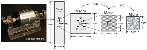
Electrospun PEUU scaffolds exhibit complex multiscale hierarchical structures. Scaffold deformation was measured at three scales defined as micro, meso, and macro. At the micro and mesoscales, the structural characteristics of fiber orientation, tortuosity, and diameter were quantified. [Color figure can be viewed in the online issue, which is available at www.interscience.wiley.com.]
Quantifying scale-dependent deformation
Rather than appearing as long, fully independently acting fibers, all fiber intersections were observed to be well adhered; allowing for rotation yet no slip. This allowed the bond points to act as natural material fiducial points, so that intersection displacements were quantified during deformation to a consistent metric to calculate scaffold microscale deformation behavior. The displacements of fiber intersection points (n > 60) were tracked between the reference and deformed configurations, using a single Lagrangian 9 node element to interpolate the 2D strain field.20,21 In the case of the macro and mesoscale strains, the deformation gradient was determined via bilinear interpolation.22 The mesoscale measurements had a characteristic length approximately 20 times larger than the microscale. Finally, macroscale strains (1 mm or larger) were dictated by the displacements of four fiducial markers on the specimen surface.
Fiber diameter, tortuosity, and orientation
SEM micrographs of the PEUU construct cross section appear to be visually consistent in architecture through the thickness of the specimen [Fig. 2(a)]. As such it is reasonable to conclude that measurements such as fiber diameter, orientation, and tortuosity [Fig. 2(b,c)] obtained from the specimen surface represent the entire fiber population reasonably well. Several image analysis techniques were used to quantify fiber diameter, orientation, and tortuosity. Fiber diameter, determined from the distance between fiber edges perpendicular to the fiber axial direction, was measured from 50 arbitrarily chosen fibers throughout the image via a custom, semiautomated image analysis algorithm implemented in MATLAB (The MathWorks, Natick MA). We also noted that increasing the sampling frequency greater than 50 fibers was not observed to significantly alter the population mean or variance.
Figure 2.

(a) Electrospun PEUU architecture visually appears to be consistent through the thickness of the specimen. From this manufacturing technique, a continuous mat is produced by successive layers of nonwoven polymer. At the mesoscale (b), PEUU fibers are seen to exhibit significant tortuosity, as highlighted in red, with this structural characteristic becoming much more prominent with increasing scale (c). Tortuosity is defined as the ratio of a given fiber’s actual length (perimeter) to its end-to-end length. [Color figure can be viewed in the online issue, which is available at www.interscience.wiley.com.]
PEUU fiber alignment was ascertained by an image analysis algorithm as presented in detail by Courtney et al.13 Briefly, a 7 × 7 pixel array or mask was applied to image subregions that were defined by the mean fiber diameter of six fibers throughout the image. Within each subregion, the gradient-weighted contribution of each pixel of the mask was calculated for each angle (−90°,−90°) to determine the dominant orientation. The orientation information from each subregion of the image was then compiled into a histogram representing the splay of the entire fiber population with 1° increments.
Lastly, fiber tortuosity, as defined as the ratio of the total fiber length (or perimeter) to the fiber end-to-end length, was quantified for approximately 150 fibers across a mosaic image created from a 3 × 3 array of SEM micrographs. The 150 fibers represented the upper limit of fibers that could be consistently visualized on the specimen surface spanning the mosaic image, which spatially measured approximately 150 μm wide by 120 μm high for each spin speed in the unstrained configuration. Incorporating nearly all visible fibers was also beneficial because it prevented the observer from inadvertently skewing the population by selection error. This process was accomplished via custom software that tracked fibers along their length in a semiautomated manner. First, the user arbitrarily defined fibers of interest that visually spanned the image to quantify fiber tortuosity and were assigned values in increments of 0.01. It should also be noted that from preliminary data (not shown), and as in our previous study,13 no observable change in fiber splay was measured between the specimen surface facing the mandrel and the exterior specimen surface. Moreover, SEM micrographs of the specimen surface were previously observed to show close agreement with subsurface images obtained via laser scanning confocal microscopy.1
Measured relation between fiber angle and tortuosity
Raw tortuosity data, which was originally measured over θ ∈ [−90°,90°] was reflected to θ ∈ [0°,90°], as justified by the observed symmetry about the preferred fiber direction (i.e., θ = 0°). To visualize these results, a 2D histogram of all data was created from the occurrences of fibers located at a particular angle (θ) and given tortuosity (T), which could then be transformed into a probability distribution P(θ,T). This approach enables us to further investigate the correlations between fiber tortuosity and orientation and describe the unique recruitment behavior of the scaffolds under large deformations. Because of the cumbersome nature of obtaining additional experimental data (see earlier for tortuosity measurement methods) to further populate a complete probability distribution, a continuous approximation was necessary. From preliminary inspections of the experimental 2D histogram data from each scaffold, large gradients were observed between neighboring points prohibiting the use of conventional surface-fitting techniques. An interpolation approach was formulated through the use of an unstructured grid that could be tailored to sufficiently capture the features of the discrete tortuosity distribution while eliminating the need for higher order element equations. As such, the data was binned into angle increments of 15° such that one-dimensional tortuosity distributions for constant θ could be fit in a piecewise manner. Each interval of discrete data was fit by a finite-element-based numerical approximation using multiple 1D quadratic elements. It was determined that a minimum of three 1D elements were necessary to adequately capture the T distributions for each value of constant θ. A resulting continuous surface, P(θ,T) was then created by linearly interpolating probability values between each of the 15° increments. Lastly, the volume bound by the created surface from each mandrel speed scaffold was normalized to have a unit volume.
RESULTS
P(θ,T)
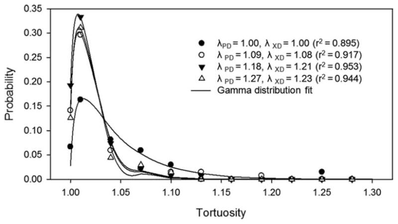
The surface-fitting method outlined earlier was capable of capturing the behavior of the raw data well (r2 = 0.967 or greater) for all mandrel velocity constructs. Although changes in the surface created by the P(θ,T) data for each spin speed were subtle, several interesting trends were observed (Fig. 3). For all scaffolds, a primary probability peak was observed about the origin or preferred fiber direction. As construct fiber alignment increased, the breadth of this peak increased and the height of the peak decreased accordingly (Fig. 3). This indicated a shift in the population from fibers with relatively low tortuosity levels at low spin speeds to increased tortuosity levels at all angles. In particular, the probability of observing a fiber of very high tortuosity increased with mandrel velocity. For the 1.5 and 3.0 m/s constructs, which are known to exhibit minor differences in fiber splay,13 very similar P(θ,T) were observed. This result was also indicative of our ability to consistently and repeatedly produce PEUU constructs of similar architecture. Interestingly, secondary probability peaks were always observed in the XD (see the symbol “*” in Fig. 3), whereas in the PD, a peak was seen to evolve with increasing mandrel velocity.
Figure 3.

The complex relation between fiber tortuosity and its angle of orientation was observed to be a function of increased mandrel velocity. All scaffolds exhibited a primary probability peak about the origin (PD). As mandrel velocity increased, the height of the peak decreased while its breadth increased, indicating a shift in the population from fibers generally exhibiting low tortuosity levels at low spin speeds to increased tortuosity levels at all angles. Interestingly, a secondary probability peak was seen to develop in the PD with low to moderate tortuosity levels as mandrel velocity increased (denoted by the arrow), whereas the XP always exhibited a subpopulation of fibers with relatively low tortuosity values (indicated by “*”). Also, note the consistency between the surfaces of the 1.5 and 3.0 m/s scaffolds which exhibit marginal levels of fiber alignment compared to the aligned scaffolds of the 4.5 and 9.0 m/s mandrel velocities. [Color figure can be viewed in the online issue, which is available at www.interscience.wiley.com.]
Although counterintuitive (see Discussion section), increased levels of tortuosity were observed in the specimens produced at higher spin speeds. For instance, the fiber tortuosity distribution across all angles in the highly aligned 9.0 m/s specimen peaked at a tortuosity value of approximately 1.3 and was centered about the preferred fiber direction. Conversely, 1.5 m/s mandrel velocity specimens produced with no-measurable fiber alignment exhibited a rather constant tortuosity distribution with no discernable peaks and an average tortuosity value of 1.08. It should also be noted that a higher density of fibers was observed in the PD with increasing alignment as anticipated.
Microstructural response to biaxial deformation
As expected, the equibiaxial deformation states used in this study resulted in no change in the orientation of the fiber population. A number of individual fibers were observed to rotate or change their direction of orientation; however, as a population these effects canceled such that no net change was observed. Although the effects of equibiaxial deformation on fiber orientation were not surprising, the fiber tortuosity response proved to be rather interesting and complex. As equibiaxial deformation increased, fiber tortuosity was reduced in both the PD and XD but not extinguished completely (Fig. 4). The PEUU fiber intersections appear to be quite secure and while allowing relatively free rotation about the point of intersection, fiber slippage or translation was inhibited, limiting fiber straightening and resulting in a residual level of tortuosity.
Figure 4.
When fit by a simple gamma distribution, the tortuosity probability distribution of a representative specimen (9.0 m/s) shifts toward the left with scaffold deformation, indicating fiber straightening. This phenomenon is similar to the extinction of collagen crimp in native collagenous tissues, however, after initial deformation, little change in tortuosity distribution is observed. This phenomenon is a result of secure fiber interconnections preventing complete fiber straightening.
The multiscale deformation behavior for each specimen spin demonstrated that, as the scaffold was stretched to increasing levels, the computed stretch value ranges increased accordingly at each scale. However, we observed that that there are some discrepancies in deformation levels across the three scales defined in this study (Fig. 5). This can be seen in Figure 5 which presents mean and standard error values for the mesoscale and the mean and standard deviation of the microscale deformation as a function of the mean macrostretch for the 4.5 m/s scaffold. As plotted, the superimposed line represents unity at the macroscale, and data that fall along this line show agreement between its respective scale and the macrodeformation observed. The XD results show good agreement while the macroscale deformation in the PD underestimates the deformations seen at the meso and microscales. Raw measured values are also presented to show the actual distribution of the data, so as to avoid any assumptions of their actual distribution. At the microscale, a very heterogeneous deformation response is observed throughout the image plane (Fig. 6) with large changes in deformation. At the mesoscale, substantially less variation is observed in the deformation response but the interpolated ranges in deformation remain relatively large. It is not until the macroscale, on the order of 1000–3000 μm, that homogeneous deformation behavior was observed.
Figure 5.

Observed multiscale deformation behavior. Presented are the mean and standard error (meso) or standard deviation (micro) values as a function of mean macroscale deformation for comparison. Raw values (open symbols) are also plotted to depict the true span of the observed deformation. When electrospun PEUU scaffolds are deformed, some discrepancies do arise between the defined scales as seen by data which diverges from unity (gray line). This is attributed to the complex, spatially variant structure which results from the electrospinning process at the microscale. As the characteristic length is increased, the measured deformation field becomes increasingly homogeneous such that a reasonably uniform response is observed at the macroscale (1–3 mm).
Figure 6.

The firmly adhered fiber intersection points provide an ideal measure of microscale deformation (left panel). By tracking the displacement of these intersections between the reference and deformed configurations, the stretch in both the PD and XD were calculated via a single Lagrangian 9 node element (right panel). In short, the stretch values in each material axis (PD and XD, respectively) are simply defined as the displacement gradient or strain plus 1. Note the heterogeneous deformation behavior exhibited at the microscale. Warm colors denote large stretch values, whereas cool colors denote regions of low stretch. [Color figure can be viewed in the online issue, which is available at www.interscience.wiley.com.]
In the unstrained state, a trend was observed wherein the PEUU fiber diameter decreased with increasing mandrel velocity during production. Furthermore, with increased deformation, a monotonic decrease in PEUU fiber diameter was measured for all specimens indicating an incompressible (or nearly incompressible) material behavior. The fiber diameter underwent statistically significant decreases in diameter at each strain level for the specimens produced with 1.5 and 4.5 m/s mandrel velocities.
DISCUSSION
Relevance of this study
Ideally, it would be possible to manufacture tissue surrogates from a scaffold precisely mimicking tissue mechanical function, containing viable cells or encourages cell migration from the host, and also serves to guide cellular processes and the arrangement of newly produced extracellular matrix. Although this technology does not currently exist, electrospun PEUU scaffolds provide a logical “next step” from current fibrous scaffold technologies for tissue engineering such as needled nonwoven biodegradable polymers23,24 or biopolymer scaffolds.25–27 Needled nonwoven scaffolds are limited in their abilities to emulate soft tissue tensile deformation behaviors because they cannot undergo fully recoverable large deformations. Biopolymer gels, while inherently exhibiting good cytocompatibility, may not functionally behave as long fiber composite materials as indicated in a recent study by Thomopoulous et al.,28 in which they were unable to satisfactorily apply a structural continuum model.29–31 This may also lend insight to their general lack of mechanical integrity rendering them unable to adequately mimic native tissues in a functional manner. Native valvular tissues, on the other hand, exhibit collagen fibers or fiber bundles spanning the leaflet that measure on the order of tens of millimeters. Electrospun scaffolds better emulate this hierarchical structural organization because the manufacturing process is basically a continuous extrusion of polymer.
The electrospun PEUU scaffolds investigated in this study exhibited complex, hierarchical architectures spanning multiple length scales (Fig. 7). These structures combine to form a complex 3D scaffold with tunable tissue-level mechanical behavior that can be remarkably similar to the biaxial mechanical response of the native PV leaflet.13 However, understanding the mechanisms by which these materials deform and behave under various loading conditions is not an elementary task. At the macroscale, the electrospun PEUU scaffold is capable of recapitulating the long, independently acting fiber response exhibited by the dense collagen network of the native PV (Fig. 7, right panel). Moreover, recent modeling attempts originally developed for dense collagenous planar tissues proved quite successful in capturing the mechanical behavior of electrospun scaffolds under biaxial modes of deformation.13
Figure 7.
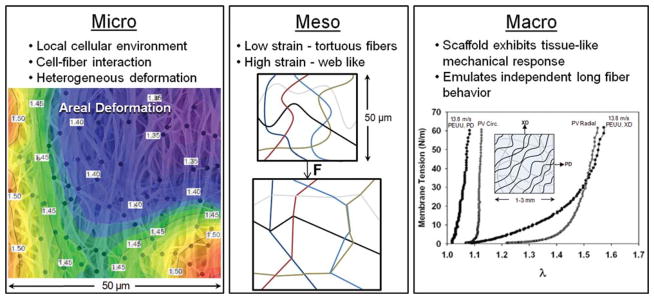
Despite exhibiting a tissue-like mechanical response at the macroscale, the scaffold exhibits vastly different micro and meso mechanical behaviors. For instance, at the microscale, a heterogeneous deformation response is observed. In addition, fibers in the unstrained configuration exhibit an undulated or tortuous morphology which transitions into a highly interconnected web-like architecture at finite strains. At the macroscale, we observe a complex 3D scaffold with tunable tissue-level mechanical behavior that can be remarkably similar to the biaxial mechanical response of the native PV leaflet (biaxial result reproduced from Courtney et al.13 with permission from Elsevier). [Color figure can be viewed in the online issue, which is available at www.interscience.wiley.com.]
However, despite the success of these initial attempts, some of the assumptions made during the formulation of the model preclude it from accurately capturing the effects of microstructural characteristics.13,30,32,33 Namely, it was assumed that the scaffold could be idealized as a planar network of independently acting fibers with the fiber strain being computed from the tensorial transformation of the global strain tensor (the affine assumption). In this and previous study,13 at the macroscale, the electrospun PEUU scaffolds deformed as long-fibrous networks. More importantly, this study has shown that both fiber tortuosity and fiber orientation are dependent upon mandrel velocity. This result clearly indicates that fiber recruitment with strain would proceed in an angle-associated manor necessitating model modifications to account for these structure-related behaviors. This finding exemplifies the need to elucidate microstructural characteristics and their functional role at the macroscale in both native and synthetically derived matrices.
Multiscale deformation behavior
Scale-dependent variations in deformation levels were observed (Fig. 5). We attributed this behavior to the complex, spatially variant structure that results from the electrospinning process (Figs. 6 and 7). It is anticipated that other regions throughout the specimen would behave in a unique manner dependent upon its local architecture at the microscale. However, as the characteristic length is increased from the heterogeneous microstructural scale to the macroscale, the scaffold deformation behavior becomes increasingly more homogeneous. Interestingly, it is at the macroscale (~1 to 3 mm) that the highly aligned electrospun PEUU behaves remarkably similar to native pulmonary valve tissue under biaxial testing regimes. This indicates that it may be possible to successfully emulate gross native tissue behavior without exactly replicating their highly complex microarchitectures.
Microscale fiber kinematics of electrospun PEUU and native collagenous tissues
In this study, we have shown that the PEUU fibers undergo a recruitment process with deformation wherein the unstrained configuration, characterized by a population of tortuous fibers, transitions into a highly interconnected web-like architecture at finite deformation levels (Fig. 7, center panel). Despite recapitulating the gross mechanical response, electrospun PEUU microstructure and its resulting behaviors are different than the bimodal crimp reduction and fiber compaction mechanisms observed in the native valve leaflet in response to increasing transvalvular pressure.34 Instead, the microstructure of the PEUU scaffold is largely mediated by firmly adhered fiber intersections and fiber straightening effects, which can induce a different deformation response for encapsulated cells during scaffold deformation.1
Effects of fiber morphology and kinematics on scaffold mechanical behavior
With increased mandrel velocity, increased levels of fiber alignment are obtained along with increased tortuosity. Increased mandrel velocity would be expected to shift the fibers toward the preferred direction as observed. However, it was also observed that fibers oriented in the preferred direction exhibited increased tortuosity. Hypothetically, the spinning mandrel would pull on the newly polymerized fibers as they are deposited. This is a counterintuitive phenomenon as one might anticipate tortuosity to be decreased in the preferred direction as a result of the potential for increased fiber tension as the mandrel spins.
From a functional standpoint, this phenomenon may contribute to the highly nonlinear anisotropic behavior exhibited during biaxial deformation. Specifically, the presence of fibers with varying tortuosity indicates an intricate directionally dependent fiber recruitment process during deformation. When the biaxial mechanical response (equitension, previously presented by Courtney et al.13) in the PD and XD are normalized, we see little difference in the shapes of the PD behavior with increased spin speed while the XD shows a trend to become more concave or nonlinear (Fig. 8). With increased mandrel velocity, we see an increased density of fibers about the PD with a range of tortuosity levels which results in little change in the PD response. Fiber tortuosity, though not ubiquitous in electrospinning literature, can visually be observed when segmented polyurethane materials are used.35,36 The true mechanism for the production of tortuous fibers, though interesting, is beyond the scope of this study but may be a result of a “whipping” instability in the polymer jet during deposition causing the jet to bend and stretch.37–39
Figure 8.

By normalizing the PD and XD equibiaxial tension behavior (adapted from Courtney et al.13), the characteristic shape of the curves can be directly compared. As mandrel velocity is increased, the characteristic shape of the normalized response becomes more concave or nonlinear. There is little change in the shape of the tension-stretch curves in the PD, while fiber alignment increases in the XD, the response becomes more nonlinear. This phenomenon appears to be mediated by both fiber rotation effects as well as the increased fiber tortuosity observed in the aligned scaffolds.
The anisotropic behavior of native valve leaflets has been shown to be a result of rotational fiber kinematics under biaxial modes of deformation.21,32 In addition, electrospun PEUU constructs have been shown to follow affine fiber transformations from a global perspective and can be described in a manner similar to collagenous scaffolds.19 Interestingly, some fibers were observed to rotate or change their direction of orientation during deformation, while as a population, no net change was measured. This is likely an additional manifestation of the local heterogeneity that exists at the microscale. Although the affine transformation was valid at the macroscale, it is likely that PEUU fiber translation is limited by the presence of secure interconnections between fibers. Johnson et al.40 presented a similar hypothesis for reduced fiber mobility in electrospun polymers exhibiting “point bonding.” In short, polymer sintering was used on electrospun poly(ε-caprolactone) scaffold to invoke definite point bonds between fibers. Therefore, the presence of increasingly tortuous fibers in the XD and their recruitment with scaffold strain may work in conjunction with fiber kinematics to produce the anisotropic biaxial mechanical behavior, which so closely mimics native leaflet tissue. Attempting to delineate the individual contributions of fiber tortuosity and kinematics to the constructs, mechanical behavior would be quite cumbersome and better lends itself to the development of a numerical framework to explore this unique, interrelated phenomenon.
Limitations
It should be noted that this study was limited to the investigation of one specimen per spin speed. However, we have shown that scaffold structure is well preserved across the entire specimen or from multiple specimens produced from a single production batch. For example, Courtney et al.13 showed that fiber splay quantified from several regions across the specimen show very close agreement. Furthermore, there is close agreement between structural characterization (fiber splay) of both the specimen surface facing the mandrel and the exposed surface. Biaxial mechanical characterization of multiple constructs at each of the mandrel velocities investigated here showed close agreement because of consistent architectures.
In this study, it has been shown that the measured θ-T-P(θ,T) profiles for the 1.5 and 3.0 m/s constructs, which exhibit comparable effective fiber properties, were very similar upon visual inspection. As such, we are confident that any interspecimen variation that may exist is beyond our ability to measure and thus would have inconsequential effects on scaffold kinematics and mechanical behavior. In a similar light, it is difficult to speculate what affects the inclusion of specimens from successive batches of scaffolds produced under the same or similar manufacturing conditions may have on our results. Although the electrospinning process is done in a controlled manner, it is not an exact process but relies heavily on a multitude of manufacturing parameters working in unison to produce a given scaffold.
SUMMARY AND FUTURE DIRECTIONS
The purpose of this study was not to develop assessment techniques for the evaluation of electrospun scaffolds but rather to elucidate fundamental electrospun fabric microstructure, investigate the functional relevance of the observed microstructure, and finally to lay the basis for future modeling efforts. Specifically, we were able to determine that the macroscale (1–3 mm) is most appropriate for modeling efforts as a homogeneous deformation behavior is attained. As mentioned earlier, the modeling efforts previously presented by Courtney et al. proved successful in capturing the biaxial mechanical behavior of electrospun PEUU scaffolds with varying levels of anisotropy. The predictive ability of this approach can be improved by incorporating additional means to describe the scaffold’s microarchitectural behaviors. For instance, incorporating a recruitment function describing fiber tortuosity behavior as a function of scaffold strain will better emulate true fiber behavior. Moreover, this recruitment behavior can be derived directly from the θ-T-P(θ,T) distributions developed in this study. This improved model will enable us to further explore the importance that PEUU tortuosity has on gross scaffold function.
Practical uses of such a model include guiding scaffold design for tissue- or cell-specific applications and optimizing in vitro conditioning regimes to produce tissue constructs for implantation. Furthermore, the incorporation of microstructural morphologies and behaviors when modeling tissue level function can guide scaffold production methods and the development of construct characterization tools. For example, with a fundamental understanding of scaffold microstructure, it would be possible to simulate the effects of altered fiber morphologies (i.e., fiber orientation, tortuosity, fiber-to-fiber connectivity) on macroscale material behavior in a concise and rational manner. Furthermore, a modeling framework would be valuable in isolating fiber morphologies of keen interest which in turn will streamline to the process of developing scaffold characterization tools (once it is know what characteristics to measure) or new production techniques to obtain the desired micromorphologies. Finally, by developing a structural constitutive model capable of incorporating scaffold fiber microarchitectures (fiber orientation, fiber tortuosity), we hope to gain additional insight into PEUU scaffold micromechanics and be able to relate tissue strains with local cellular deformations. Whether cells are physically seeded or are present through natural infiltration, it is beneficial to understand and potentially control changes in the local fiber network during global deformations to manage the cell population response to mechanical stimuli.
Acknowledgments
The authors thank Todd Courtney for his contributions in acquiring experimental data and John Stankus for providing the electrospun materials.
Contract grant sponsor: NIH; contract grant numbers: R01s HL68816, R01s HL69368
Contract grant sponsor: NIH-NHLBI; contract grant number: T32-HL76124
References
- 1.Stella JA, Liao J, Hong Y, David Merryman W, Wagner WR, Sacks MS. Tissue-to-cellular level deformation coupling in cell micro-integrated elastomeric scaffolds. Biomaterials. 2008;29:3228–3236. doi: 10.1016/j.biomaterials.2008.04.029. [DOI] [PMC free article] [PubMed] [Google Scholar]
- 2.Wang JH, Thampatty BP. An introductory review of cell mechanobiology. Biomech Model Mechanobiol. 2006;5:1–16. doi: 10.1007/s10237-005-0012-z. [DOI] [PubMed] [Google Scholar]
- 3.Dahl KN, Ribeiro AJ, Lammerding J. Nuclear shape, mechanics, and mechanotransduction. Circ Res. 2008;102:1307–1318. doi: 10.1161/CIRCRESAHA.108.173989. [DOI] [PMC free article] [PubMed] [Google Scholar]
- 4.Merryman WD, Huang HY, Schoen FJ, Sacks MS. The effects of cellular contraction on aortic valve leaflet flexural stiffness. J Biomech. 2006;39:88–96. doi: 10.1016/j.jbiomech.2004.11.008. [DOI] [PubMed] [Google Scholar]
- 5.Yanagisawa M, Suzuki N, Mitsui N, Koyama Y, Otsuka K, Shimizu N. Effects of compressive force on the differentiation of pluripotent mesenchymal cells. Life Sci. 2007;81:405–412. doi: 10.1016/j.lfs.2007.06.004. [DOI] [PubMed] [Google Scholar]
- 6.Terraciano V, Hwang N, Moroni L, Park HB, Zhang Z, Mizrahi J, Seliktar D, Elisseeff J. Differential response of adult and embryonic mesenchymal progenitor cells to mechanical compression in hydrogels. Stem Cells. 2007;25:2730–2738. doi: 10.1634/stemcells.2007-0228. [DOI] [PubMed] [Google Scholar]
- 7.Song G, Ju Y, Shen X, Luo Q, Shi Y, Qin J. Mechanical stretch promotes proliferation of rat bone marrow mesenchymal stem cells. Colloids Surf B Biointerfaces. 2007;58:271–277. doi: 10.1016/j.colsurfb.2007.04.001. [DOI] [PubMed] [Google Scholar]
- 8.Engelmayr GC, Jr, Sacks MS. Prediction of extracellular matrix stiffness in engineered heart valve tissues based on nonwoven scaffolds. Biomech Model Mechanobiol. 2008;7:309–321. doi: 10.1007/s10237-007-0102-1. [DOI] [PubMed] [Google Scholar]
- 9.Roeder BA, Kokini K, Robinson JP, Voytik-Harbin SL. Local, three-dimensional strain measurements within largely deformed extracellular matrix constructs. J Biomech Eng. 2004;126:699–708. doi: 10.1115/1.1824127. [DOI] [PubMed] [Google Scholar]
- 10.Guilak F, Ratcliffe A, Mow VC. Chondrocyte deformation and local tissue strain in articular cartilage: A confocal microscopy study. J Orthop Res. 1995;13:410–421. doi: 10.1002/jor.1100130315. [DOI] [PubMed] [Google Scholar]
- 11.Ingber DE. Mechanobiology and diseases of mechanotransduction. Ann Med. 2003;35:564–577. doi: 10.1080/07853890310016333. [DOI] [PubMed] [Google Scholar]
- 12.Lee DA, Knight MM. Mechanical loading of chondrocytes embedded in 3D constructs: In vitro methods for assessment of morphological and metabolic response to compressive strain. Methods Mol Med. 2004;100:307–324. doi: 10.1385/1-59259-810-2:307. [DOI] [PubMed] [Google Scholar]
- 13.Courtney T, Sacks MS, Stankus J, Guan J, Wagner WR. Design and analysis of tissue engineering scaffolds that mimic soft tissue mechanical anisotropy. Biomaterials. 2006;27:3631–3638. doi: 10.1016/j.biomaterials.2006.02.024. [DOI] [PubMed] [Google Scholar]
- 14.Nerurkar NL, Elliott DM, Mauck RL. Mechanics of oriented electrospun nanofibrous scaffolds for annulus fibrosus tissue engineering. J Orthop Res. 2007;25:1018–1028. doi: 10.1002/jor.20384. [DOI] [PubMed] [Google Scholar]
- 15.Yoshimoto H, Shin YM, Terai H, Vacanti JP. A biodegradable nanofiber scaffold by electrospinning and its potential for bone tissue engineering. Biomaterials. 2003;24:2077–2082. doi: 10.1016/s0142-9612(02)00635-x. [DOI] [PubMed] [Google Scholar]
- 16.Stankus JJ, Guan J, Wagner WR. Fabrication of biodegradable elastomeric scaffolds with sub-micron morphologies. J Biomed Mater Res A. 2004;70:603–614. doi: 10.1002/jbm.a.30122. [DOI] [PMC free article] [PubMed] [Google Scholar]
- 17.Sacks MS. Biaxial mechanical evaluation of planar biological materials. J Elasticity. 2000;61:199–246. [Google Scholar]
- 18.Billiar KL, Sacks MS. A method to quantify the fiber kinematics of planar tissues under biaxial stretch. J Biomech. 1997;30:753–756. doi: 10.1016/s0021-9290(97)00019-5. [DOI] [PubMed] [Google Scholar]
- 19.Gilbert TW, Sacks MS, Grashow JS, Woo SL, Badylak SF, Chancellor MB. Fiber kinematics of small intestinal submucosa under biaxial and uniaxial stretch. J Biomech Eng. 2006;128:890–898. doi: 10.1115/1.2354200. [DOI] [PubMed] [Google Scholar]
- 20.Bathe KJ. Finite Elements Procedures in Engineering Analysis. Englewood Cliffs, NJ: Prentice-Hall; 1982. [Google Scholar]
- 21.Billiar KL, Sacks MS. Biaxial mechanical properties of the natural and glutaraldehyde treated aortic valve cusp. I. Experimental results. J Biomech Eng. 2000;122:23–30. doi: 10.1115/1.429624. [DOI] [PubMed] [Google Scholar]
- 22.Spencer AJM. Continuum Mechanics. New York: Longman Scientific and Technical; 1980. p. 183. [Google Scholar]
- 23.Freed LE, Vunjak-Novakovic G, Biron RJ, Eagles DB, Lesnoy DC, Barlow SK, Langer R. Biodegradable polymer scaffolds for tissue engineering. Nat Biotechnol. 1994;12:689–693. doi: 10.1038/nbt0794-689. [DOI] [PubMed] [Google Scholar]
- 24.Engelmayr GC, Jr, Rabkin E, Sutherland FW, Schoen FJ, Mayer JE, Jr, Sacks MS. The independent role of cyclic flexure in the early in vitro development of an engineered heart valve tissue. Biomaterials. 2005;26:175–187. doi: 10.1016/j.biomaterials.2004.02.035. [DOI] [PubMed] [Google Scholar]
- 25.Neidert MR, Tranquillo RT. Tissue-engineered valves with commissural alignment. Tissue Eng. 2006;12:891–903. doi: 10.1089/ten.2006.12.891. [DOI] [PubMed] [Google Scholar]
- 26.Robinson PS, Johnson SL, Evans MC, Barocas VH, Tranquillo RT. Functional tissue-engineered valves from cell-remodeled fibrin with commissural alignment of cell-produced collagen. Tissue Eng. 2008;14:83–95. doi: 10.1089/ten.a.2007.0148. [DOI] [PubMed] [Google Scholar]
- 27.Thomopoulos S, Fomovsky GM, Holmes JW. The development of structural and mechanical anisotropy in fibroblast populated collagen gels. J Biomech Eng. 2005;127:742–750. doi: 10.1115/1.1992525. [DOI] [PubMed] [Google Scholar]
- 28.Thomopoulos S, Fomovsky, Gregory M, Chandran Preethi L, Holmes, Jeffry W. Collagen fiber alignment does not explain mechanical anisotropy in fibroblasr populated collagen gels. J Biomech Eng. 2007;129:642–650. doi: 10.1115/1.2768104. [DOI] [PubMed] [Google Scholar]
- 29.Lanir Y. The rheological behavior of the skin: Experimental results and a structural model. Biorheology. 1979;16:191–202. doi: 10.3233/bir-1979-16308. [DOI] [PubMed] [Google Scholar]
- 30.Sacks MS. Incorporation of experimentally-derived fiber orientation into a structural constitutive model for planar collagenous tissues. J Biomech Eng. 2003;125:280–287. doi: 10.1115/1.1544508. [DOI] [PubMed] [Google Scholar]
- 31.Sacks MS. A structural constitutive model for chemically treated planar tissues under biaxial loading. Comput Mech. 2000;26:243–249. [Google Scholar]
- 32.Billiar KL, Sacks MS. Biaxial mechanical properties of the native and glutaraldehyde-treated aortic valve cusp. II. A structural constitutive model. J Biomech Eng. 2000;122:327–335. doi: 10.1115/1.1287158. [DOI] [PubMed] [Google Scholar]
- 33.Lanir Y. Constitutive equations for fibrous connective tissues. J Biomech. 1983;16:1–12. doi: 10.1016/0021-9290(83)90041-6. [DOI] [PubMed] [Google Scholar]
- 34.Huang HY, Liao J, Sacks MS. In-situ deformation of the aortic valve interstitial cell nucleus under diastolic loading. J Biomech Eng. 2007;129:880–889. doi: 10.1115/1.2801670. [DOI] [PubMed] [Google Scholar]
- 35.Stylianopoulos A, Bashur CA, Goldstein AS, Guelcher SA, Barocas VH. Computational predictions of the tensile properties of electrospun fibre meshes: Effect of fibre diameter and fibre orientation. J Mech Behav Biomed Mater. 2008;1:326–335. doi: 10.1016/j.jmbbm.2008.01.003. [DOI] [PMC free article] [PubMed] [Google Scholar]
- 36.Kidoaki S, Kwon IK, Matsuda T. Structural features and mechanical properties of in situ-bonded meshes of segmented polyurethane electrospun from mixed solvents. J Biomed Mater Res B Appl Biomater. 2006;76:219–229. doi: 10.1002/jbm.b.30336. [DOI] [PubMed] [Google Scholar]
- 37.Shin YM, Hohman MM, Brenner MP, Rutledge GC. Experimental characterization of electrospinning: the electrically forced jet and instabilities. Polymer. 2001;42:9955–9967. [Google Scholar]
- 38.Shin YM, Hohman MM, Brenner MP, Rutledge GC. Electro-spinning: A whipping jet generates submicron polymer fibers. Appl Phys J. 2001;78:1149–1151. [Google Scholar]
- 39.Hohman MM, Shin YM, Rutledge GC, Brenner MP. Electro-spinning and electrically forced jets. I. Stability theory. Phys Fluids. 2001;13:2201–2220. [Google Scholar]
- 40.Johnson J, Ghosh A, Lannutti J. Microstructure-property relationships in a tissue-engineering scaffold. J Appl Polym Sci. 2007;104:2919–2927. [Google Scholar]