

Abstract
We report a novel modification of silicone elastomer, polydimethylsiloxane (PDMS) with a polymer graft that allows interfacial bonding between elastomer and glass substrate to be performed without exposure of said substrate to harsh treatment conditions like oxygen plasma. Organic molecules can thus be patterned within microfluidic channels and still remain functional post-bonding. In addition, after polymer grafting the PDMS can be stored in a desiccator for at least 40 days, and activated upon exposure to acidic buffer for bonding. The bonded devices remain fully bonded in excess of 80 psi driving pressure, with no signs of compromise to the bond integrity. Finally, we demonstrate the compatibility of our method with biological molecules using a proof-of-concept DNA sensing device, in which fluorescently-labelled DNA targets are successfully captured by a patterned probe in a device sealed using our method, while the pattern on a plasma-treated device was completely destroyed. Therefore, this method provides a much-needed alternative bonding process for incorporation of biological molecules in microfluidic devices.
1. Introduction
Microfluidics has in recent years been an increasingly important technology for diagnostics, molecular biology, chemical reactions, and other biomedical applications.1 Its strength stems in part from the ability to exert spatio-temporal control to an extent nearly impossible using traditional techniques, thus enabling timely introduction of reagents.2 Researchers have also found that the small length scales affect the physics and chemistry of many reactions and processes,3 thereby potentially extending the capabilities of existing materials New diagnostic assays have also been developed, taking advantage of the small amounts of reagents needed to carry out various reactions.4, 5
Polydimethylsiloxane (PDMS), an elastomeric polymer, has contributed greatly to the accessibility of microfluidic platforms, by allowing rapid prototyping, repeated mold casting in as little as one step, and also mechanical and chemical stability that are suitable for a broad range of applications.6 In typical microfluidic devices, PDMS casted on a microfabricated SU-8 mold is peeled off upon curing and bonded onto a glass substrate to create sealed chambers or microchannels. There is often a need to functionalize surfaces of these devices with biological molecules in order to confer diagnostic or biosensing capabilities. These biomolecules can be introduced after device bonding by flowing solutions of desired molecules into the channels, though this only allows uniform, homogeneous modification of channel walls.7 In order to create patterned structures of biological materials, which are essential in biosensing and tissue engineering applications, device bonding has to be performed after patterning.
The primary method for PDMS/glass bonding uses oxygen-plasma treatment, which generates Si-OH silanol groups that undergo condensation reactions to yield Si-O-Si bonds that have a burst pressure of 24 to 74 psi, depending on the protocol used.8, 9
Despite the ease of bonding and the relatively high bonding strengths, oxygen-plasma treatment has two significant disadvantages. Firstly, plasma-treated surfaces remain chemically reactive for only up to ten minutes after treatment. Thus, end-users who want to incorporate soft materials like membranes, tissues and macromolecules into micro-devices suffer from limited or insufficient time to accomplish such tasks. Secondly, the harsh conditions associated to oxygen plasma can easily damage organic molecules. Thus, oxygen plasma treatment is ill-suited to applications wherein organic molecules have to be introduced prior to sealing the device. Getting around these limitations often results in complicated microfluidic device fabrication, which can make scaling-up difficult,10 or the use of reversible bonds with vacuum-driven flow, which limit the driving pressures to one atmosphere.4, 11
In recent years alternative bonding methods have been explored. Corona-triggered PDMS bonding function in a similar way to oxygen plasma, but is much cheaper to operate.12 However, the activation is also short-lived; low throughput and non-uniformity of treated surface further limits the method’s utility. Adhesive-based methods have also been proposed, variously using PDMS, SU-8 photoresist, and other epoxy-based glues to bond the two surfaces. However, the thickness of these viscous polymers are difficult to control, leading to the small amounts of uncured glue that enter the channels, which is often enough to clog the devices or otherwise alter the dimensions of the microchannels.13 Delamination of the adhesive layer is also a significant challenge.13 These challenges can in turn be circumvented by modification of the glass/PDMS or PDMS/PDMS surfaces with molecular-thickness complementary molecules, utilizing amine-epoxy,14-16 amine-silanol,17 and amine-aldehyde18 chemistries that react to form strong covalent bonds. However, in some cases, these molecules are introduced to both bonding surfaces using processes that utilize oxygen plasma which can damage the biomolecules pre-patterned on the surfaces.14-17 Alternatively, chemical vapour deposition (CVD) has been demonstrated to be able to achieve thin, conformal layers that can achieve high bond strength.14, 18, 19 However, since the material is uniformly deposited on the whole surface, pre-patterned biomolecules will be obscured by the deposited material. Post-CVD introduction of organic or biomolecules, on the other hand, requires the presence of specific functional groups that can be conjugated to the deposited polymer, thereby limiting the types of molecules that can be introduced.18, 20
In this paper we introduce a novel bonding strategy based on alkoxysilane chemistry. Specifically, 3-methacryloyl-propyltrimethoxysilane or bind-silane, commonly used for covalently bonding polyacrylamide gels to treated glass plates,21, 22 is polymerized using free-radical polymerization, and grafted onto the PDMS surface in an easily scalable reaction scheme, modified from reported protocols.23, 24 The grafted polymer remains stable for at least 40 days in a desiccator until activated by hydrolysis, and can then be bonded to unmodified polished water-white low-iron soda-lime glass, regular soda-lime glass and silicon wafer native oxide layer,25, 26 in a condensation reaction that yields new Si-O-Si siloxane bonds. The ability to use unmodified substrates is critically important, as this now allows devices incorporating patterned structures that will not survive the plasma treatment to be fabricated. By eliminating any modification step to the glass substrate, different conjugation chemistries can be used to introduce organic molecules to the device through well-established organosilanes coupling agents.27 The compatibility of our method with patterned organic molecules is demonstrated with a DNA sensing device. Bonded devices attain full strength of greater than 80 psi after 4 to 16 hours, depending on the treatment conditions, and remain fully bonded after 1 year, requiring no special storage conditions.
2. Experimental Section
2.1 Materials
Soda-lime glass (Ted Pella Inc.), water-white glass coverslip (Fisherfinest Premium Glass Coverslips) are used as received, Sylgard 184® PDMS elastomer is purchased from Ellsworth Adhesives. SU-8 photoresists are procured from Microchem Corp., and biotin-modified bovine serum albumin (biotin-BSA, Sigma-Aldrich) is dissolved in Millipore-purified water to a concentration of 1 mg/mL. Complementary DNA oligonucleotides with KRAS-targeting sequences, 5’-AATATAAACTTGTGGTAGTTGGAGCTGATGGCGTAGGC AAGAGTG-biotin-3’, and 5’-GCTCCAACTACCACAAG-Cy5-3’, modified with biotin and Cy5, respectively were purchased from Integrated DNA Technologies. All other chemicals used are purchased from Sigma-Aldrich and used without further purification.
2.2 Surface TMS Modification
PDMS devices are fabricated by pouring uncured PDMS (10:1 base-curing agent ratio) using SU-8 3050 and 2000.5 molds. The PDMS is cured at 80 °C for 1 hour before peeling off the mold. Oxygen plasma treatment of the PDMS surfaces is accomplished at 150 W, 400 mTorr oxygen pressure for 30 seconds using a plasma asher (Model PE II-A, Technics West Inc.) The treated PDMS devices are then immersed in a 5% w/v solution of 3-methacryloylpropyltrimethoxysilane (MAP-TMS, Sigma-Aldrich) in acetone for 30 minutes, followed by rinsing with acetone and water, and finally baked at 80 °C for 4 hours to remove acetone from the PDMS matrix. This MAP-TMS modification step introduces C=C double bonds onto the surface of the device for grafting purposes.
2.3 Polymerization – ‘Grafting-to’ and ‘Grafting-from’
2.3.1 ‘Grafting-to’ Polymerization
In ‘grafting-to’ polymerizations, MAP-TMS-modified PDMS devices are placed in a flask with MAP-TMS (20% in methanol), benzyl alcohol (0.5 wt%), and benzophenone (16.8 mM), which is then irradiated with a UV spotlight (100 W, 20 mW/cm2 at 365 nm, Ted Pella Inc.) for 2 hours after undergoing three freeze-pump-thaw cycles using liquid nitrogen (Scheme 1A, top). Vigorous stirring is used to ensure uniform exposure of the devices to the UV light. The devices are then removed from the flask, rinsed with methanol and dried with nitrogen gun before being stored in a desiccator.
Scheme 1.
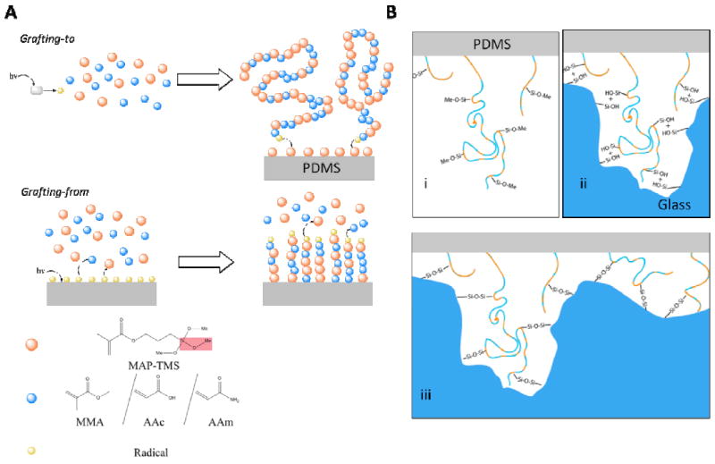
A) Grafting of the polymer is by means of ‘grafting-to’ (top) or ‘grafting-from’ (bottom) reactions. In the former, a photoinitiator (benzophenone, grey rectangle) is activated using a 365 nm UV lamp, generating a radical (yellow) in solution that propagates the polymerization with the dissolved MAP-TMS (orange) or co-polymer, namely methyl methacrylate (MMA), acrylate (AAc), or acrylamide (AAm), (blue). The still-propagating polymer is then grafted onto the MAP-TMS-modified PDMS by reacting with the C=C double bonds on the surface. In ‘grafting-from’ reactions, MAP-TMS-modified PDMS is irradiated with germicidal UV lamp to generate radicals on the elastomer surface. The radicals then propagate a free radical polymerization reaction by first attacking the surface-bound MAP-TMS, followed by the incorporation of the dissolved monomers into the growing polymer chain. The red box in the legend highlights the methoxysilane group, which is the functional unit in bond formation. B) The grafted polymer contains multiple methoxysilane groups (Si-O-Methyl, B. i) which undergo hydrolysis reactions to generate silanols groups (B. ii). These reactive hydroxyls then react with the Si-OH found on glass in a condensation reaction to form covalent Si-O-Si siloxane linkages (B. iii), which is the same reaction in oxygen plasma bonding. The undulation on the glass surface in the figure (B. ii, iii) represents the nanoscale unevenness of the material. The flexibility of our polymer allows it to access the silanols in these nanoscale pits that are inaccessible to non-polymeric silanols in traditional oxygen plasma-treated PDMS (Section 3.2, Supplementary Figure 5). The corresponding unevenness on the PDMS is omitted for clarity.
2.3.2 ‘Grafting-from’ Polymerization
MAP-TMS-modified PDMS devices are placed in a flask with MAP-TMS (10% v/v in methanol), and NaIO4 (4mM) as oxygen scavengers, and irradiated using a germicidal UV light source (5 mW/cm2 at 253 nm, 40 μW/cm2 at 365 nm, Baker Co.) for 18 hours (Scheme 1A, bottom). The reaction is otherwise identical to the ‘grafting-to’ reactions. Acrylic acid, acrylamide, and methyl methacrylate are also used as co-polymers at various ratios, while maintaining total monomer molar concentration. Polymer-modified PDMS are stored in a vacuum desiccator until needed.
2.4 ATR-FTIR Characterization of Modified Surfaces
Polymerization on the PDMS devices is characterized by attenuated total reflectance Fourier transform infrared spectroscopy (ATR-FTIR) using a Bruker Vector-22 FT-IR spectrometer with an ATR accessory, performing 64 scans at 4.0 cm-1 resolution.
2.5 PDMS-substrate Bonding Protocol and Strength Test
The polymer-grafted PDMS devices are activated by placing in a pH 4, 30 mM sodium acetate buffer for one hour. The PDMS is then rinsed with DI water and placed onto the substrate, before placing in the oven at 80 °C with a 200 g weight on top to prevent warping and loss of contact with the underlying substrate. After baking for 2 to 16 hours, the devices are removed from the oven and tested. Bonding using oxygen plasma was performed at 30 W, in a 400 mTorr oxygen environment with 1 minute exposure, followed by 4-hour baking at 80 °C.
Simple PDMS devices with a wheel-and-spoke design (Fig. 2A) are fabricated. The radial pattern is chosen to resemble microchannel spatial density in a typical microfluidic device, as well as to ensure even distribution of pressure across the chip. The radial channels are blind-ended (i.e. one inlet and no outlets) to exert uniform pressure across the entire pattern, and circumscribed by a moat (orange channels, Fig. 2A) that will fill up when the bonding fails and leakage occurs from the central channels (green channels). Since PDMS is permeable to air, water is loaded into the central channels at 8 psi until all the air is purged from the channels to ensure accurate measurement of the burst pressure. Pressure is then ramped up in 5 psi increments, with a 15-second interval between pressures to allow any damage to manifest. Upon reaching 80 psi, the device is left pressurized for 1 minute, and then actuated 5 times by turning the pressure on and off to ascertain bond integrity.
Fig. 2.
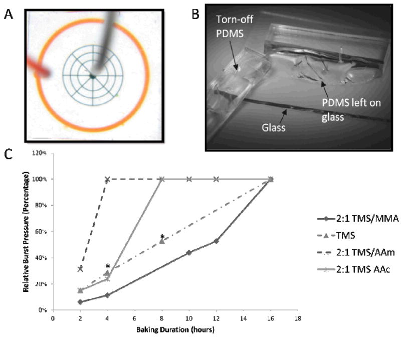
A.) A wheel-and-spoke radial design is used to represent an archetypical microfluidic device, with 50-micron wide and 100-micron tall channels (green). Water is loaded in the middle and pressurized at 8 psi to allow air to permeate through the PDMS before ramping up the pressure. The outer moat (orange) serves to collect the solution when the bonding fails. B.) Upon successful bonding, the PDMS cannot be peeled off the glass without tearing, suggesting that the bonding strength is at least on the order of the PDMS bulk strength of around 2 MPa, or 145 psi. C.) Burst pressures of devices bonded on glass at different bonding times. The relative burst pressure is normalized against 80 psi, which is the pressure at which a device is deemed fully bonded if no signs of interface failure is observed. Bonding time depends on the type of co-polymer used in the polymerization. In particular, introduction of the hydrophilic co-polymers like AAc and AAm yielded shorter bonding time, suggesting that hydrolysis may be rate-limiting. Devices marked with asterisks (*) failed locally, indicating uneven bonding. We attributed this to self-condensation of silanols, which is prevalent in MAP-TMS-only devices due to the absence of copolymers that also serve as spacers. The rest of the interface remains tightly bound.
2.6 Comparison of Grafting Method and Substrate-Copolymer Combination
PDMS grafted with MAP-TMS and acrylate or acrylamide copolymers grafted using either ‘grafting-to’ or ‘grafting-from’ approach are activated and bonded as described in Section 2.5 to soda lime and water white glass combinatorially. The bonding is performed using a 16-hour bonding protocol in an 80 °C oven to ensure maximum strength attained.
2.7 DNA Sensing Device
A 1 mg/mL solution of biotin-BSA is incubated with a patterned PDMS stamp in a humidified container, and dried with dry nitrogen after 30 minutes. The stamp is placed face-down onto a glass coverslip and left to stand for 10 minutes under a 10 g weight to transfer the biotin-BSA pattern onto the substrate (Scheme 2). The coverslip is then submerged in a 5% (wt/v) BSA solution in phosphate-buffered saline (PBS) for 15 minutes to block the naked glass surface and rinsed with Millipore water, before incubation with streptavidin (1 mg/mL in PBS) for 1 hour. A droplet of 100 nM biotin-modified Kras-capturing DNA in Millipore water is placed on the patterned glass and incubated overnight, before rinsing with water and dried. Finally, a pristine PDMS microfluidic chamber and one modified with polymer is bonded over the pattern using oxygen plasma (30 W, 400 mTorr for 1 minute for both patterned glass and PDMS) and our method, respectively, followed by a 4-hour bake at 80°C.
Scheme 2.
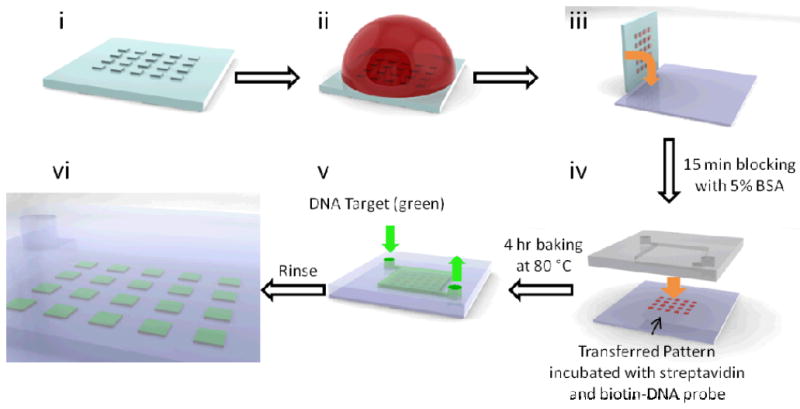
Process flow for surface patterning of biomolecules and bonding. The stamp is first inked with 1 mg/mL BSA-biotin solution (ii), dried with nitrogen and stamped onto a pristine glass slide with finger pressure (iii). The pattern is then incubated with a 5% (wt/v) BSA solution in phosphate-buffered saline (PBS) for 15 minutes for blocking, followed by a droplet of 1 mg/mL streptavidin and then 100 nM biotin-modified Kras-capturing DNA for 1 hour and overnight, respectively. The patterned substrate is then bonded to a PDMS chamber that has either been activated by oxygen plasma, or polymer-grafted and hydrolyzed. After a 4-hour baking step, the Cy5-labeled DNA target oligonucleotides are introduced and DNA capture is observed under fluorescence scanner
A 1 uM Cy-5 labelled target DNA is introduced onto the finished devices and left to incubate for 2 hours, followed by washing with Millipore water for 30 minutes using a syringe pump. The devices are then mounted using glycerine and scanned using a Typhoon 9410 scanner (GE Healthcare Bio-Sciences Corp.) (800 V, 10 micron resolution).
3. Results
3.1 Verification of Modification
Because the grafted polymer is very thin, and MAP-TMS is compositionally very similar to PDMS, characterization of the modification can only be performed using ATR-FTIR. Specifically, the monomers contain a carbonyl carbon, which is absent in PDMS, and ATR-FTIR is used to detect C=O stretch at around 1720cm-1 (Figure 1). In addition, when left in a humid environment for several weeks, the appearance of the modified PDMS turned from clear to cloudy. Microscopic inspection of the surface reveals the formation of small, clear bumps on the surface which gives a frosted appearance (Supplementary Figure 2). Furthermore, after soaking in buffered hydrofluoric acid (BHF) for 30 minutes, clarity of the PDMS was restored (Supplementary Figure 3); this suggests the glass-like nature (i.e. containing Si-O-Si bonds) of the microscopic bumps arising from the condensation of the high-density silanols, and serves as a proxy indication of successful polymer grafting. There is little risk of occlusion of the channels by these bumps in most applications, which are less than 100nm tall as measured using a surface profilometer (Daktek IIA). In addition, channels as shallow as 500 nm have remained patent after polymer grafting and bonding to a glass slide (Supplementary Figure 4).
Fig. 1.

ATR-FTIR of the polymer-grafted surface. It is known that PDMS does not have significant absorbance at around 1720 cm-1. The appearance of this absorbance peak can be attributed to the C=O bond stretching on the carbonyl group present in all the monomers.
3.2 Bonding Strength
The derivatized PDMS surface does not bond until activation of the grafted polymer by hydrolysis of the Si-O-methyl alkoxysilane bond, which yields methanol and a Si-OH silanol group. The latter is also the reactive group that is generated on both glass and PDMS surfaces during oxygen plasma treatment, which undergo condensation reactions to form Si-O-Si covalent bonds.8, 28 Since the polymeric form of MAP-TMS will generate high-density silanols upon hydrolysis which are prone to self-condensation,29 it is necessary to minimize condensation within polymer chains by performing an acidic hydrolysis in a 30mM pH 4 acetate buffer. Rinsing with neutral pH water after activation removes the residual acidic buffer and allows the condensation reaction to occur when the polymer-grafted surface is placed on the glass substrate. Depending on the type of copolymer used in addition to MAP-TMS, the time to reach full bonding strength (defined as 80 psi pressure without signs of failure) is anywhere from 4 to 16 hours (Figure 2C). Once bonded, the PDMS cannot be peeled from the glass without tearing, suggesting that the bonding strength is at least as strong as the PDMS material bulk strength (Figure 2B).
To ensure that the bonding is not due to radicals generated on the PDMS surface by exposure to UV, UV-exposed PDMS with no grafting and polymer-grafted PDMS stored in a desiccator for 40 days were brought into contact with pristine glass slides after activation in acetate buffer. While the latter yielded similar bonding strengths to freshly-prepared polymer-grafted PDMS, the former was not bonded at all, indicating that the grafted polymer is necessary for bonding. Furthermore, while it is known that PDMS exposed to oxygen plasma also possess silanols, bonding of a treated PDMS to an untreated soda lime glass surface failed at around 5 psi. We hypothesize that in addition to the large number of reactive groups, the flexible polymeric chains are also able to extend into the nano-crevices on the surface of the glass, reacting with silanols on the glass surface that are not accessible to plasma-generated silanols, hence contributing to greater bonding strength (Scheme 1B, Supplementary Figure 5). The devices also remain bonded at full strength one year after bonding, and left in the open without any special storage condition, attesting to the stability of the bond.
3.3 Effects of Grafting Methods
Grafting reactions are carried out by both ‘grafting-to’ and ‘grafting-from’ reactions (Scheme 1A). ‘Grafting-to’ reactions are performed by growing a polymer chain in solution using photoinitiated free-radical polymerization, which is then grafted onto the surface of the device during the termination step, in which the propagating chain reacts with the C=C bond introduced as described in Section 2.2. This has the advantage of being faster, since photoinitiators can be used, and theoretically the initiator/monomer ratio can be used to exert some level of control over the chain length. In our case, characterization of the chain length by chromatography is hampered by the insolubility of the polymer in most common mobile phases. Furthermore, as reported in literature, grafting-to reactions tend to have limited graft density due to steric hindrance,30 as evidenced by the slower bond formation (Table 1) and also lower density of microscopic bumps after exposure to humidity (Supplementary Figure 2).
Table 1.
Bonding time and strength for grafted MAP-TMS/Acrylamide 2:1 molar ratio using either grafting-to or grafting-from polymerization
| Bonding Time | |||
|---|---|---|---|
|
| |||
| Method | UV Dose | 4 hours | 16 hours |
| Grafting-To | 0.144 kJ/cm2 @365 nm | 23 psi | > 80 psi |
| Grafting-From | 0.325 kJ/cm2 @253 nm | > 80 psi | > 80 psi |
‘Grafting-from’ polymerization relies on the generation of radicals on the surface of the PDMS. Since there is no easy way to covalently attach photoinitiators onto the surface of the PDMS, we perform scission of the Si-CH3 bond using a 253 nm germicidal UV lamp. Because the polymerization depends on a relatively small number of radicals, and polymer chains only propagate when a monomer is close enough to the radicals, a fairly long reaction time is required, with a typical reaction taking place overnight. Despite the longer reaction time, the ‘grafting-from’ approach yields a much better bond and denser grafting (Supplementary Figure 2),31 able to yield a full-strength interface in 4 hours (Table 1), and is thus considered somewhat preferable.
3.4 Composition of Polymer and Rate of Bond Formation
The co-polymers are used to confer different hydrophobicities to the polymers, and also to provide spacers to mediate silanol density (Scheme 1A). We found that using a hydrophobic copolymer like methyl methacrylate resulted in a much slower bond formation, while hydrophilic co-polymers like acrylamide and acrylic acid allowed bond formation to occur faster (Figure 2C). This can be attributed to the rate of hydrolysis, which will presumably be increased with more hydrophilic polymers that allows water to access the alkoxysilanes on the polymer chains. This in turn increases the silanol surface density, which will understandably increase the condensation reaction rate.
In addition, without any spacers, the bonding strength was quickly achieved since the molar concentration of MAP-TMS is high (total molar concentration of monomers is conserved in all experiments). However, localized failure of MAP-TMS-only devices occurred frequently, which we attribute to the self-condensation reaction occurring within or between adjacent polymer chains, forming cyclic species and reducing the number of available silanols in isolated regions.32 It is important to note that the results here do not necessarily account for different polymer chain lengths, which is difficult to determine. Nonetheless, under the reaction conditions stated, it appears that a 2:1 MAP-TMS/acrylamide ratio yields the best results, and unless otherwise stated, bonding to glass with 4-hour baking is used in all experiments.
3.5 Effects of Substrate-Copolymer Combination
Different types of glass can be used for fabricating microfluidic devices. While not frequently discussed, soda lime glass slides typically yield poorer bonds with PDMS than low-iron water white glass such as Fisherfinest coverslips when bonded using oxygen plasma treatment. This can be attributed to the different composition as well as the different surface smoothness of the different glass slides, with the coverslips having a much smoother finish. We have found that while it is possible to attain very strong bonds with both types of glass, there is a dependence on the copolymer used.
Of the copolymers we have tested, we found that acrylamide bonded more strongly with soda lime glass than acrylate, and vice versa for water white glass (Table 2). While the source of this specificity is unclear, it points to the possibility of tailoring the properties of the grafted polymer for different substrates.
Table 2.
Effects of substrate-copolymer combination and grafting method on burst pressure after 16-hours baking
| Copolymer | Substrate | Burst Pressure | GF/GTa |
|---|---|---|---|
| AAm | Soda-Lime | > 80 | GT |
| AAm | Water-White | 12 | GT |
| AAc | Soda-Lime | 40 | GT |
| AAc | Water-White | > 80 | GT |
| AAm | Soda-Lime | > 80 | GF |
| AAm | Water-White | 33 | GF |
| AAc | Soda-Lime | > 80 | GF |
| AAc | Water-White | > 80 | GF |
GF and GT refer to ‘grafting-from’ and ‘grafting-to’ methods, respectively
3.6 Compatibility with biomolecule-functionalized surfaces
An application of the bonding technique described in our work is that of a patterned DNA sensor array, which can be coupled to other microfluidic elements for upstream sample preparation.33 We fabricated a DNA sensor that has a single type of DNA capture probe specific for a KRAS sequence, though this can be easily extended to multiple probes using existing DNA spotting technologies. A BSA-anchored biotin-steptavidin-biotin sandwich layer is used to introduce DNA capture probe in a grid pattern onto a plain glass slide (Figure 3A). Bonding of the molded PDMS chamber over the pattern is achieved either using our method or oxygen plasma treatment to activate the surfaces. We noted that upon exposure to plasma, many of the patterned glass slides exhibited a greasy appearance, which made the bond extremely weak, whereas our polymer-modified PDMS bonded without issue. The target capturing experiment was conducted using low flow rates to drive the solution into the chamber. Comparing the results in Figure 3B, we can clearly see that exposure to oxygen plasma has destroyed practically all the capture probes on the surface of the glass, resulting in nearly no target capture at all. In contrast, the grid pattern is clearly visible in the device bonded using the polymeric MAP-TMS. It is noted that as reported in other grafting procedures, cloudiness of the PDMS surface sometimes occurs in devices with extensive polymer grafting.34 Self-condensation of some MAP-TMS polymer chains also contributes to the change in clarity of the devices. However, for most applications, the assays can be observed using bottom-side scanning instead, since it is not desirable to make measurements through the PDMS in any case.
Fig. 3.

A.) BSA-anchored biotin-streptavidin-biotin sandwich layer is used to immobilize a DNA capture probe on a glass coverslip. The patterned glass is sealed in a chamber using either oxygen plasma or our polymer-graft and baked for 4 hours. The Cy5-modified target oligo-DNA is introduced and after hybridization for 2 hours and rinsing for 30 minutes, the device is imaged using Typhoon scanner. B.) While the device sealed with oxygen plasma was almost devoid of any patterns (top), the device bonded using our bonding technique clearly shows the patterned capture probe (bottom), thereby demonstrating our method’s compatibility with biological molecules (fluorescent squares are 200-by-200 microns).
4. Discussion
A major bottleneck in the adoption of existing microfluidic technologies is that traditional process flows are often incompatible with the biological molecules that one may be interested in introducing to the surface of the devices.35, 36 Open-chamber devices including DNA, RNA and protein microarrays,37 as well as some electrowetting on a dielectric (EWOD) devices38 do not require any bonding and can be easily patterned with different biomolecules, and are therefore being used in an increasingly wide range of applications. However, they are also unsuitable for other purposes, such as when nano- or picoliter-scale solution volumes are desired.39 Furthermore, integration of open-surface systems with closed-chamber microfluidic devices for sample preparation remains challenging.33 While patterning of pre-sealed glass-PDMS devices is possible using various schemes, 40, 41 they typically lack the flexibility, throughput and simplicity of microcontact printing techniques such as those used in microarray fabrication due to the limitations to physical access. On the other hand, liquid-based adhesives can cause clogging in fluidic channels,13 some of which may be shallower than one micron in height
iCVD-based bonding methods solve many of the limitations of conventional bonding approaches. By introducing thin, conformal polymer layers onto the surface of the substrates, clogging of the channels do not occur.14 Since the deposition and polymerization is not substrate-specific, the method has also been shown to be applicable to a range of materials, including glass, silicon, plastics, and PDMS.15, 18 However, because the material is uniformly deposited on both surfaces, its applications exclude any substrate with pre-patterned molecules such as proteins. While post-deposition patterning can be performed, the fact that the whole substrate is covered by a polymer means that the molecule of interest must be derivatized with a complementary functional group before conjugation can take place.18, 20
Our bonding technique addresses many of these concerns. Each monomer of MAP-TMS contains a methacrylate as well as a trimethoxysilane group. By polymerizing the methacrylate portion of these monomers, we are able to obtain a very large number of methoxysilane groups on the polymer chains, each of which can react with a silanol group on the glass surface to create a covalent bond through a condensation reaction. This high density of covalent bonds allows the formation of a very strong PDMS-glass interface. Since our grafted polymer is extremely thin, there is no risk of channel clogging, as evidenced by the device patency test (Supplementary Figure 4). In addition, the method does not require any modification of the glass substrates, therefore we are free to introduce thiol, amine, epoxide and other functional groups to the surface using microcontact printing of organosilanes.27 Besides acting as coupling agents for different conjugation chemistries, these functional groups may also be interesting subjects for investigation, such as the behaviour of cells when exposed to different surface chemistries.42 Biomolecules can also be introduced to the glass substrate using modified BSA, as demonstrated in this work.
By allowing a variety of organic and biomolecules to be patterned prior to sealing inside a microfluidic device, we have the ability to introduce multiplexed probes using existing microcontact printing techniques, coupled to an on-chip sample manipulation and preparation system, and hence to approach more closely an actual “lab-on-a-chip” solution. Furthermore, by pre-fabricating generic PDMS designs and modifying them with our polymer, end-users can potentially tailor the glass surface with different probes according to their own needs, detecting proteins, DNA and RNA, thereby introducing a level of customizability to the devices. Finally, although reversible packaging techniques exist, they are either unsuitable for high pressure applications, or may involve cumbersome clamping setups, which limit their applications.35,35, 36 Bonding using the grafted polymer proposed here is no different than normal oxygen plasma bonding in terms of form factor and bonding strength.
As an added bonus, while PDMS bonding to glass is an application of great utility, the bonding technique is also applicable to other types of surfaces. Other than the conditions described, bonding to plain polystyrene and silicon wafer (via the native oxide layer) has been achieved. Room temperature-bonding to glass, silicon and polystyrene have also been accomplished, and this will potentially allow us to seal confluent cell layers into microfluidic devices. In order to further extend the accessibility of this technique, we have also successfully grafted the polymer using the ‘grafting-from’ approach without any MAP-TMS modification of PDMS, instead relying solely on the UV irradiation to perform the grafting. This will allow any laboratory with access to a germicidal UV lamp to perform the grafting, and hence work with microfluidic devices. These alternative processes are currently being optimized for optimal strength and processing time.
As demonstrated in this work, through the judicious use of different copolymers, reactivity to different substrates, attainable strength and rate of bond formation can be tuned for specific applications. Although the conditions for these alternative processes have not been optimized, they nonetheless point to the potential of our technique in a broad range of applications.
5. Conclusions
In this work, we have created a brand new method of bonding that is not only strong, but has a long shelf-life. Activation is extremely convenient, requiring nothing more than simple acidic buffer. Furthermore, it allows an alternative process flow that is compatible with biological molecules, the difficulty in the incorporation of which has long been an Achilles’ heel of microfluidics. Finally, like any polymer, the properties of the grafted moiety are highly tuneable. As such, we believe that potent as this new technique is, it is only scratching the surface of what is possible in polymer-grafted bonding techniques. Depending on the different substrates, different sorts of monomers can be used to confer bonding capabilities, thereby extending the reach of microfluidics in research as a whole.
Supplementary Material
Acknowledgments
The authors would like to thank DARPA (Micro/Nano Fluidics Fundamentals Focus Centre), NIH (R01CA155305, U54CA151838) and A*STAR Graduate Scholarship.
Footnotes
Electronic Supplementary Information (ESI) available: Supplementary Figures 1-5. See DOI: 10.1039/b000000x/
Contributor Information
Cyrus Weijie Beh, Email: wbeh1@jhmi.edu.
Tza-Huei Wang, Email: thwang@jhu.edu.
Notes and references
- 1.Yager P, Edwards T, Fu E, Helton K, Nelson K, Tam MR, Weigl BH. Nature. 2006;442:412–418. doi: 10.1038/nature05064. [DOI] [PubMed] [Google Scholar]
- 2.Squires T. Reviews of Modern Physics. 2005;291:1059–1026. [Google Scholar]
- 3.Tran TH, Nguyen CT, Kim D-P, Lee Y-k, Huh KM. Lab on a Chip. 2012;12:589–594. doi: 10.1039/c1lc20769e. [DOI] [PubMed] [Google Scholar]
- 4.Chin CD, Laksanasopin T, Cheung YK, Steinmiller D, Linder V, Parsa H, Wang J, Moore H, Rouse R, Umviligihozo G, Karita E, Mwambarangwe L, Braunstein SL, van de Wijgert J, Sahabo R, Justman JE, El-Sadr W, Sia SK. Nat Med. 2011;17:1015–1019. doi: 10.1038/nm.2408. [DOI] [PubMed] [Google Scholar]
- 5.Mao X, Huang TJ. Lab on a Chip. 2012 [Google Scholar]
- 6.Klapperich CM. Expert review of medical devices. 2009;6:211–213. doi: 10.1586/erd.09.11. [DOI] [PubMed] [Google Scholar]
- 7.Hu G, Gao Y, Sherman P, Li D. Microfluidics and nanofluidics. 2005;1:346–355. [Google Scholar]
- 8.Bhattacharya S. Journal of Microelectromechanical Systems. 2005;8:1063–1597. [Google Scholar]
- 9.Franssila S. Introduction to Microfabrication. John Wiley & Sons; 2010. [Google Scholar]
- 10.Nelson KE, Foley JO, Yager P. Analytical Chemistry. 2007;79:3542–3548. doi: 10.1021/ac062349w. [DOI] [PMC free article] [PubMed] [Google Scholar]
- 11.Puleo CM, McIntosh Ambrose W, Takezawa T, Elisseeff J, Wang T-H. Lab on a Chip. 2009;9:3221–3227. doi: 10.1039/b908332d. [DOI] [PubMed] [Google Scholar]
- 12.Yang C, Wang W, Li Z. 2009 4th IEEE International Conference on Nano/Micro Engineered and Molecular Systems; 2009. pp. 319–322. [Google Scholar]
- 13.Becker H, Gärtner C. Electrophoresis. 2000;21:12–26. doi: 10.1002/(SICI)1522-2683(20000101)21:1<12::AID-ELPS12>3.0.CO;2-7. [DOI] [PubMed] [Google Scholar]
- 14.Im SG, Bong KW, Lee C-H, Doyle PS, Gleason KK. Lab on a chip. 2009;9:411–416. doi: 10.1039/b812121d. [DOI] [PubMed] [Google Scholar]
- 15.Xu J, Gleason KK. Chemistry of Materials. 2010;22:1732–1738. [Google Scholar]
- 16.Lee NY, Chung BH. Langmuir : the ACS journal of surfaces and colloids. 2009;25:3861–3866. doi: 10.1021/la802823e. [DOI] [PubMed] [Google Scholar]
- 17.Aran K, Sasso La, Kamdar N, Zahn JD. Lab on a chip. 2010;10:548–552. doi: 10.1039/b924816a. [DOI] [PMC free article] [PubMed] [Google Scholar]
- 18.Chen H-Y, McClelland Aa, Chen Z, Lahann J. Analytical chemistry. 2008;80:4119–4124. doi: 10.1021/ac800341m. [DOI] [PubMed] [Google Scholar]
- 19.Lau KKS, Gleason KK. Macromolecules. 2006;39:3688–3694. [Google Scholar]
- 20.Chen H-Y, Lahann J. Analytical Chemistry. 2005;77:6909–6914. doi: 10.1021/ac050964e. [DOI] [PubMed] [Google Scholar]
- 21.Végvári Á, Hjertén S. Journal of Chromatography A. 2002;960:221–227. doi: 10.1016/s0021-9673(01)01436-4. [DOI] [PubMed] [Google Scholar]
- 22.Hwang S-y, Jin L-t, Yoo G-s, Choi J-K. Electrophoresis. 2006;27:1744–1748. doi: 10.1002/elps.200500601. [DOI] [PubMed] [Google Scholar]
- 23.Hu S, Ren X, Bachman M, Sims CE, Li GP, Allbritton N. Analytical chemistry. 2002;74:4117–4123. doi: 10.1021/ac025700w. [DOI] [PubMed] [Google Scholar]
- 24.Hu S, Ren X, Bachman M, Sims CE, Li GP, Allbritton N. Electrophoresis. 2003;24:3679–3688. doi: 10.1002/elps.200305592. [DOI] [PubMed] [Google Scholar]
- 25.Zhuravlev LT. Langmuir. 1987;3:316–318. [Google Scholar]
- 26.Tomozawa M. Journal of the American Ceramic Society. 1985;68:C-251–C-252. [Google Scholar]
- 27.Heise C, Bier F, Wittmann C. Vol. 261. Springer; Berlin / Heidelberg: 2005. pp. 1–25. [Google Scholar]
- 28.Malecha K, Gancarz I, Golonka LJ. Journal of Micromechanics and Microengineering. 2009;19:105016. [Google Scholar]
- 29.Brochier Salon M-C, Bayle P-A, Abdelmouleh M, Boufi S, Belgacem MN. Colloids and Surfaces A: Physicochemical and Engineering Aspects. 2008;312:83–91. [Google Scholar]
- 30.Sumerlin BS, Neugebauer D, Matyjaszewski K. Macromolecules. 2005;38:702–708. [Google Scholar]
- 31.Matyjaszewski K, Tsarevsky NV. Nat Chem. 2009;1:276–288. doi: 10.1038/nchem.257. [DOI] [PubMed] [Google Scholar]
- 32.Torry SA, Campbell A, Ã AVC, Tod DA. Journal Of Adhesion. 2006;26:40–49. [Google Scholar]
- 33.Kim J, Johnson M, Hill P, Gale BK. Integrative Biology. 2009;1:574–586. doi: 10.1039/b905844c. [DOI] [PubMed] [Google Scholar]
- 34.Hu S. Macromolecules. 2005;38:6592–6597. [Google Scholar]
- 35.Park JJ, Luo X, Yi H, Valentine TM, Payne GF, Bentley WE, Ghodssi R, Rubloff GW. Lab on a Chip. 2006;6:1315–1321. doi: 10.1039/b603101c. [DOI] [PubMed] [Google Scholar]
- 36.Koev ST, Dykstra PH, Luo X, Rubloff GW, Bentley WE, Payne GF, Ghodssi R. Lab on a Chip. 2010;10:3026–3042. doi: 10.1039/c0lc00047g. [DOI] [PubMed] [Google Scholar]
- 37.Seidel M, Niessner R. Analytical and bioanalytical chemistry. 2008;391:1521–1544. doi: 10.1007/s00216-008-2039-3. [DOI] [PMC free article] [PubMed] [Google Scholar]
- 38.Malic L, Veres T, Tabrizian M. Lab on a Chip. 2009;9:473–475. doi: 10.1039/b814697g. [DOI] [PubMed] [Google Scholar]
- 39.Teh S-Y, Lin R, Hung L-H, Lee AP. Lab on a chip. 2008;8:198–220. doi: 10.1039/b715524g. [DOI] [PubMed] [Google Scholar]
- 40.Liu J, Gao D, Li H-F, Lin J-M. Lab on a Chip. 2009;9:1301–1305. doi: 10.1039/b819219g. [DOI] [PubMed] [Google Scholar]
- 41.Frampton J, Lai D, Sriram H, Takayama S. Biomedical Microdevices. :1–9. doi: 10.1007/s10544-011-9574-y. [DOI] [PubMed] [Google Scholar]
- 42.Curran JM, Chen R, Hunt JA. Biomaterials. 2005;26:7057–7067. doi: 10.1016/j.biomaterials.2005.05.008. [DOI] [PubMed] [Google Scholar]
Associated Data
This section collects any data citations, data availability statements, or supplementary materials included in this article.