Abstract
Electronic states at domain walls in bilayer graphene are studied by analyzing their four- and two-band continuum models, by performing numerical calculations on the lattice, and by using quantum geometric arguments. The continuum theories explain the distinct electronic properties of boundary modes localized near domain walls formed by interlayer electric field reversal, by interlayer stacking reversal, and by simultaneous reversal of both quantities. Boundary mode properties are related to topological transitions and gap closures, which occur in the bulk Hamiltonian parameter space. The important role played by intervalley coupling effects not directly captured by the continuum model is addressed using lattice calculations for specific domain wall structures.
Keywords: topological states, topological defects, layer-stacking walls, few-layer graphene
The electronic properties of few layer graphene systems depend sensitively on the atomic registry between neighboring layers (1) with important consequences for applications in graphene-based electronics. Unlike single-layer graphene, bilayer graphene (BLG) with  stacking is converted from a semimetal to a small gap semiconductor by the application of a perpendicular electric field (2–6). This occurs because (i) the interlayer hybridization of orbitals on eclipsed lattice sites breaks the sublattice symmetry on each layer, replacing the pseudorelativistic description of single layer graphene by a theory in which two quadratically dispersing chiral bands touch at discrete points in momentum space (2, 7), and (ii) the perpendicular electric field further breaks inversion symmetry, creating a semiconductor by gapping these low-energy degrees of freedom. The possibility of exploiting this type of field tunable gap is being vigorously pursued in ultraclean dual-gated devices (8–11).
It has been appreciated that this field-induced gap admits a topological interpretation (12, 13). The low-energy theory for BLG can be represented by an effective two-band model from which it is readily seen that inversion-symmetry breaking induces large momentum-space Berry curvatures (13, 14). The Berry curvatures have opposite signs near the two inequivalent Brillouin-zone corners (valleys) at which gaps are opened, so the integral of the Berry curvature over the full Brillouin zone is zero. Nonetheless, the integral of the Berry curvature within a single valley is nonzero, and this allows a topological analysis of the valley-projected electronic spectrum. This idea has been developed in a continuum analysis of the subgap electronic states bound to a BLG domain wall formed by a sign reversal of the interlayer electric field (12, 15–19). These electric-field walls (EFWs) are predicted to bind pairs of subgap chiral copropagating boundary modes, an interesting feature that can be related to the change in sign across a domain wall of a valley-projected topological index.
In this article, we examine the related BLG domain wall problem in which the interlayer electric field is uniform but the layer stacking switches from  to
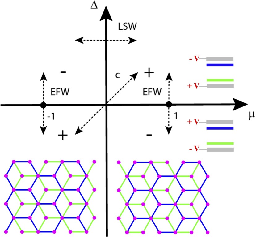
to  registry. This version of the problem changes the boundary conditions for matching the electronic states of the two bounding phases and requires that we augment the two-band model of BLG (2, 12, 13) by accounting for all four of its sublattice degrees of freedom. Nonetheless, we find that layer-stacking walls (LSWs) bind electronic states with the same chiral structure as for the EFW studied previously. Here, we make this connection explicit by mapping the two problems onto each other within a family of four-band BLG Hamiltonians. Our results demonstrate that the topological transition in a LSW structure is associated with a finite momentum gap closure in the parameter space of four-band BLG Hamiltonians. We construct a phase diagram (Fig. 1) that identifies the different types of topologically protected states that are possible in BLG samples in which both the interlayer electric field and the layer stacking order vary in space. This analysis identifies yet a third type of domain wall in which the two pairs of chiral modes within a single valley are coupled, gapping the spectrum and annihilating boundary modes. Our results are supported by a continuum analysis of the domain wall states, lattice calculations for specific defect structures, and analysis using quantum geometrical arguments. Taken together, these elements provide a general framework for understanding the origin of the valley-projected topological states in BLG, and their fate in the presence of intervalley scattering.
Fig. 1.
A phase diagram illustrating the distinct valley-projected topological phases of BLG and the critical lines that separate them. A sign change of  denotes a reversal of the interlayer electric field. A sign change of μ denotes a transition from
  to
to  interlayer registry. The spectrum is gapped except along the lines
  and
and  .
.
Two-Band Continuum Formulation
The electronic states for BLG can be represented by four-component wave functions  , where ψ denotes the atomic orbital centered on the A or B sites of the top or bottom layer. At low energies, the Hamiltonian can be expanded for small
  around the two inequivalent Brillouin zone corners:
  with
with  denoting K and
  . Using Pauli matrices
  to represent operators that act on the sublattice degree of freedom within a layer and
  to represent operators acting on the layer degree of freedom, the BLG Hamiltonian can separated into layer diagonal and layer off-diagonal contributions by writing
  . We find that for
  stacked BLG in which the A sites of top layer hybridize with the B sites of the bottom layer,
  and
and  with
with  , where energies are normalized by
  ,
,  is the nearest-interlayer-neighbor hopping amplitude, and v is the electron velocity in an isolated layer. For the reversed
  stacking order, the interlayer coupling term becomes
  . When present, an electric potential difference V adds
  with
with  to the Hamiltonian.
When  , it is convenient to eliminate the high energy degrees of freedom at
  to arrive at an effective low-energy two-band model (2) as follows:
where the  matrices act on two component spinors
  in the low-energy subspace for
  BLG and
  . Eq. 1 admits a geometrical interpretation in which the negative energy eigenstates are spinors aligned with
  , and the filled band has a momentum space Berry curvature (13, 14) as follows:
 |
Because of the ν dependence in Eq. 2 the integral of  over the full Brillouin zone is zero and the filled valence band carries total Chern number
  as required by time reversal symmetry. However, for small
  , the Berry curvature is strongly peaked at the gap minima near K and
  . Consequently, the integral of
  over an individual valley is accurately defined and the “valley Chern number”
  . The valley Chern number changes by
  across an EFW, which can be associated with the appearance of pairs of valley-projected edge modes copropagating along the boundary. These chiral modes have been obtained by analytic solution of the low-energy two-band model in the presence of a sharp EFW and by numerical solution for a spatially varying
  that smoothly connects two electric-field reversed states (12). As noted in previous work (13, 15), the introduction of a valley Chern number in this context is approximate because strictly speaking the construction does not map the full periodic Brillouin zone onto the parameter space of
  . Nonetheless, when
  is small and intervalley scattering is absent the computed change
  can be interpreted as a topological quantity, because
  is integrated over a closed surface produced by “gluing together” two integrals for the individual
  along a common boundary.
Layer Stacking Walls
We now turn to the case of a LSW at which the bilayer registry reverses from local  to local
  with
with  held constant. Crossing a LSW changes the interlayer coupling matrix
  and switches the orbitals that span its low-energy subspace. In this case, evaluation of the Berry curvature requires consideration of all four degrees of freedom in the bilayer Dirac problem. Alternatively, one can identity the topological origin of LSW modes by examining the residual phase twists induced at large momentum q in the eigenstates of the generalized Hamiltonian,
which reduces to the  forms when
  . For
. For  degenerate single layer states
  deep in the filled band with energies
  are split by
  and are mixed by γ in the projected Hamiltonian,
where  are
are  Pauli matrices acting in the
  subspace and
  . For large q, the eigenstates
  written in the original four orbital basis are as follows:
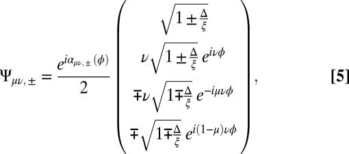 |
where  , and we explicitly display the overall
  phases
  . Using Eq. 5, we calculate the momentum space Berry connection as follows:
 |
The change in the valley Chern numbers upon passing from the  to
to  states is obtained from the loop integral of the trace of
  over μ and band indices
  , which reads as follows:
Here,  are integer valued winding numbers of the overall phases
  . The
. The  dependence of this result vanishes after tracing over the filled bands, demonstrating that the valley Chern number in BLG is shared among all of the occupied bands rather than being confined just to its low-energy states as is often assumed.
  is a topological index provided that the difference is evaluated in the same gauge for the two bounding phases, which requires that
  for this boundary. It follows that
  and therefore that a domain wall separating insulating regions with local
  and
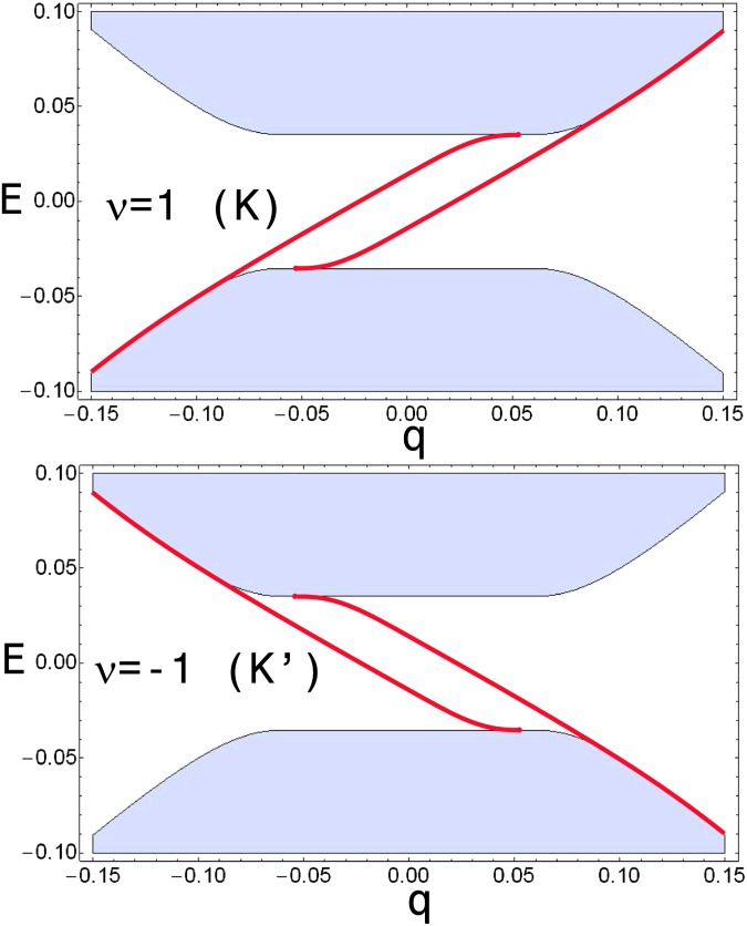
and  registry will also confine pairs of valley-projected chiral modes propagating along the boundary with opposite velocities in the two valleys. Fig. 2 confirms this result by showing the spectra calculated by matching the full four-component wave functions of Eq. 3 across a sharp boundary where μ switches from 1 to
  .
.
Fig. 2.
Propagating chiral boundary modes (red) near the K (Upper) and  (Lower) points calculated using the four-band continuum model for a domain wall separating regions with local
  and
and  stacking registry in the presence of a uniform layer-potential difference
  . The shaded regions show the support of the continuous bulk spectrum as a function of momentum
  parallel to the domain wall. The results were obtained for the parameter values
  .
.
Using Eq. 5, we find that at large q the wave functions on the two sides of the LSW are related by a gauge transformation,
with a different phase twist induced in each layer. It follows from the accumulation of internal phases in the two layers that  . EFW walls, where the sign of the potential difference between layers
  switches but the atomic registry μ does not change, can be analyzed similarly. Although
  does not appear explicitly in
  in Eq. 7, there is an implicit dependence through the
  phase prefactors. We find the following:
i.e., that a sign reversal in  can be absorbed in a sign change of μ combined with a change of basis. Using this construction, the negative-energy eigenstates at large
  on the two sides of the EFW are related by the following
  gauge transformation:
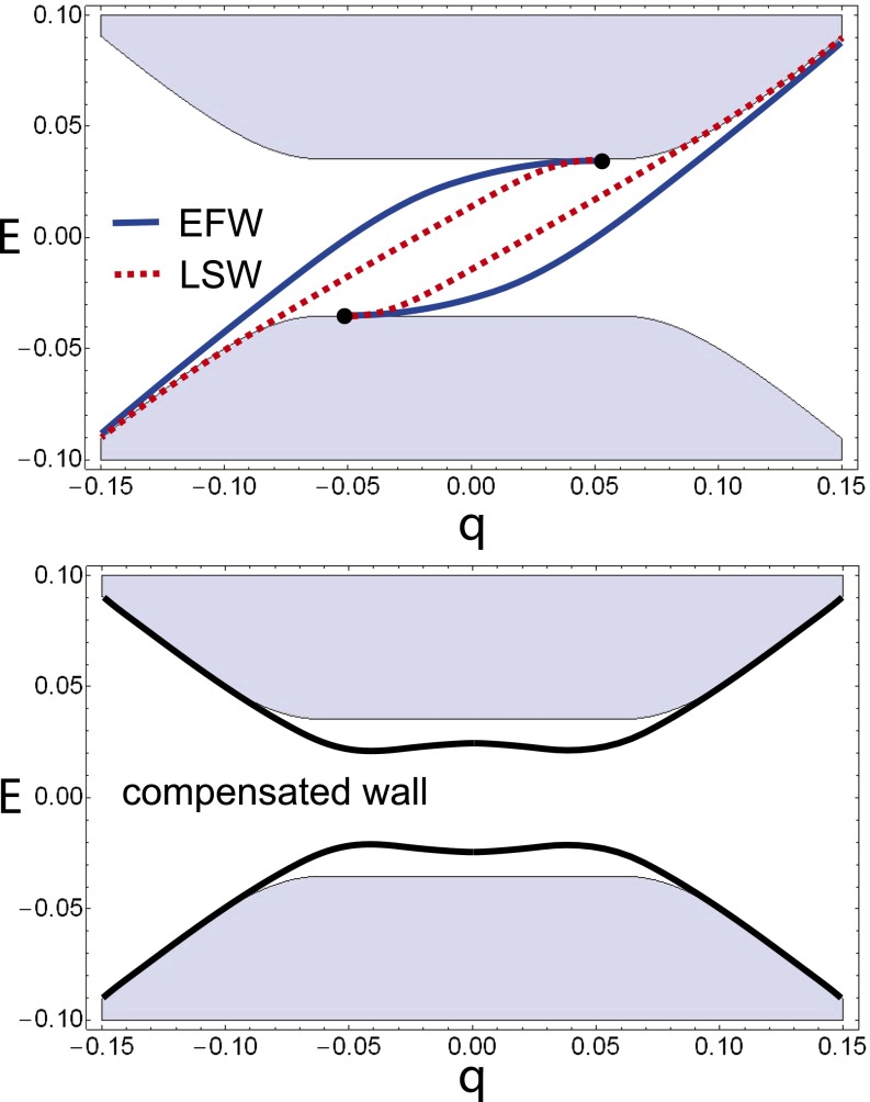
which produces the same overall  for the EFW. Eqs. 8–10 compactly express the relationship between these two different types of domain wall in the four-band theory. This is also illustrated in Fig. 3, which compares the valley K spectra computed for an EFW and a LSW showing their common chiral boundary modes.
Fig. 3.
(Upper) Comparison of valley K domain wall spectra for electric-field and layer-stacking walls. Both walls support a pair of copropagating chiral modes. (Lower) Interface spectrum calculated with a four-band theory for a topologically compensated boundary at which both layer stacking and electric field change sign. In this case, the boundary spectrum is completely gapped even in a continuum model.
In the LSW case, unlike the EFW case, analyzing the continuity of wave functions across the interface requires consideration of all four bands. The common topological origin of the domain wall spectra therefore becomes apparent only in a four-band continuum theory. Nevertheless, by integrating out the high-energy bands at energies of  , we are able to construct a two-band effective model away from the domain wall in which for either case
  is assigned to a sign change of the Berry curvature of the lower band. In this approach, Eq. 1 reads
  with
with  layer Pauli matrices that act on different spinors in the
  cases: on
  for
for  and on
  for
for  . Because of inversion symmetry breaking, the valence band acquires a momentum space Berry curvature (13, 14),
 |
which integrates over a single valley to  . Obviously, the valley Chern number changes by two across either an EFW or a LSW. Based on the bulk-boundary correspondence, pairs of valley-projected edge modes should copropagate along the interface.
Phase Diagram
The  plane phase diagram in Fig. 1 identifies distinct BLG topological phases. Phase boundaries occur along the μ and
  axes where the spectrum of
  undergoes gap closures at
  .
.  describes an ungapped BLG system in which quadratic band crossing occurs exactly at
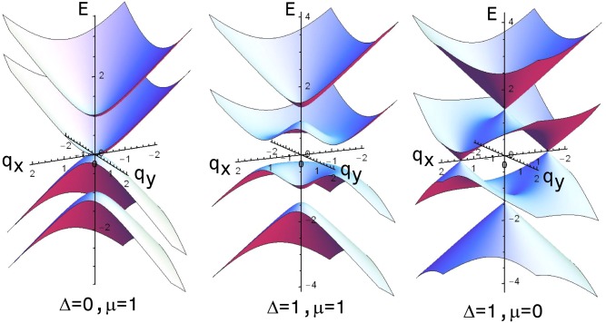
  , as seen in Fig. 4, Left. The gaps that open for the case of
  and
and  are the electric field induced gaps easily understood within a two-band model. The boundary with
  and
and  also has a gap closure, but it occurs at two finite momenta
  along the
  line where band crossing is possible because
  is a constant of the motion. For deviations in either
  or
or  , the degeneracies at the band-crossing points are lifted at linear order, implying the conical gap closure illustrated in Fig. 4, Right. When
  , the original quadratic gap closure fissions into a pair of linear Dirac singularities each of which carries one-half of the original winding number. Trajectories in the Hamiltonian parameter space that connect these topologically distinct ground states and involve different parameter values can shift the momenta at which the gap closures occur, but cannot eliminate them. For example, when
  but
but  in Eq. 3 the layers decouple and the gap closure at
  degenerates to a closed Fermi ring with radius
  .
.
Fig. 4.
Bulk band structures of three forms of BLG. (Left) BLG with uniform AB registry and no interlayer electric field characterized by quadratic touching between its two low energy bands. (Center) The field-induced gapped phase in which the BLG degeneracy is lifted by an interlayer electric field. (Right) A critical state with nonzero interlayer electric field where gap closure occurs at  as BLG crosses from
  to
to  registry. The zero energy gap closures in the left and right panels separate four distinct gapped phases of BLG as shown in Fig. 1.
Fig. 1 also illustrates the possibility of a third type of compensated domain structure (labeled c) at which both the layer registry and interlayer electric field are reversed. Variation of local band parameters along this line connects two bilayer states that are distinct but have  . As illustrated in Fig. 3, Lower, spectra obtained by matching solutions across this compensated domain wall demonstrate that it hosts two pairs counter propagating modes within the same valley, which hybridize and completely gap the spectrum.
Fragility of Boundary Modes
The continuum model is able to explain the topological origin of the gapless interface modes. However, the short-range physics near the domain wall, which may be of essential significance, is not captured in the continuum Hamiltonian. Importantly, the single-valley physics that protects the chiral domain wall solutions can be preempted by sufficiently strong large-momentum scattering that acts to recouple states in the two valleys. In fact, Fig. 2 suggests that these single-valley domain wall modes ultimately reconnect with each other. What is critical is whether valley is a good quantum number. If it is not in the bulk, then there is no well defined topological invariant even at low-energy. If it is broken on the boundary, then there are no well controlled physical consequences even if one can define the bulk invariant. To study this further, we construct a specific lattice model and use it to investigate how both lattice and interfacial effects, which couple the two valleys, influence the domain wall modes.
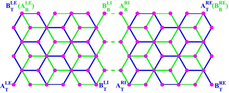
As depicted in Fig. 5, we consider the simplest LSW, i.e., a grain boundary separating BLG into left and right domains. Near the LSW, the lattices are continuous in one layer but fractured along a zigzag edge in the other. This introduces additional zigzag boundaries in the broken layer and allows switching of the bulk stacking order from  (
( ) on the left to
  (
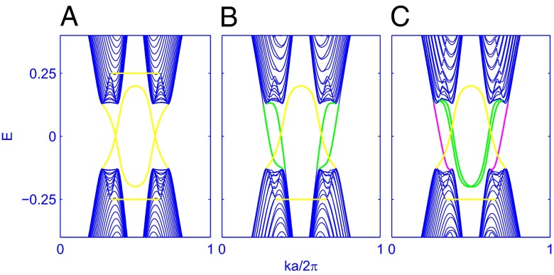
( ) on the right. For comparison, we first calculate the band structures for the case of uniform gapped BLG and for the case of gapped BLG with an EFW at which stacking order is preserved. As expected and shown in Fig. 6 A and B, quantum valley Hall edge states (13) and two flat bands appear at the outer zigzag edges in uniformly gapped BLG. In the sample with an EFW, there is an additional pair of copropagating chiral gapless modes, which emerge at each valley. Fig. 6C shows the situation for a LSW with a uniform interlayer electric field; surprisingly, there are three instead of two gapless modes per valley in this case.
Fig. 5.
The simplest LSW separating BLG into a left (L) domain with  stacking (
 ) and a right (R) domain with
  stacking (
 ). When the BLG is uniformly gapped, gapless modes emerge along the outer zigzag edges (E) as well as along the LSW interfaces (I). The lattices are continuous in the bottom (B) layer but have a straight crack in the top (T) layer. The dashed lines denote the tunneling between the domains within the continuous layer.
Fig. 6.
Gapless modes for (A) uniform gapped BLG, for (B) gapped BLG with an EFW, and for (C) gapped BLG with a LSW as depicted in Fig. 5. The yellow states localize on the outer zigzag boundary and they are doubly degenerate in B and C. The green states localize on the EFW in B and on the LSW in C. In C, the green (magenta) LSW states localize on the broken (continuous) layer. To illustrate these different cases, we chose the following parameter values:  ,
,  , and
, and  .
.
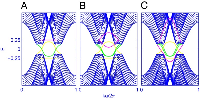
We investigate this problem further by studying the dependence on the tunneling amplitude  across the LSW shown as the dashed lines in Fig. 5. Without tunneling (Fig. 7A), the boundary mode spectrum yields two copies of the gapped BLG spectrum shown in Fig. 6A, and thus there are two chiral gapless modes in each valley as anticipated by the continuum model. The flat bands represent the states localized on the grain boundary lines
  and
and  in Fig. 5. The leading effect of turning on the tunneling is that the pair of degenerate flat bands (magenta bands in Fig. 7) are split and become dispersive, as described in Fig. 7 B and C. When the tunneling is larger than the electric field induced gap, the flat band split downward is pushed down to the valence band and becomes the third gapless mode shown in Fig. 6C.
Fig. 7.
Evolution of gapless modes for gapped BLG as a function of hybridization across the LSW. The tunneling parameter  is, respectively, 0 in A, 0.2 in B, 0.6 in C, and 1 in Fig. 6C. The other parameters have the same values as in Fig. 6. In A, all of the yellow, green, and magenta states are doubly degenerate.
The other two gapless modes (green bands in Fig. 7) localized on the grain boundary of the broken layer are almost degenerate due to the inversion symmetry between the lines  and
and  in Fig. 5. This degeneracy is exact at
  and can be lifted by breaking the inversion symmetry between the left and right domains. We further find that a local potential
  on
on  or
or  can raise and lower the energies of the green bands. Similarly, a line potential on
  or
or  can change the energies of the magenta bands. In view of these results we propose a criterion controlled by a hierarchy of energy scales to determine the number of fragile gapless modes in the atomically abrupt LSW shown in Fig. 5:
 |
 |
where  is one-half size of the field-induced gap, which saturates if V exceeds a critical value (6). As described in Fig. 7A, the two green bands are independent of
  and connect the two valleys at energy of
  . When a positive (negative)
  on
on  or
or  is turned on, the corresponding green band will respond by shifting in energy. Eq. 12 is therefore the condition for the appearance of this gapless channel. The two magenta bands also connect the two valleys and become flat at energy
  when
when  . Turning on
  will lift their degeneracy and pin their energies to
  at
at  . As in the case for green bands, a positive (negative)
  on
on  or
or  could move one magenta band upward (downward) whose emergence in the gap is related to fulfilling Eq. 13.
When the LSW is made smooth in the sense that it does not produce sufficiently strong intervalley coupling, the tunneling amplitudes near the domain wall in both layers are almost the same as the pristine ones. In such a case, the tunneling between the left and right domains in the broken (continuous) layer would strongly split the two green (magenta) bands at  . As a result, only one green and one magenta bands in Fig. 7 survive in the band gap, recovering our earlier continuum results.
Discussion
This article provides a general framework for understanding valley-projected chiral domain wall modes in BLG and their fate in the presence of possible lattice-scale potentials that acts to recouple states in the two valleys. We conclude that gapless interface modes at a LSW are topologically stable when the potential difference between layers is the dominant energy scale and the valley index can be regarded as a good quantum number. In this case, the valley Chern number provides a useful index for interpreting the valley-projected spectra. Domain walls where the electric field is reversed and where the layer stacking is reversed each induce phase twists in the manifold of occupied states, which, although distinct in these two situations, confine pairs of valley-projected chiral modes in the domain wall. Interestingly, even in the valley-projected problem, these modes can be gapped by their interaction within defects where both the perpendicular field and stacking order are allowed to vary in space. Furthermore, the topological protection of the domain wall modes can be preempted entirely by sufficiently strong lattice-scale physics. In this situation, the valley Chern number no longer characterizes the spectral properties and in the general case the number of domain wall modes can be any integer from 0 to 4 depending on the criteria like that implied by Eqs. 12 and 13. The valley-projected topological-state analysis of BLG is illustrative of similar physics that occurs in all chiral multilayer graphene systems (6, 13) and is sensitive to stacking order, and to perpendicular electric fields.
ABA-ABC stacking domain walls are occasionally obtained in exfoliated trilayer graphene samples (20) and similar LSWs in bilayer and thicker chiral graphene are also experimentally accessible. A key difference is that the weak topological invariant (valley Chern number) cannot be defined on the ABA trilayer domain where the system is not gapped (20) even under a large perpendicular electric field. LSWs can be imaged by transmission electron microscopy, visualized by optical microscopy, and probed by scanning tunneling microscopy (STM) and transport experiments. When the STM tip crosses the LSW, sharp field-induced features in the local density of state at the gap edges should be suppressed due to the dispersive domain wall modes. In the presence of a perpendicular electric field, the conductance in a sample with a single LSW depends very sensitively on the orientation of the sample and on the positions of the contacts. Along a LSW, the Landauer conductance, in the absence of intervalley scattering, may reach  , where N is the number of nearly perfect transmission channels (17) in each valley. In a sample with many LSWs or with strong intervalley scattering, the conductance may be much smaller than
  due to backscattering within and between the LSWs.
Note Added in Proof.
After the completion of this work, a complementary preprint (21) and an experimental study (22) which cover closely related material have appeared.
Acknowledgments
This work is supported by Defense Advanced Research Planning Agency under Grant SPAWAR N66001-11-1-4110, by the Department of Energy, Office of Basic Energy Sciences, under Contract DE-FG02-ER45118, and by The Welch Foundation Grant TBF1473.
Footnotes
The authors declare no conflict of interest.
References
- 1.Min H, MacDonald AH. Chiral decomposition in the electronic structure of graphene multilayers. Phys Rev B. 2008;77:155416. [Google Scholar]
- 2.McCann E, Fal’ko VI. Landau-level degeneracy and quantum Hall effect in a graphite bilayer. Phys Rev Lett. 2006;96(8):086805. doi: 10.1103/PhysRevLett.96.086805. [DOI] [PubMed] [Google Scholar]
- 3.Ohta T, Bostwick A, Seyller T, Horn K, Rotenberg E. Controlling the electronic structure of bilayer graphene. Science. 2006;313(5789):951–954. doi: 10.1126/science.1130681. [DOI] [PubMed] [Google Scholar]
- 4.Oostinga JB, Heersche HB, Liu X, Morpurgo AF, Vandersypen LMK. Gate-induced insulating state in bilayer graphene devices. Nat Mater. 2008;7(2):151–157. doi: 10.1038/nmat2082. [DOI] [PubMed] [Google Scholar]
- 5.Castro EV, et al. Biased bilayer graphene: Semiconductor with a gap tunable by the electric field effect. Phys Rev Lett. 2007;99(21):216802. doi: 10.1103/PhysRevLett.99.216802. [DOI] [PubMed] [Google Scholar]
- 6.Zhang F, Sahu B, Min H, MacDonald AH. Band structure of ABC-stacked graphene trilayers. Phys Rev B. 2010;82:035409. [Google Scholar]
- 7.Zhang F, Min H, Polini M, MacDonald AH. Spontaneous inversion symmetry breaking in graphene bilayers. Phys Rev B. 2010;81:041402. [Google Scholar]
- 8.Feldman BE, Martin J, Yacoby A. Broken-symmetry states and divergent resistance in suspended bilayer graphene. Nat Phys. 2009;5:889–893. [Google Scholar]
- 9.Martin J, Feldman BE, Weitz RT, Allen MT, Yacoby A. Local compressibility measurements of correlated states in suspended bilayer graphene. Phys Rev Lett. 2010;105(25):256806. doi: 10.1103/PhysRevLett.105.256806. [DOI] [PubMed] [Google Scholar]
- 10.Velasco J, Jr, et al. Transport spectroscopy of symmetry-broken insulating states in bilayer graphene. Nat Nanotechnol. 2012;7(3):156–160. doi: 10.1038/nnano.2011.251. [DOI] [PubMed] [Google Scholar]
- 11.Bao W, et al. Evidence for a spontaneous gapped state in ultraclean bilayer graphene. Proc Natl Acad Sci USA. 2012;109(27):10802–10805. doi: 10.1073/pnas.1205978109. [DOI] [PMC free article] [PubMed] [Google Scholar]
- 12.Martin I, Blanter YM, Morpurgo AF. Topological confinement in bilayer graphene. Phys Rev Lett. 2008;100(3):036804. doi: 10.1103/PhysRevLett.100.036804. [DOI] [PubMed] [Google Scholar]
- 13.Zhang F, Jung J, Fiete GA, Niu Q, MacDonald AH. Spontaneous quantum Hall states in chirally stacked few-layer graphene systems. Phys Rev Lett. 2011;106(15):156801. doi: 10.1103/PhysRevLett.106.156801. [DOI] [PubMed] [Google Scholar]
- 14.Xiao D, Chang MC, Niu Q. Berry phase effects on electronic properties. Rev Mod Phys. 2010;82:1959–2007. [Google Scholar]
- 15.Li J, Morpurgo AF, Büttiker M, Martin I. Marginality of bulk-edge correspondence for single-valley Hamiltonians. Phys Rev B. 2010;82:245404. [Google Scholar]
- 16.Li J, Martin I, Buttiker M, Morpurgo AF. Topological origin of subgap conductance in insulating bilayer graphene. Nat Phys. 2011;7:38. [Google Scholar]
- 17.Qiao Z, Jung J, Niu Q, Macdonald AH. Electronic highways in bilayer graphene. Nano Lett. 2011;11(8):3453–3459. doi: 10.1021/nl201941f. [DOI] [PubMed] [Google Scholar]
- 18.Jung J, Zhang F, Qiao Z, MacDonald AH. Valley-Hall kink and edge states in multilayer graphene. Phys Rev B. 2011;84:075418. [Google Scholar]
- 19.Zarenia M, Pereira JM, Jr, Farias GA, Peeters FM. Chiral states in bilayer graphene: Magnetic field dependence and gap opening. Phys Rev B. 2011;84:125451. [Google Scholar]
- 20.Zou K, Zhang F, Clapp C, MacDonald AH, Zhu J. Transport studies of dual-gated ABC and ABA trilayer graphene: Band gap opening and band structure tuning in very large perpendicular electric fields. Nano Lett. 2013;13(2):369–373. doi: 10.1021/nl303375a. [DOI] [PubMed] [Google Scholar]
- 21.Vaezi A, Liang Y, Ngai DH, Yang L, Kim E. 2013. Topological kink states at a tilt boundary in gated multilayer graphene. arXiv:1301.1690.
- 22.Alden JS, et al. 2013. Strain solitons and topological defects in bilayer graphene. Proc Natl Acad Sci USA, 10.1073/pnas.1309394110.


