

Abstract
The characteristics of transcranial magnetic stimulation (TMS) pulses influence the physiological effect of TMS. However, available TMS devices allow very limited adjustment of the pulse parameters. We describe a novel TMS device that uses a circuit topology incorporating two energy storage capacitors and two insulated-gate bipolar transistor (IGBT) modules to generate near-rectangular electric field pulses with adjustable number, polarity, duration, and amplitude of the pulse phases. This controllable pulse parameter TMS (cTMS) device can induce electric field pulses with phase widths of 10–310 μs and positive/negative phase amplitude ratio of 1–56. Compared to conventional monophasic and biphasic TMS, cTMS reduces energy dissipation by up to 82% and 57%, and decreases coil heating by up to 33% and 41%, respectively. We demonstrate repetitive TMS trains of 3,000 pulses at frequencies up to 50 Hz with electric field pulse amplitude and width variability less than the measurement resolution (1.7% and 1%, respectively). Offering flexible pulse parameter adjustment and reduced power consumption and coil heating, cTMS enhances existing TMS paradigms, enables novel research applications, and could lead to clinical applications with potentially enhanced potency.
1. Introduction
Transcranial magnetic stimulation (TMS) involves the delivery to the brain of brief, high intensity magnetic pulses that induce an electric field to modulate neural activity. The magnetic field is generated by high amplitude current pulses delivered to a coil placed on the head. TMS is used as a non-invasive tool for studying the brain, an approved treatment for depression, and an investigational treatment for other psychiatric and neurological disorders.
Available TMS devices induce damped cosine electric field pulses. The pulse amplitude can be adjusted over a wide range; however, there is non-existent or very limited control over other pulse parameters such as the polarity, number, duration, and relative amplitude of the individual phases constituting the electric field pulse [1–4]. These characteristics of the induced electric field affect the neural response and, consequently, the behavioral, cognitive, and clinical effects of TMS. Devices for in vitro magnetic neural stimulation that allow more extensive control of the pulse parameters have been developed [5], but their output is orders of magnitude weaker than that required for TMS. We previously reported on a TMS device that induces near rectangular electric field pulses with pulse width controllable over a wide range [6]. We have now extended this controllable pulse parameter TMS (cTMS) technology to allow adjustment of the polarity, number, duration, and relative amplitude of the phases of the electric field pulse. Further, this novel cTMS device has lower power consumption and coil heating than conventional devices and allows efficient generation of high frequency pulse trains that are used in repetitive TMS (rTMS). The unparalleled flexibility and efficiency of the cTMS device could enable optimization of clinical and research TMS and rTMS paradigms as well as the development of novel applications.
As previously reported, the pulse width adjustment feature of cTMS can be used to derive neural strength–duration curves and membrane time constants, and to differentially target neural populations with distinct time constants [6]. The effect of pulse width on neural response in the brain, scalp, and peripheral nerves has not been fully explored due to the difficulty in modifying pulse width in conventional TMS machines [4,7].
In addition to these applications, the novel cTMS device presented here can generate pulses that have significantly larger amplitude of the positive electric field phase relative to the negative phase (predominantly unidirectional pulses). cTMS can induce predominantly unidirectional electric fields with both monophasic and biphasic magnetic pulses by setting different magnetic field rise and fall slopes. In contrast, predominantly unidirectional electric field pulses are traditionally generated by monophasic TMS devices whose output is curbed at high frequencies due to the use of an inefficient circuit topology [1]. There is mounting evidence that rTMS with predominantly unidirectional pulses may have a stronger and more selective neuromodulatory effect than conventional rTMS with bidirectional pulses [8–14]. Thus, the capability of cTMS to efficiently induce electric field pulses with a wide range of directionality (ratio of positive to negative electric field phase amplitude) could enable the development of more selective and potent neuromodulation paradigms.
Finally, cTMS requires less energy to stimulate neurons and produces less coil heating than conventional TMS, as shown in [6] and in this work. Traditional monophasic and biphasic TMS circuits inefficiently transfer energy from the capacitor to the coil due to the decay of the capacitor voltage over the pulse duration [6]. In contrast, the cTMS topology maintains high capacitor voltage throughout the pulse duration, providing efficient energy transfer to the coil. Furthermore, conventional TMS devices generate damped sine coil current, whereas it has been theoretically shown that for a first-order neural membrane model, rising-exponential coil current pulses are most energy efficient [15].‡ The approximately triangular coil current generated by cTMS is closer to a rising exponential than conventional sine pulses. The reduced power consumption and coil heating in the cTMS device could benefit high frequency, high power TMS applications such as rTMS and magnetic seizure therapy (MST) [17].
In this paper we describe the circuit topology and implementation of the extended functionality cTMS device. We also present data on the induced electric field pulse shape and parameter adjustablility, energy use and coil heating, and reliability of the device operation at high frequencies. This work was previously presented in part in conference proceedings [18].
2. Device design
2.1. Circuit topology
The topology of the extended functionality cTMS device is shown in figure 1. Capacitor C1 is charged to a positive voltage VC1 and capacitor C2 is charged to a negative voltage VC2 by the power supply. During the TMS pulse, the stimulation coil L is connected to one of the two energy storage capacitors, C1 or C2, via current-bidirectional switches, Q1/D1 or Q2/D2, respectively. Unlike the silicon-controlled rectifiers used in conventional TMS devices, which conduct until the coil current drops to zero, IGBTs can be turned off via the gate terminal, enabling electronic control of the pulse duration. The electric field strength induced by the TMS coil is proportional to the voltage applied across L. This effect can be thought of in terms of an electrical transformer realized between the TMS coil (primary winding) and the head tissue (secondary winding). The electric field can therefore be made positive or negative by connecting L to C1 or C2, respectively. Furthermore, the beginning and duration of the electric field pulse phases can be controlled by the timing of switches Q1 and Q2. The operator can thus control the electric field temporal parameters by adjusting the capacitor voltages VC1 and VC2 and the conduction time of switches Q1 and Q2.
Figure 1.
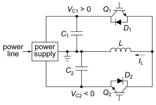
Controllable pulse parameter TMS (cTMS) circuit topology.
To elucidate the cTMS circuit operation, we consider the case when capacitances C1 and C2 are large and the circuit parasitics can be ignored. In this case, the cTMS topology induces electric field pulses with close to rectangular shape. In particular, this is true if the duration of the positive and negative electric field phases is much shorter than the resonance quarter periods and , respectively. Figure 2 illustrates the operation of the circuit for VC1 : VC2 = 5 : 1, in the limit of infinite capacitances where capacitors C1 and C2 can be thought of as constant voltage sources. Figure 2(a) depicts the generation of a pulse of positive coil current, IL. Switch Q1 is turned on, resulting in IL increasing linearly at a rate of dIL/dt = VC1/L. By Ampère’s law the magnetic field B induced by the coil is proportional to IL, and by Faraday’s law the induced electric field E is proportional to the magnetic field rate of change and, hence, to dIL/dt. Since C1 is very large, VC1 stays approximately constant. While Q1 is on, energy is transfered from C1 to L, where ILpk is the peak coil current. When the controller turns off Q1, the coil current is forced to commutate to C2 via diode D2, because the inductor current IL is continuous and cannot be interrupted. Since a negative voltage VC2 is now applied across the coil, IL starts to collapse at a rate of dIL/dt = VC2/L, transferring the coil energy to C2. When IL decays to zero, D2 turns off, ending the pulse. Thus, the duration of the last electric field phase is determined by the constraint that the coil current must go to zero. Generally, the coil current has to decay to zero since it is not practically feasible to sustain continuous currents at the kiloampere levels deployed in TMS. Therefore, the integral of dIL/dt evaluates to zero and, consequently, the total area under the positive phases of the electric field pulse has to equal the total area under the negative phases (i.e., the current pulses induced in the tissue are charge balanced).
Figure 2.

Example cTMS pulses assuming large capacitances C1 and C2: (a) positive monophasic, (b) negative monophasic, and (c) biphasic with initial negative phase. The “don’t care” switch states indicate when a switch can be gated either on or off without affecting the circuit operation.
Analogously to the positive pulse, a negative magnetic pulse can be generated by turning on Q2 as shown in figure 2(b). In this case, energy is first transferred from C2 to L while Q2 is on, and then that energy is transferred from L to C1 while D1 is on. Magnetic pulses with multiple phases can be generated by appropriate gating of Q1 and Q2. For example, figure 2(c) shows a biphasic magnetic pulse and the associated triphasic electric field pulse obtained by following the negative pulse from 2(b) with the positive pulse from 2(a). Here, energy is transfered from C2 to L to C1 to L and finally back to C2, resulting in energies in the two capacitor that are identical to those before the pulse initiation.
Ignoring power loss due to component non-idealities and auxiliary circuits, the topology in figure 1 is fundamentally lossless since during TMS pulses energy is not dissipated but is transferred between the capacitors C1 and C2 via the coil L. In reality, conduction and switching losses result in energy dissipation during each pulse. Nevertheless, a substantial portion of the energy is recovered on the capacitors at the end of the pulse, analogously to the operation of conventional biphasic rTMS devices [1]. The recovered energy can be reused in subsequent pulses, enabling energy efficient operation that is particularly relevant to rTMS applications where pulse trains may be delivered at high frequencies (> 1 Hz). To reuse the energy of pulses that result in net energy transfer from one capacitor to the other, such as those in figure 2(a,b), the power supply should be designed to allow energy transfer not only from the power line to the capacitors, but also between the two capacitors. On the other hand, pulses that do not result in net energy transfer, such as the biphasic pulse in figure 2(c), can reuse the returned pulse energy without capacitor energy transfer through the power supply.
Another reason for increased energy efficiency of the cTMS device is that the triangular magnetic pulses and the associated rectangular electric field pulses provide more efficient neural stimulation than conventional cosine TMS pulses, as discussed in section 1. To generate rectangular electric field pulses, C1 and C2 have to be larger than the capacitors used in conventional TMS devices. Besides near-rectangular electric field pulse shape, the larger capacitors enable a wide range of pulse width control.
In summary, the cTMS topology shown in figure 1 allows independent control of the amplitude of the positive and negative phases of the electric field pulse via capacitor voltages VC1 and VC2, respectively, as well as control of the width of the electric field phases via the timing of switches Q1 and Q2. The pulse generation is inherently efficient since the pulse energy is recovered on the capacitors at the end of the pulse.
2.2. Circuit implementation
The key features of our circuit implementation of the cTMS topology are shown in figure 3, and the corresponding component data are given in table 1. All system components except for the TMS coil were installed in a grounded aluminum and steel enclosure (P/N AGR-9542-RB, Bud Industries, Inc., Willoughby, OH).
Figure 3.

Simplified schematic of cTMS power train implementation.
Table 1.
Key cTMS Power Train Components
| Component | Function | Rating | Part # | Manufacturer |
|---|---|---|---|---|
| C 1 | energy storage | 370/740 μF, polypropylene film | (2/4) 39738 | General Atomics |
| C 2 | energy storage | 1,500/3,000 μF, polypropylene film | (1/2) 700D158915-199* | SB Electronics |
| Q1/D1, Q2/D2 | IGBT coil switche | 900 Adc, 4.5 kV | CM900HB-90H | Powerex |
| GD1, GD2 | IGBT gate drive | VGE = −6 V (off), 20 V (on) | AP-1318* | APS |
| L | stimulation coil | L ≥ 8 μH, ∣IL∣ ≤ 7 kA | various | various |
|
| ||||
| R3, R4 | IGBT turn-off snubber | 0.5 Ω, non-inductive | (2) NHL-20-02Z | Vishay Dale |
| C3, C4 | IGBT turn-off snubber | 1 μF, polyester film | (2) 45PC113* | SB Electronics |
| C5, C6 | IGBT turn-off snubber | 0.5 μF, polyesther film | 45PC113* | SB Electronics |
| R 5 | coil snubber | 0.67 Ω, non-inductive | (3) NH0502R000FC02 | Vishay Dale |
| Q3/D3, Q4/D4 | coil snubber switch | 3.4 kV (2 in series), 75 A | (2) IXGX32N170H1 | IXYS |
|
| ||||
| PS 1 | capacitor C1 charger | 3 kV, 1 kW | 102A-3KV-POS | Lambda |
| PS 2 | capacitor C2 charger | −1.5 kV, 1 kW | 102A-1.5KV-NEG | Lambda |
|
| ||||
| ctrl | digital controller | 0.1 μs pulse timing resolution | cRIO-9014 | National Instruments |
custom manufactured or modified
2.2.1. Power supply and energy storage
The energy storage capacitors C1 and C2 are charged by power supplies PS1 and PS2, respectively, that are connected to the power line (115 Vac). The default configuration of the device is with C1 = 370 μF and C2 = 1,500 μF, but the capacitances can be doubled by connecting an extra set of capacitors. Capacitor voltages VC1 and VC2 can be set in the range of 100 to 2,800 V and −50 to −1,000 V, respectively, resulting in maximum positive/negative phase amplitude ratio of the induced electric field pulses of 2,800/50 = 56. The capacitor voltage difference is limited by the controller to VC1 − VC2 ≤ 3.4 kV to prevent damage to the IGBT switches Q1 and Q2 which have a maximum collector–emitter voltage rating of 4.5 kV (the 1.1 kV safety margin accommodates transient voltage spikes due to parasitic inductances during switching). In the present cTMS device implementation, the power supplies are designed to transfer energy only from the power line to the storage capacitors. A dc–dc converter to transfer energy between the two capacitors could be added to enable efficient monophasic magnetic pulse trains (see also section 4.3). Relays S1 and S2 and resistors R1 and R2 are used to discharge capacitors C1 and C2, respectively, when the capacitor voltages have to be reduced without delivering a pulse to L.
Capacitances C1 and C2 are, respectively, 2–7 times and 8–30 times larger than conventional TMS capacitors. The reason for using large capacitance values in cTMS is that they enable near rectangular electric field pulses with a wide range of pulse width adjustment. In this implementation, C2 is 4 times larger than C1 in order to allow the generation of predominantly unidirectional electric field pulses (large-amplitude, short-duration positive electric field phase and low-amplitude, long-duration negative electric field phase) which are of interest for optimizing TMS selectivity and rTMS neuromodulatory potency. The reason for implementing relatively high capacitor voltages is to allow suprathreshold stimulation with very brief electric field pulse widths (down to pulse phase duration of ~20 μs) which enable derivation of strength-duration curves, control of stimulation selectivity, and pulse energy optimization. The combination of large capacitances and high capacitor voltages can result is large stored energy. Safety and device size considerations limit the practical size of the cTMS energy storage capacitors and, hence, the maximum pulse width (see also section 4.2).
2.2.2. Power switches
Switches Q1/D1 and Q2/D2 are implemented with IGBT modules rated at 4.5 kV and 900 Adc. The current rating of the IGBT modules is below the peak current of ≤ 7 kA occurring in the cTMS switches under normal operating conditions. The rationale for this design choice is that the IGBTs can handle currents of over 10 times their rating in brief pulses and when the transistor is paralleled with a snubber as long as the semiconductor junction temperature does not exceed 125°C [19–22] (see also discussion in sections 2.2.3 and 4.3). The two IGBT modules were mounted on a single heat sink with dimensions 39 cm × 14 cm × 5.1 cm (P/N 64315, Aavid Thermalloy, LLC, Concord, NH) with 1.8 m/s forced air flow. The IGBT cooling was designed to limit the IGBT junction temperature below 90°C even under extreme load (100 Hz pulse train, 7 kA peak current, 400 μs pulse width).
The IGBT gate emitter voltage in on state was driven to 20 V, the maximum specified for this IGBT, to provide low collector–emitter voltage drop. Pulse width limits and short circuit protection were implemented in the controller and the IGBT drives to prevent Q1 and Q2 from turning on at the same time, which would short C1 and C2, and to preclude long pulse widths that would result in excessive coil current or would discharge and reverse the polarity of C1 or C2. The presence of “don’t care” states, shown in figure 2, relaxes the requirements on the timing precision of switches Q1 and Q2 during current commutation, such as during the positive electric field phase of the biphasic pulse in figure 2(c). In that case, Q1 can be turned on at any point between the time Q2 is turned off and IL reaches zero.
2.2.3. Snubbers
IGBT snubbers comprised of C3–C6, R3, and R4 serve the dual purpose of taking over a portion of the IGBT current during turn-off and suppressing high-amplitude ringing of the IGBT collector–emitter voltage due to parasitic inductances [6,20,21,23]. The total capacitance of C3–C6, 3 μF, was chosen to take over a significant portion of the IGBT current during the IGBT turn off transition (~ 1 μs). The parasitic inductance in series with the IGBTs was measured to be around 0.15 μH. IGBT snubber designs using diodes, deployed in our previous cTMS report [6], were only partially effective since the forward recovery time of the diodes (~ 0.3 μs) resulted in significant overshoot and ringing of the IGBT collector–emitter voltage during turn-off. Therefore, purely passive snubbers were used in this design, with R3 and R4 selected to dampen ringing caused by the parasitic inductance [24, 25]. The IGBT gate drives, GD1 and GD2, were designed to provide slow IGBT turn on to limit current in the snubbers (10 Ω gate resistance) and fast turn off to reduce energy dissipation in the IGBT and allow the snubbers to take over the IGBT current (4 Ω gate resistance). In addition to using snubbers, the power train components and interconnects were laid out so as to minimize the parasitic inductance of the high current paths. Collectively, the minimization of parasitic inductance and the use of snubbers reduce the likelihood of damage to the IGBTs during the turn-off transition.
The total capacitance between the emitter and collector of Q1 and Q2, including the passive snubber capacitance, would resonate with the coil L at the end of the cTMS pulse, resulting in a long underdamped sinusoidal tail. This behavior is an undesirable feature of the pulse shape and produces additional coil heating and electromagnetic noise. The ringing can be suppressed by adding another snubber in parallel with L. If this additional snubber is realized with a series resistor and capacitor, the capacitance has to be twice the existing capacitance seen across the coil [25], which would be 6 μF for this design. This additional capacitance would triple the switching losses associated with the snubbers. Therefore, we implemented an active snubber consisting of Q3/D3, Q4/D4, and R5 that turns on only at the end of the pulse. The active snubber is operated so that its gating is not very sensitive to the duration of the cTMS pulse. If the last phase of the pulse applies a negative voltage across L (D2 is on) as in figure 2(a,c), Q3 can be activated with some delay after Q1 has been turned off (and D2 is conducting). When the coil current drops to zero, D2 turns off and the coil will start a resonant oscillation with the passive snubber capacitance. When the coil voltage becomes positive during the oscillation, the active snubber will start conducting via Q3 and D4, connecting resistor R5 in parallel with the coil and, consequently, damping the oscillation. Analogously, if the last phase of the cTMS pulse applies a positive voltage across L (D1 is on) as in figure 2(b), Q4 should be activated with some delay after Q2 has been turned off. This will suppress the oscillation when the coil voltage swings negative. Note that with this active snubber control scheme, the precise timing of Q3 or Q4 turn-on is not critical as long as it is during the last phase of the cTMS pulse.
2.2.4. Coil
cTMS can operate with both air-core and ferromagnetic-core coils, as long as the inductance is not too low (L ≳ 10 μH), heavy saturation is avoided in ferromagnetic-core coils, and the coil can sustain the maximum voltage and energy delivered by the cTMS device. By providing electronic control over the pulse width via the gating of the IGBT switches, the cTMS topology makes the pulse width largely independent of the coil inductance L; although L in conjunction with the capacitance values C1 and C2 still determines the maximum possible pulse width. Thus, in cTMS the coil determines the spatial distribution of the electric field, whereas the capacitor voltages and IGBT timing determine the temporal waveform of the electric field pulse.
2.2.5. Controller
The cTMS controller (ctrl) was implemented around a cRIO real-time controller (National Instruments Corp., Austin, TX). The cRIO integrates a conventional microprocessor, a field-programmable gate array, and isolated analog and digital input/output modules. The field-programmable gate array provides precise timing with a 0.1 μs resolution for the power train switches (Q1–Q4, S1, and S2). The analog and digital input/output modules interface to the power train via custom signal conditioning and protection circuits. The cRIO controller is programmed through a connection to a laptop running a LabVIEW (National Instruments Corp.) graphical user interface.
3. Results
3.1. Pulse characteristics
We recorded the coil current and electric field of cTMS and conventional monophasic and biphasic TMS devices (respectively, Magstim 200 and Magstim Rapid, Magstim Co., Whitland, UK) with figure-8 coils with air core (P/N 9925-00, Magstim Co.) and ferromagnetic core (CRS 2100, Neuronetics, Inc., Malvern, PA). The coil current and electric field were measured with a Rogowski current probe (CWT 30B, Power Electronic Measurements Ltd., Beeston, UK) and a search coil, respectively. The search coil was made of a single-turn rectangular winding with dimensions 1 cm × 30 cm, positioned perpendicular to the TMS coil plane, with one of the 1 cm sides standing 1 mm away from the TMS coil center, parallel to the electric field orientation [26]. The search coil outputs voltage approximately equal to the electric field in V/cm [26]; however, the exact calibration of the search coil output is irrelevant, as long as its position relative to the TMS coil is accurately replicated for each measurement. For this purpose, the search coil was rigidly attached to each of the TMS coils.
Figure 8.

Comparison of conventional TMS and cTMS pulse configurations for (a) energy delivered to coil, (b) dissipated energy, and (c) coil temperature rise. See definitions in section 3.2.1 and in figure 4.
To allow comparison of neural stimulation efficiency among the various pulse shapes, the resulting neural depolarization was estimated with a low-pass filter with 150 μs time constant connected to the search coil; the filter output approximates the subthreshold dynamics of the neural membrane potential [7].
3.1.1. Pulse shape
Three example cTMS pulses are compared to conventional TMS pulses in figure 4 which shows the coil current, induced electric field, and estimated membrane potential change. The amplitudes of all TMS pulses were adjusted to produce estimated neural depolarization equal to that induced by the Magstim 200 at 50% of its maximum pulse amplitude, corresponding to approximately 120% of average motor threshold [27] (stimulation strength of 120% motor threshold is commonly used in therapeutic applications [28]). The equal depolarization associated with the various pulses can be seen in the rightmost column of figure 4 where all the waveforms have the same peak level (arbitrarily assigned to unity).
Figure 4.

Comparison of cTMS pulses (mRec, bRec1, bRec2) with conventional sinusoidal TMS pulses (mCos, bCos). Pulse configurations mCos and bCos are generated by Magstim 200 and Magstim Rapid, respectively. Shown are measured TMS coil current (left), induced electric field (center), and estimated neural membrane potential change (right) for monophasic (top two rows) and biphasic (bottom two rows) pulses delivered through figure-8 coils with air core (rows 1 and 3) and ferromagnetic core (rows 2 and 4). The electric field was measured with a search coil, and the neural membrane dynamics was estimated by low-pass filtering the search coil output with a 150 μs time constant. The capacitor voltages (given on the right) were set so that the estimated neural depolarization is the same for all pulses, corresponding to that produced by Magstim 200 at 50% of maximum pulse amplitude (that depolarization level is arbitrarily assigned to unity). Further detail on the measurement setup is provided in section 3.1.
Figure 4 demonstrates that the cTMS pulses (mRec, bRec1, and bRec2) have a more rectangular electric field waveform and a more triangular coil current (and hence magnetic field) waveform than conventional TMS pulses (mCos and bCos). The low-amplitude, exponentially-decaying phase at the end of the cTMS pulses results from discharging of the snubbers. This feature is also present in conventional biphasic TMS devices, as seen in the bCos waveform in figure 4 (g–l). The sharp spikes visible in the cTMS electric field waveforms during transitions between positive and negative phases originate from the commutation of the peak coil current between the two energy storage capacitors and the respective IGBT modules in the presence of parasitic inductances and finite switch turn-on times. These spikes are limited by the passive IGBT snubbers, as discussed in section 2.2.3.The spike size can be reduced further by decreasing the parasitic inductances and/or increasing the snubber capacitances.
3.1.2. Pulse parameter control
The parameters of the cTMS pulses can be adjusted over a wide range, as illustrated in figure 5. Specifically, cTMS allows control of the electric field pulse width [figure 5(a,b,e,f,i,j)] and directionality [figure 5(c,d,g,h,k,l)] for both monophasic [figure 5(a–h)] and biphasic [figure 5(i–l)] magnetic pulses. The range of pulse parameter adjustment is constrained by the energy storage capacitor discharge, maximum capacitor voltages, and maximum coil current.
Figure 5.

cTMS pulse parameters can be adjusted over a wide range. Shown are coil current (left) and electric field (right) corresponding to positive monophasic (a-d), negative monophasic (e-h), and biphasic (i-l) pulses with controllable pulse width (a,b,e,f,i,j) and directionality (c,d,g,h,k,l).
In figure 4 and figure 5 we illustrate only monophasic and biphasic magnetic pulses. However, the cTMS device is also capable of generating polyphasic pulses by appropriately gating switches Q1 and Q2; the number of phases and their amplitude and duration would be limited by the gradual discharge of the capacitors due to circuit losses.
3.1.3. Effect of energy storage capacitance
To illustrate the effect of the energy storage capacitor size on the pulse shape, figure 6 compares the default capacitance configuration (C1 = 370 μF, C2 = 1,500 μF) with the double capacitance configuration (C1 = 740 μF, C2 = 3,000 μF). As expected, in the double capacitance configuration the coil current waveforms are closer to triangular and the electric field waveforms are closer to rectangular than those for the default configuration. Furthermore, the double capacitance configuration increases the maximum achievable pulse width by a factor of . Illustrating the extrema of the pulse width range, figure 7(a,b) shows a very short biphasic pulse (50 μs total duration) and figure 7(c,d) shows a very long pulse (837 μs duration) generated by the double capacitance configuration, representing a pulse width range of 17 fold. The individual electric field phases range in duration from 10 μs to 310 μs. At these extremes, the cTMS pulses appear more sinusoidal than in the pulse width mid-range depicted in figures 4–6, due to the snubber capacitance, for the very short pulses, and due to the energy storage capacitor discharge, for the very long pulses.
Figure 6.

Comparison of coil current and induced electric field for default (C 1 = 370 μF, C2 = 1,500 μF) and double capacitance (C1 = 740 μF, C2 = 3,000 μF) cTMS configurations for identical initial capacitor voltages and IGBT gating. Positive monophasic (a,b), negative monophasic (c,d), and biphasic (e,f) pulses are illustrated.
Figure 7.

Extrema of the cTMS pulse width range with double capacitance configuration(C1 = 740 μF, C2 = 3,000 μF): (a,b) very short biphasic pulse (50 μs total duration), and (c,d) very long biphasic pulse (837 μs total duration). Note the difference in time scales.
3.2. Pulse efficiency
3.2.1. Energy use and coil heating
To characterize the electrical efficiency of cTMS, we evaluated the energy requirement, energy dissipation, and coil heating for the conventional sinusoidal TMS pulses and the representative cTMS pulses shown in figure 4. Monophasic and biphasic sinusoidal pulses were delivered with Magstim 200 and Magstim Rapid, respectively. All pulse amplitudes were adjusted to correspond to the estimated 120% average motor threshold, as in section 3.1. We characterized both the energy that has to be delivered to the coil to produce this depolarization level, ΔWL, and the energy that is lost during the pulse, i.e., the energy that is not recovered back on the energy storage capacitors at the end of the pulse, ΔWC. The peak energy delivered to the coil per pulse was computed from the integral of the power sourced from the respective energy storage capacitor Ci (C1 or C2),
| (1) |
The capacitor voltages were measured with high voltage probes P6015A and P5120 connected to a TPS2014 digitizing oscilloscope (Tektronix, Inc., Beaverton, OR). The energy dissipated per pulse was calculated by subtracting the energy in all n power train energy-storage and snubber capacitors before and after the pulse [6]
| (2) |
The heating at the center of the TMS coil face was measured with an infrared thermometer (Fluke 62 Mini, Fluke Corp., Everett, WA) and with a thermocouple (80TK, Fluke Corp.). The coil temperature was also measured with a pair of integrated circuit sensors (LM35, National Semiconductor Corp., Santa Clara, CA) embedded in the air-core coils and placed in the heat-sink fins of the iron-core coil. The infrared thermometer readings were taken only at the beginning and at the end of the pulse train, whereas the other temperature measurements were taken throughout the train duration. The coil was wrapped in foam and placed in a polystyrene box to prevent any significant heat loss. To estimate the temperature rise from a single pulse, we delivered 300 pulses at a rate of 0.25 Hz, recorded the coil temperature difference before and after the train, and divided the temperature difference by 300.
The results for ΔWL, ΔWC, and coil temperature rise are summarized in figure 8(a–c). We present only the infrared thermometer data, since they were deemed most reliable, being insusceptible to electromagnetic induction artifacts from the TMS coil field, and since the temperature change readings among the three thermometer types were highly correlated (R2’s ≥ 0.89, p’s < 0.017).
Figure 8 demonstrates that cTMS can generate both predominantly unidirectional (mRec, bRec1) as well as bidirectional (bRec2) electric field pulses while using less energy and producing less coil heating than conventional sinusoidal TMS pulses (mCos, bCos). For example, both monophasic (mRec) and biphasic (bRec1) cTMS pulses can produce predominantly unidirectional electric fields while requiring 33% and 64% less energy, dissipating 77% and 82% less energy, and producing 33% and 22% less coil heating, respectively, than the mCos pulse generated by Magstim 200 with air-core coil. This substantial difference demonstrates that cTMS can be used to efficiently generate predominantly unidirectional electric field pulses in high frequency trains without excessive power dissipation and heating which limit conventional monophasic devices. Further, cTMS can also generate bidirectional electric field pulses with higher efficiency than conventional rTMS devices. Figure 8 shows that pulse configuration bRec2 has polarization ratio similar to that of bCos generated by Magstim Rapid with air-core coil (0.80 vs. 0.84, respectively), while requiring 26% less energy, dissipating 53% less energy, and producing 31% less coil heating.
The data in figure 8 also confirm that ferromagnetic-core TMS coils have superior efficiency and lower heating compared to air-core coils [29] for both conventional and cTMS pulses. With the ferromagnetic-core coil, the monophasic cTMS pulse (mRec) requires 31% less energy, dissipates 75% less energy, and produces 15% less coil heating than the conventional monophasic pulse (mCos). The biphasic cTMS pulses (bRec1 and bRec2) require 42–58% less energy, dissipate 51–57% less energy, and produce 41% less coil heating than the conventional biphasic pulse (bCos). The cumulative effect of using efficient cTMS pulses and a ferromagnetic-core coil leads to a remarkable reduction of power dissipation and coil heating of 12 fold and 8 fold, respectively, for predominantly unidirectional electric field pulses (bRec1 with ferromagnetic-core coil vs. mCos with air-core coil).
3.2.2. Strength–duration and energy–duration curves
Finally, the cTMS pulse parameters can be optimized to minimize the required or dissipated energy per pulse. We explored the effect of pulse width on the required capacitor voltages, coil current, and energy for a given level of estimated neural depolarization. These curves were measured for monophasic cTMS pulses similar to mRec in figure 4 using air-core coil. The capacitors were configured at C1 = 740 μF and C2 = 3,000 μF, the capacitor voltage ratio was fixed at VC2 = −0.25VC1, the width of the positive (depolarizing) pulse phase was varied from 10 to 140 μs in 10 μs steps, and the capacitor voltages were adjusted so that the estimated neural depolarization matched that of Magstim 200 at 50% of maximum pulse amplitude (the method for estimating neural depolarization is described in section 3.1). Thus, for each pulse width, the resulting depolarization was the same as that produced by the pulses in figure 4. The 10 μs pulse width point was recorded at the device limit of VC1 = 2,800 V, which resulted in depolarization below the target level (Magstim 200 at 50% of maximum pulse amplitude). To extrapolate the efficiency at that pulse width if the device were modified to allow VC1 > 2,800 V, we proportionally scaled up the capacitor voltage and coil current data so that the estimated depolarization matched the targeted level, and used these data to calculate ΔWL and ΔWC.
Figure 9(a) shows the strength–duration curves linking the initial capacitor voltage VC1(0) and peak coil current ILpk to the pulse width. Figure 9(b) shows the energy–duration curves for the energy delivered to the coil ΔWL and the energy lost per pulse ΔWC, calculated by equations (1) and (2), respectively. The 10 μs pulse width point is shown with a dashed line since it is extrapolated as described above. As expected [6,7], the capacitor voltage increases for brief pulse widths, whereas the coil current grows for long pulse widths. The magnetic field energy, proportional to , monotonically decreases as the pulse width decreases, but the energy delivered to the coil starts to increase below pulse width of 20 μs. Thus, even though briefer pulses require less energy to stimulate neurons, for pulses shorter than 20 μs the energy necessary for stimulation starts to increase. This increase in the energy requirement likely stems from increased switching losses in the snubbers and parasitic capacitances due to the exponential rise of the capacitor voltage. Another contributor to increased dissipation at brief pulse widths may be higher skin-effect and proximity-effect losses in the coil due to the higher frequency components of the coil current (for a ferromagnetic-core coil, core losses may also increase). The least energy dissipation occurs at pulse width of 40 μs, which would produce the minimum power consumption in rTMS where the energy delivered to the coil minus the dissipated energy is recycled.
Figure 9.

Measured strength–duration (a) and energy–duration (b) curves for a monophasic cTMS pulse. The abscissa gives the duration of the depolarizing phase of the electric field pulse. Panel (a) shows the initial capacitor voltage VC1(0) and peak coil current ILpk; panel (b) shows the energy delivered to the coil ΔWL and the energy lost per pulse ΔWC. The measurement setup is described in section 3.2.2.
3.3. Pulse trains
We tested the ability of the cTMS device to deliver long, high frequency trains of predominantly unidirectional electric field pulses. The trains consisted of 3,000 pulses with configuration bRec1 defined in figure 4. The pulses were delivered at 10 and 20 Hz with a cooled air-core figure-8 coil (P/N 1640-00, Magstim Co.; similar to P/N 9925-00 used above but with air cooling) and at 10, 20, and 50 Hz with a ferromagnetic-core coil (CRS 2100, Neuronetics, Inc.). Whereas conventional clinical rTMS typically involves delivering up to 3,000 pulses in intermittent bursts spread over a period of about 40 min [28], we tested continuous pulse trains lasting 5, 2.5, and 1 min, for 10, 20, and 50 Hz, respectively. Packing all 3,000 pulses in such brief time intervals tests the reliability of the cTMS device under extreme load. To characterize the stability of the pulse train, each electric field pulse during the train was recorded with the search coil. To evaluate the heating generated in the key switching circuit components, the IGBT and snubber temperature was monitored with LM35 sensors mounted at the centers of the IGBT module baseplates and on the snubber resistor packages, respectively. The cTMS device successfully delivered the pulse trains with pulse amplitude and width variability of less than the resolution of the digitizing oscilloscope (1.7% and 1%, respectively). The temperature rise of the IGBT and snubber packages did not exceed 5°C, indicating that these components were not thermally stressed by these high frequency trains.
4. Discussion
4.1. Pulse characteristics
The cTMS device presented in this paper efficiently induces near-rectangular electric field pulses with flexible control over the pulse parameters. The adjustability of the pulse parameters can enable various basic research and clinical applications that have previously been impractical.
We have demonstrated that the cTMS pulses are more electrically efficient than conventional sinusoidal TMS pulses. This does not imply that these pulses are the most efficient for neural stimulation. Indeed, as discussed in section 1, rising exponential coil current pulses have been shown to be energy optimal assuming a first-order membrane response model analogous to the one used in our efficiency measurements; however, more complex membrane models may yield a different optimal waveform solution. In any case, due to the high currents, voltages, and energies involved in the generation of TMS pulses, there are limits to the practicality of generating pulse waveforms with arbitrary shapes. The cTMS device deploys a practical, topologically simple approach to generate pulses with superior electrical efficiency and pulse parameter adjustment flexibility compared to conventional TMS machines.
The adjustment range of the cTMS pulse parameters is limited by a number of factors. The peak electric field pulse amplitude is determined by the maximum energy storage capacitor voltages, as in conventional stimulators. The pulse width is limited on the high end by increasing peak coil current, energy dissipation, and capacitor discharge. The pulse width in limited on the low end by the exponentially increasing capacitor voltages required for neural stimulation, and by deterioration of electrical efficiency due to switching losses. Our results suggest that for this cTMS device, depolarizing electric field phases with widths in the 20–40 μs range use the least amount of energy. These limitations of the practical range of pulse widths would also apply to conventional TMS topologies, where the phase duration is determined by the energy storage capacitance and the coil inductance (snubbers with capacitance values similar to that in cTMS are also used in conventional TMS devices to condition the silicon-controlled rectifier switching behavior).
4.2. Safety
With respect to safety, the most significant difference between the cTMS device and commercial TMS devices is the larger energy stored in the capacitors, 2.2 and 4.4 kJ, for the default (C1 = 370 μF, C2 = 1,500 μF) and double capacitance (C1 = 740 μF, C2 = 3,000 μF) configurations, respectively. However, since the energy is stored on two separate capacitors of opposite polarities, C1 and C2, the maximum energy that can be delivered to the coil by turning on a single IGBT switch is the peak energy on either capacitor, which is 1.5 and 2.9 kJ for the default and the double capacitance configurations, respectively. This energy, somewhat reduced by circuit losses, will be delivered if C1 is completely discharged in the coil due to a malfunction of the controller or a short in the IGBT modules or the IGBT snubbers. For comparison, the maximum energy stored and delivered to the coil in Magstim models Rapid, 200, BiStim/250, and QuadroPulse 500 is 0.25, 0.73, 1.5, and 2.9 kJ, respectively [1] (for cardiac magnetic stimulation, devices with energies as high as 20 kJ have been deployed [30]).
Since the coil is the only part of the TMS system that comes in direct contact with the subject, electrical and mechanical safety of the coil has to be ensured under the full range of possible device outputs. Based on our previous safety analysis [6], it can be shown that the peak charge density per phase induced in the brain by this cTMS implementation does not exceed 2 μC/cm2 which is well below the recommended safety limit of 40 μC/cm2 [31]. Thus, even if one of the capacitors is fully discharged in the coil, the resulting electric field pulse cannot damage brain tissue. However, it has to be ensured that the TMS coil can also sustain electrically and mechanically the peak capacitor voltage and energy delivered in a single pulse. For example, TMS coils compatible with the Magstim BiStim/250 and QuadroPulse 500, such as the Magstim P/N 9925-00 figure-8 coil [32, 33], are likely safe for use with this cTMS device, since the peak deliverable voltage and energy are identical. On the other hand, we do not have information of whether the other two coils used in the testing (Magstim P/N 1640-00 and Neuronetics CRS 2100) are compatible with the full output range of the cTMS device. In this paper, we focus on the pulse generator circuit and not on the coil design and safety evaluation. Generally, any coil used with the cTMS device in human subjects has to be designed and evaluated for safe operation. Alternatively, if it is desirable to use the cTMS device with a particular existing coil with known voltage and energy ratings, the energy storage voltage and capacitance could be adjusted so that the maximum device output is withing the safe operating range of the coil. For example, ferromagnetic-core coils require capacitor voltages as much as 2 times lower than air-core coils to generate comparable electric field strength, as demonstrated in section 3.1.1 and figure 4; therefore, it may be appropriate to limit the maximum capacitor voltages to lower values if the cTMS device is used with a ferromagnetic-core coil. Furthermore, we characterized the effect of the energy storage capacitances on the cTMS pulse shape in section 3.1.3 and figure 6; data like these could be used to determine the appropriate capacitance values for a given application of cTMS.
Besides the implications of the stored energy for coil safety, the electrical safety within the power train enclosure has to be considered as well. An internal electrical short, for example between the two storage capacitors, could result in the capacitor energy converted to thermal and/or mechanical energy within the power train enclosure. Controller pulse-width limits and gate-drive short-circuit protection for the IGBT modules are essential for minimizing the likelihood of a capacitor short, capacitor voltage inversion, or other undesirable behavior.
Finally, as discussed in section1, pulse shapes different from those used in conventional rTMS may exert more potent neuromodulation. Therefore, when cTMS is used for rTMS, caution should be exercised since the standard safety guidelines for preventing seizure induction [34] were developed for conventional rTMS pulse shapes.
4.3. Limitations
Presently, an obstacle to optimization of the cTMS circuit implementation, including IGBT module current rating and snubber component values, is the lack of IGBT performance characterization for brief pulsed currents that exceed the manufacturer’s specifications which are targeted at continuous conduction applications. The suitability of the IGBT modules for pulsed over-current applications, such as cTMS, is supported by empirical studies [19] and by our earlier work [6]. However, a systematic study of the IGBT reliability in pulsed mode is needed to establish bounds on the circuit performance (e.g., peak pulse current, pulse width, and repetition frequency) and to provide constraints for optimal design of the IGBT snubbers. In any case, the circuit has to be designed so that in any IGBT (or other component) failure scenario, the subject and operator safety is ensured, as discussed in section 4.2.
An important extension of the cTMS device would be the addition of a dc–dc power converter that can transfer energy between capacitors C1 and C2 in the interval between TMS pulses, which would enable efficient generation of trains of monophasic magnetic pulses. The rate of energy transfer by this dc–dc converter would be comparable to that of the commercial ac–dc capacitor charges (PS1 and PS2); therefore, similar circuit solutions could be used, except that the input has to accommodate a wide dc voltage range and the energy transfer should be bidirectional.
Finally, we acknowledge that our estimates of the electrical efficiency for various pulse characteristics are subject to the limitations of the simple, first-order model of the neural membrane that we used to determine threshold depolarization. For a more realistic evaluation, these measurements could be repeated in vivo, for example by determining the motor threshold for various pulse parameters. Furthermore, efficiency comparisons were carried out only with Magstim TMS devices. Other commercial devices, for example those manufactured by Neuronetics, Inc. and MagVenture A/S (Farum, Danmark), generate pulses that are 10–40% briefer than Magstim pulses and are consequently more energy efficient [3, 7, 35]. Nevertheless, we did evaluate the Magstim pulse efficiencies with both the native air-core coil and a Neuronetics ferromagnetic-core coil, which substantially increases the pulse efficiency.
Acknowledgment
This work was supported by grants 1R21EB006855 from National Institutes of Health and C040071 from New York State Office of Science, Technology and Academic Research; seed funding from Columbia University Science and Technology Ventures; and hardware donations from Magstim Company US LLC. We thank Mr. John Donlon, Dr. Anthony T. Barker, Dr. Reza Jalinous, and Mr. Winfield Hill for discussions on the device implementation.
Footnotes
Optimization of the stimulus waveforms with a realistic neuron model may yield a different pulse shape, as shown for electrical stimulation [16]; however, this method has not been applied to magnetic stimulation.
Disclosure: AVP is inventor on Columbia University patents and patent applications on cTMS technology. AVP has received equipment support from Magstim and ANS/St. Jude Medical and research grants from NIH. SHL has received equipment support from Magstim and MagVenture, and research grants from ANS/St. Jude Medical, Neuronetics, Cyberonics, Brainsway, NIH, AFAR, NARSAD, Stanley Medical Research Foundation, DARPA, and NYSTAR.
References
- [1].Jalinous R. Principles of magnetic stimulator design. In: Pascual-Leone A, Davey NJ, Rothwell J, Wassermann EM, Puri BK, editors. Handbook of Transcranial Magnetic Stimulation. Arnold; London: 2002. pp. 30–38. [Google Scholar]
- [2].Sommer M, Alfaro A, Rummel M, Speck S, Lang N, Tings T, Paulus W. Half sine, monophasic and biphasic transcranial magnetic stimulation of the human motor cortex. Clin Neurophysiol. 2006;117(4):838–844. doi: 10.1016/j.clinph.2005.10.029. [DOI] [PubMed] [Google Scholar]
- [3].MagVenture A/S Product Information Sheet: MagPro X100 With Option, Technical Data. 2007 [Online] Available: http://www.magventure.com.
- [4].Rothkegel H, Sommer M, Paulus W, Lang N. Impact of pulse duration in single pulse TMS. Clin Neurophysiol. 2010 doi: 10.1016/j.clinph.2010.04.006. In press. [DOI] [PubMed] [Google Scholar]
- [5].Basham E, Yang Z, Liu W. Circuit and coil design for in-vitro magnetic neural stimulation systems. IEEE Trans Biomed Circ Sys. 2009;3(5):321–331. doi: 10.1109/TBCAS.2009.2024927. [DOI] [PubMed] [Google Scholar]
- [6].Peterchev AV, Jalinous R, Lisanby SH. A transcranial magnetic stimulator inducing near-rectangular pulses with controllable pulse width (cTMS) IEEE Trans Biomed Eng. 2008;55(1):257–266. doi: 10.1109/TBME.2007.900540. [DOI] [PMC free article] [PubMed] [Google Scholar]
- [7].Barker AT, Garnham CW, Freeston IL. Magnetic nerve stimulation: the effect of waveform on efficiency, determination of neural membrane time constants and the measurement of stimulator output. Electroencephalogr Clin Neurophysiol Suppl. 1991;43:227–237. [PubMed] [Google Scholar]
- [8].Sommer M, Lang N, Tergau F, Paulus W. Neuronal tissue polarization induced by repetitive transcranial magnetic stimulation? Neuroreport. 2002;13(6):809–811. doi: 10.1097/00001756-200205070-00015. [DOI] [PubMed] [Google Scholar]
- [9].Antal A, Kincses TZ, Nitsche MA, Bartfai O, Demmer I, Sommer M, Paulus W. Pulse configuration-dependent effects of repetitive transcranial magnetic stimulation on visual perception. Neuroreport. 2002;13(17):2229–2233. doi: 10.1097/00001756-200212030-00013. [DOI] [PubMed] [Google Scholar]
- [10].Tings T, Lang N, Tergau F, Paulus W, Sommer M. Orientation-specific fast rTMS maximizes corticospinal inhibition and facilitation. Exp Brain Res. 2005;164(3):323–333. doi: 10.1007/s00221-005-2253-6. [DOI] [PubMed] [Google Scholar]
- [11].Arai N, Okabe S, Furubayashi T, Terao Y, Yuasa K, Ugawa Y. Comparison between short train, monophasic and biphasic repetitive transcranial magnetic stimulation (rTMS) of the human motor cortex. Clin Neurophysiol. 2005;116(3):605–613. doi: 10.1016/j.clinph.2004.09.020. [DOI] [PubMed] [Google Scholar]
- [12].Arai N, Okabe S, Furubayashi T, Mochizuki H, Iwata NK, Hanajima R, Terao Y, Ugawa Y. Differences in after-effect between monophasic and biphasic high-frequency rTMS of the human motor cortex. Clin Neurophysiol. 2007;118(10):2227–2233. doi: 10.1016/j.clinph.2007.07.006. [DOI] [PubMed] [Google Scholar]
- [13].Taylor JL, Loo CK. Stimulus waveform influences the efficacy of repetitive transcranial magnetic stimulation. J Affect Disord. 2007;97:271–276. doi: 10.1016/j.jad.2006.06.027. [DOI] [PubMed] [Google Scholar]
- [14].Hosono Y, Urushihara R, Harada M, Morita N, Murase N, Kunikane Y, Shimazu H, Asanuma K, Uguisu H, Kaji R. Comparison of monophasic versus biphasic stimulation in rTMS over premotor cortex: SEP and SPECT studies. Clin Neurophysiol. 2008;119(11):2538–2545. doi: 10.1016/j.clinph.2008.07.279. [DOI] [PubMed] [Google Scholar]
- [15].Jezernik S, Sinkjaer T, Morari M. Charge and energy minimization in electrical/magnetic stimulation of nervous tissue. J Neural Eng. 2010;7(4):046004. doi: 10.1088/1741-2560/7/4/046004. [DOI] [PubMed] [Google Scholar]
- [16].Wongsarnpigoon A, Grill WM. Energy-efficient waveform shapes for neural stimulation revealed with a genetic algorithm. J Neural Eng. 2010;7(4):046009. doi: 10.1088/1741-2560/7/4/046009. [DOI] [PMC free article] [PubMed] [Google Scholar]
- [17].Lisanby SH, Luber B, Schlaepfer TE, Sackeim HA. Safety and feasibility of magnetic seizure therapy (MST) in major depression: randomized within-subject comparison with electroconvulsive therapy. Neuropsychopharmacology. 2003;28(10):1852–1865. doi: 10.1038/sj.npp.1300229. [DOI] [PubMed] [Google Scholar]
- [18].Peterchev AV, Murphy DL, Lisanby SH. Repetitive transcranial magnetic stimulator with controllable pulse parameters (cTMS) Proc IEEE Eng Med Biol Conf. 2010:2922–2926. doi: 10.1109/IEMBS.2010.5626287. [DOI] [PubMed] [Google Scholar]
- [19].Giesselmann M, Palmer B, Neuber A, Donlon J. High voltage impulse generator using HV-IGBTs. Proc IEEE Int Pulsed Power Conf. 2005:763–766. [Google Scholar]
- [20].Trivedi M, Shenai K. Modeling the turn-off of IGBT’s in hard- and soft-switching applications. IEEE Trans Electron Dev. 1997;44(5):887–893. [Google Scholar]
- [21].Petterteig A, Lode J, Undeland TM. IGBT turn-off losses for hard switching and with capacitive snubbers. Rec IEEE Ind App Soc Ann Mtg. 1991:1501–1507. [Google Scholar]
- [22].Powerex Inc CM900HB-90H: single IGBTMOD™HVIGBT module, 900 amperes/4500 volts. 2005 [Online] Available: http://www.pwrx.com.
- [23].Kassakian JG, Schlecht MF, Verghese GC. Principles of Power Electronics. Addison-Wesley; Reading, MA: 1991. [Google Scholar]
- [24].Severns R. Snubber Circuits for Power Electronics. SMPS Technology. 2008 [E-book] Available: http://www.snubberdesign.com/snubber-book.html.
- [25].Ridley R. Snubber design tips. 2010 [Online] Available: http://www.ridleyengineering.com/snubber.htm.
- [26].Epstein CM, Schwartzberg DG, Davey KR, Sudderth DB. Localizing the site of magnetic brain stimulation in humans. Neurology. 1990;40(4):666–70. doi: 10.1212/wnl.40.4.666. [DOI] [PubMed] [Google Scholar]
- [27].Pitcher JB, Ogston KM, Miles TS. Age and sex differences in human motor cortex input-output characteristics. J Physiol-London. 2003;546(2):605–613. doi: 10.1113/jphysiol.2002.029454. [DOI] [PMC free article] [PubMed] [Google Scholar]
- [28].O’Reardon JP, Solvason HB, Janicak PG, Sampson S, Isenberg KE, Nahas Z, McDonald WM, Avery D, Fitzgerald PB, Loo C, Demitrack MA, George MS, Sackeim HA. Efficacy and safety of transcranial magnetic stimulation in the acute treatment of major depression: a multisite randomized controlled trial. Biol Psych. 2007;62(11):1208–1216. doi: 10.1016/j.biopsych.2007.01.018. [DOI] [PubMed] [Google Scholar]
- [29].Epstein CM, Davey KR. Iron-core coils for transcranial magnetic stimulation. J Clin Neurophysiol. 2002;19(4):376–381. doi: 10.1097/00004691-200208000-00010. [DOI] [PubMed] [Google Scholar]
- [30].Geddes LA. History of magnetic stimulation of the nervous system. J Clin Neurophysiol. 1991;8(1):3–9. doi: 10.1097/00004691-199101000-00003. [DOI] [PubMed] [Google Scholar]
- [31].Agnew WF, McCreery DB. Considerations for safety in the use of extracranial stimulation for motor evoked potentials. Neurosurgery. 1987;20(1):143–7. doi: 10.1097/00006123-198701000-00030. [DOI] [PubMed] [Google Scholar]
- [32].Magstim Co Magstim coils & accessories: operating manual 1623-23-06. 2005 [Online] Available: http://manuals.magstim.com/en/Coils.pdf.
- [33].Schulze-Bonhage A, Scheufler K, Zenter J, Elger C-E. Safety of single and repetitive focal transcranial magnetic stimuli as assessed by intracranial EEG recordings in patients with partial epilepsy. J Neurol. 1999;246:914–919. doi: 10.1007/s004150050482. [DOI] [PubMed] [Google Scholar]
- [34].Rossi S, Hallett M, Rossini PM, Pascual-Leone A, Safety TMS Consensus Grp Safety, ethical considerations, and application guidelines for the use of transcranial magnetic stimulation in clinical practice and research. Clin Neurophysiol. 2009;120(12):2008–2039. doi: 10.1016/j.clinph.2009.08.016. [DOI] [PMC free article] [PubMed] [Google Scholar]
- [35].Davey K, Epstein CM. Magnetic stimulation coil and circuit design. IEEE Trans Biomed Eng. 2000;47(11):1493–1499. doi: 10.1109/10.880101. [DOI] [PubMed] [Google Scholar]