

Abstract
This article describes the use of a new generation low profile dorsal rim plate for management of distal radius fractures from the dorsal approach. This plate was designed to maximize stability while minimizing complications from the extensor tendons. A volar ulnar plate designed to specifically stabilize fractures of the ulnar head and neck is also described.
Keywords: dorsal plate, distal radiu, distal ulnar fracture
Distal radius fractures are one the most common injuries treated by hand and orthopaedic surgeons. It is estimated that ∼15% of all fractures that are treated in the emergency room are of the distal radius.1
There are a wide variety of treatment options available for this complex injury. These include closed manipulation and casting, pin fixation, external fixation, and volar and dorsal plating. The dorsal approach to treatment of distal radius fractures had fallen into disfavor over the past several years because of reports of tendon irritation, rupture, and potential fracture collapse that may occur with the relatively high profile first generation dorsal plates.1,2,3 Many surgeons now favor the volar approach for management of distal radius fractures discouraged by results from dorsal plate fixation.
The dorsal approach does have the disadvantage of having a relatively small space available between the skin and the bone for plate fixation. The convex shape of the dorsal distal radius forces the plate to rub against the extensor tendons. Previous reports noted dorsal plate removal between 25–33%.1,2,3
However, the dorsal approach does have several advantages. It provides an excellent view of the fracture fragments, it is a relatively easy approach as there are no neurovascular worries, and sometimes it is easier to push the fragments back and restore volar tilt from the dorsal approach. Simic et al. noted the newer low profile anatomically contoured plating resulted in reduction of extensor tendon irritation while providing stable bony fixation.4 In a similar study by Kamth et al., good functional results were noted with the dorsal approach.5 The indications for dorsal plating include severe initial dorsal displacement greater than 20 degrees from normal, marked dorsal comminution greater than or equal to 50% of the diameter of the distal radius, residual dorsal tilt greater than 10 degrees past neutral following reduction, 10 mm of radial shortening, and dorsal intra-articular fragments displaced more than 1 mm. In the authors' experience, delayed presentation, malunions, and fractures with very distal dorsal comminution can be well managed from the dorsal approach.(Figs. 1, 2)
Fig. 1.

PA radiograph showing a comminuted intra-articular fracture of the distal radius with radial shortening.
Fig. 2.

Lateral radiograph of a distal radius fracture with distal dorsal comminution.
The purpose of this article is to describe the use of a relatively low profile dorsal rim plate (Acumed, Hillsboro, OR) for management of these complex injuries. The plate itself provides excellent support to the lunate facet with three separate support screws and excellent support to the radial styloid with two separate screws. The plate runs down the ulnar aspect of the radius to minimize irritation to the extensor digitorum tendons. Similarly, the plate has a smooth arm that reaches from ulnar to radial to support the dorsal rim of the radius but also to cause minimal irritation to the extensor tendons.
Surgical Technique
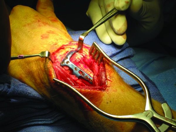
The standard dorsal approach is made to the distal radius. The extensor pollicis longus is released from the third dorsal compartment and the second and fourth dorsal compartments are elevated exposing the fracture site. The Acumed dorsal rim plate is placed on the dorsal aspect under fluoroscopic control. The proximal distal relationship of the plate is assessed under fluoroscopy. Lister's tubercle is frequently involved in the fracture and does not affect the position of the plate. However, in the rare instance where the Lister's tubercle is not involved, it blocks the position of the plate. It can easily be excised so the plate can be positioned properly.
Once the most ideal position of the plate is confirmed, a non-locking screw is placed through the oblong screw hole. In this manner, the plate can be (fine-tuned) adjusted so that the distal rim of the plate supports the dorsal articular surface of the distal radius. It is important to note that the vertical rim of the plate sits parallel to the ulnar aspect of the shaft of the radius.(Fig. 3) As the plate sits along the ulnar aspect of the radial shaft, the first screw placed in the offset hole is aimed in an ulnar to radial direction to get bicortical fixation. If the screw is placed too vertically in the anterior/posterior plane, the screw may only purchase one cortex or be unicortical. The screw is not self-tapping and if the bone is hard, the bone may need to be tapped prior to insertion of the screw.
Fig. 3.
Interoperative radiograph showing the dorsal rim buttress plate stabilizing the comminuted distal radius fracture with dorsal comminution.
Once the ideal location of the plate is confirmed under fluoroscopy, the distal screws may be inserted. Usually, the lunate facet screws are placed first. The plate has three options including non-locking screws, locking screws, or locking pegs. As the screws primarily function as buttress type screws, locking pegs are usually used. However, it is the surgeon's preference and certainly locking or non-locking screws may be used as well. Next, the radial styloid screw is placed in the posterior to anterior direction. The extensor carpi radialis longus and brevis may be retracted radially to gain access to the hole in the plate. However, an easier option is to dissect between the extensor carpi radialis longus and brevis to obtain access to the radial screw hole.(Fig. 4)
Fig. 4.

Interoperative radiograph showing the dissection between the extensor carpi radialis longus and brevis of the forearm to insert the most radial locking screw in the plate.
Following placement of this screw, the homerun screw is placed. This is the screw that runs from an ulnar to radial direction into the very tip of the radial styloid. This screw can be locking or non-locking. If the locking option is used, the locking guide is placed. This guide can be placed initially on the plate prior to inserting the plate onto the bone. It is the author's experience that this sometimes makes the initial plate positioning difficult. It is the author's preference to put the locking guide on after the initial screws have been placed as previously described.(Fig. 5) It is sometimes helpful to place a Hohmann retractor between the radius and ulna. In this manner, the radius can be gently elevated posterior to the ulna to make it easier to place the guide. Once the guide is placed, the homerun screw is inserted into the tip of the radial styloid. Because the homerun screw is relatively long, it is placed just distal to the previously inserted radial styloid screw. This screw then gives some support to the distal aspect of the radial styloid because of its relatively long length. It is important that the screw remains in the cortex and is not placed too long that it projects past the cortex of the radial styloid to irritate the first compartment extensor tendons. The remaining 2.3 mm locking screws are then placed into the radial shaft. Again, these screws may need to be tapped if the bone is hard as the screws are non-tapping screws. (Figs. 6, 7) The extensor pollicis longus is left free and the retinaculum of the second and fourth dorsal compartments are closed.
Fig. 5.

Interoperative radiograph showing the locking drill guide inserted onto the plate for the radial (home run) screw.
Fig. 6.

PA radiograph showing anatomic restoration of the distal radius fracture with the dorsal rim plate.
Fig. 7.

Lateral radiograph demonstrating anatomic restoration of the distal radius fracture with a low profile dorsal rim plate.
Ulnar head fractures are relatively rare, occurring in only ∼6% of all wrist fractures. While fractures of the ulnar head are relatively rare, they can significantly disrupt the congruency and/or stability of the distal radial ulnar joint and limit forearm rotation and hand positioning.
Isolated fractures of the distal ulna usually occur as a result of rotational force applied to the wrist or as a result of a direct blow to the ulnar aspect of the distal forearm such as a night stick fracture. Fractures of the distal portion of the ulna are associated with ligamentous instability and usually occur with fractures of the distal radius. Biyani et al. noted the majority of fractures to the distal ulna are extra articular at its base.6 (Fig. 8) The second most common fracture involves an intra-articular extension and least common are comminuted fractures to the ulnar head. Fractures with significant displacement or those with rotation and malalignment are best treated by open reduction internal fixation to prevent loss of forearm rotation.
Fig. 8.

PA radiograph showing distal fractures of the radius and ulnar head.
There are many options available for stabilization for a distal ulna fracture. These include Kirschner wire fixation, tension band fixation, suture fixation, and plate fixation.7,8,9 However, due to the relatively subcutaneous position of the distal ulna, the majority of these implants are symptomatic and eventually have to be removed. They inhibit forearm rotation and are symptomatic to the patient. There have been relatively very few implants designed specifically to stabilize fractures of the distal ulna.
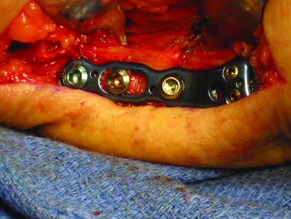
The Acumed (Hillsboro, OR) volar ulnar plate was designed specifically for fractures of the distal ulna head and neck. The implant is usually placed on the volar aspect just proximal to the sigmoid notch to stabilize the ulnar head and not to inhibit forearm rotation. By placing on the volar aspect, it is surrounded by muscle and is less symptomatic requiring fewer potential metal removals.
Surgical Technique
A straight ulnar approach is made between the flexor carpi ulnaris and extensor carpi ulnaris tendons. Blunt dissection is carried down to protect the dorsal sensory branch of the ulnar nerve. The flexor carpi ulnaris and extensor carpi ulnaris are subperiosteally elevated to expose the fracture site. Anatomic reduction of the distal ulnar fracture is performed. Sometimes it is easier to hold the wrist in a straight neutral position to facilitate reduction of the fracture and placement of the plate as compared with full supination of the wrist. Full supination of the wrist makes it easier to place the plate on the volar aspect, but may make reduction of the fracture more difficult.
Once the reduction is performed, the Acumed (Hillsboro, OR) volar ulnar plate is ideally placed on the volar aspect. The plate is placed just proximal to the distal radial ulnar joint so it does not impinge and cause loss of rotation.(Fig. 9) The first screw placed is the 3.5 non-locking screw in the oval slot of the plate. In this manner, the proximal distal relationship of the plate may be fine-tuned under fluoroscopy. Once the plate is secured to the ulnar shaft, a series of locking, non-locking, or locking 2.3 mm pegs may be placed in the distal aspect of the plate. It is important to note that the screws cross as they pass into the ulnar head for increased stability to the fracture site. A single locking guide is inserted into the plate for each of the four distal screws. As the screws are angulated, sometimes it is helpful to take the guide in one of the distal volar plates that are not being inserted to help judge the correct angulation of the guide as it is being screwed into the plate. Which type of screws or pegs is up to the discretion of the surgeon. Usually locking screws or pegs are placed into the distal aspect of the plate as compared with non-locking.(Fig. 10) These screws usually do not have to be tapped as the softer metaphysial bone allows easier insertion for the distal 2.3 mm devices. At the surgeon's discretion, it may be placed straight ulnarly if the fracture pattern is best stabilized by it in this position. If this technique is used, sometimes the opposite sided plate may fit the fracture pattern better. If the plate is placed in the straight ulnar position, it may need to be removed in the future.(Figs. 11, 12)
Fig. 9.
Interoperative radiograph showing volar placement of the volar ulnar plate. The placement of the plate in the volar aspect provides stable fixation with minimal plate irritation.
Fig. 10.

PA radiograph showing anatomic restoration of both the distal radius and ulna fracture. Note the volar ulnar plate is placed just proximal to the sigmoid notch to avoid restriction of forearm rotation.
Fig. 11.

PA radiograph demonstrating plate fixation of both the distal radius and ulna. Due to the obliquity of the fracture line in the AP plane, the plate was placed on the straight ulnar side.
Fig. 12.

Interoperative radiograph showing the volar ulnar plate placed on the straight ulnar side due to the fracture configuration. In this instance, the opposite sided left plate was utilized for the right distal ulnar fracture.
The remaining proximal 3.5 locking screws are placed in the plate. The wound is closed in layers and range of motion is initiated based on the stability of the fixation.
Conflict of Interest The author certifies that he has received payments from a commercial entity relative to this work.
Note
This manuscript does not involve human data and did not require ethical committee approval.
References
- 1.McKay S D, MacDermid J C, Roth J H, Richards R S. Assessment of complications of distal radius fractures and development of a complication checklist. J Hand Surg Am. 2001;26(5):916–922. doi: 10.1053/jhsu.2001.26662. [DOI] [PubMed] [Google Scholar]
- 2.Ring D, Jupiter J B, Brennwald J, Büchler U, Hastings H II. Prospective multicenter trial of a plate for dorsal fixation of distal radius fractures. J Hand Surg Am. 1997;22(5):777–784. doi: 10.1016/S0363-5023(97)80069-X. [DOI] [PubMed] [Google Scholar]
- 3.Ruch D S, Papadonikolakis A. Volar versus dorsal plating in the management of intra-articular distal radius fractures. J Hand Surg Am. 2006;31(1):9–16. doi: 10.1016/j.jhsa.2005.09.011. [DOI] [PubMed] [Google Scholar]
- 4.Simic P M, Robison J, Gardner M J, Gelberman R H, Weiland A J, Boyer M I. Treatment of distal radius fractures with a low-profile dorsal plating system: an outcomes assessment. J Hand Surg Am. 2006;31(3):382–386. doi: 10.1016/j.jhsa.2005.10.016. [DOI] [PubMed] [Google Scholar]
- 5.Kamath A F, Zurakowski D, Day C S. Low-profile dorsal plating for dorsally angulated distal radius fractures: an outcomes study. J Hand Surg Am. 2006;31(7):1061–1067. doi: 10.1016/j.jhsa.2006.05.008. [DOI] [PubMed] [Google Scholar]
- 6.Biyani A, Simison A JM, Klenerman L. Fractures of the distal radius and ulna. J Hand Surg [Br] 1995;20(3):357–364. doi: 10.1016/s0266-7681(05)80094-4. [DOI] [PubMed] [Google Scholar]
- 7.Ring D, McCarty L P, Campbell D, Jupiter J B. Condylar blade plate fixation of unstable fractures of the distal ulna associated with fracture of the distal radius. J Hand Surg Am. 2004;29(1):103–109. doi: 10.1016/j.jhsa.2003.10.019. [DOI] [PubMed] [Google Scholar]
- 8.Grechenig W, Peicha G, Fellinger M. Primary ulnar head prosthesis for the treatment of an irreparable ulnar head fracture dislocation. J Hand Surg [Br] 2001;26(3):269–271. doi: 10.1054/jhsb.2000.0548. [DOI] [PubMed] [Google Scholar]
- 9.Jakab E, Ganos D L, Gagnon S. Isolated intra-articular fracture of the ulnar head. J Orthop Trauma. 1993;7(3):290–292. doi: 10.1097/00005131-199306000-00016. [DOI] [PubMed] [Google Scholar]