Abstract
The field of hadrontherapy has grown rapidly in recent years. At present the therapeutic beam is provided by a cyclotron or a synchrotron, but neither cyclotrons nor synchrotrons present the best performances for hadrontherapy. The new generation of accelerators for hadrontherapy should allow fast active energy modulation and have a high repetition rate, so that moving organs can be appropriately treated in a reasonable time. In addition, a reduction of the dimensions and cost of the accelerators for hadrontherapy would make the acquisition and operation of a hadrontherapy facility more affordable, which would translate into great benefits for the potential hadrontherapy patients. The ‘cyclinac’, an accelerator concept that combines a cyclotron with a high-frequency linear accelerator (linac), is a fast-cycling machine specifically conceived to allow for fast active energy modulation. The present paper focuses on CABOTO (CArbon BOoster for Therapy in Oncology), a compact, efficient high-frequency linac that can accelerate C6+ ions and H2 molecules from 150–410 MeV/u in ∼24 m. The paper presents the latest design of CABOTO and discusses its performances.
Keywords: hadrontherapy, high-gradient linac, cyclinac, carbon ion therapy, multipainting
INTRODUCTION
Current accelerators for hadrontherapy
Nowadays 35 facilities around the world offer proton therapy and just six provide carbon ion therapy [1]. Most of the proton therapy facilities are cyclotron-based centres. Cyclotrons are preferred because of their compactness, reliability and ease of operation and, above everything, the rapid and accurate intensity modulation of their continuous beam. Several companies commercialize cyclotrons for proton therapy. Cyclotrons deliver a fixed energy beam, so absorbers of different thickness are placed along the beam path to get different beam energies in a special section known as the Energy Selection System (ESS), typically about 15 m long. This system allows changing the beam energy in few milliseconds by moving the absorbers in and out of the beam path, but the use of absorbers increases the energy and angular spread of the beam, so a collection of slits and magnets is needed to get a beam with the appropriate performance for the therapy. In addition, absorbers lead to neutron production and machine activation, which demands an appropriate shielding of the line.
Other proton therapy facilities, mainly in Japan, and all the carbon ion facilities are synchrotron-based centres. The main advantage of synchrotrons is their flexibility to accelerate different ions and to vary the performance of their pulsed beam (energy, pulse length), from pulse to pulse, in the machine. The possibility of varying the beam energy in the machine, without absorbers, is especially important for beams of ions heavier than protons, like carbon ions, which fragment into lighter ions and neutrons when traversing the absorbers. The main drawbacks of this kind of machine are that synchrotrons are not as compact as cyclotrons and are not so easy to operate. The typical diameter of a cyclotron for proton therapy is from 4–5 m, whereas a synchrotron has a diameter of 6–9 m. The diameter of a synchrotron for carbon ion therapy goes from 18–25 m, while superconducting cyclotrons for the same purpose would have a diameter of ∼7 m. In addition, synchrotrons require an injection linear accelerator (linac) and a complex extraction system.
Synchrotrons are slow-extraction machines and the organs, which move during irradiation, can be followed using the raster scanning techniques introduced by the Helmhotlz Center for Heavy Ion Research GSI. However this requires, for fast longitudinal feedback, moving absorbers similar to the ones employed in cyclotrons. In HIMAC, the Heavy Ion Medical Accelerator in Chiba, a synchrotron-based hadrontherapy facility, the treatment of moving organs has been possible by inhibiting the beam delivery until the organ is at the planned position, but this system is not optimal because long times are needed to complete the irradiation of the tumour volume [2].
The field of hadrontherapy would benefit greatly from compact, efficient accelerators that would make the setup and operation of a hadrontherapy facility more affordable. The more convenient active energy modulation—preferably fast, i.e. a couple of milliseconds—together with a high repetition rate—of the order of hundreds of hertz—would allow the treatment of moving organs by ‘multipainting’ the target in such a way that each voxel is irradiated ≥ 10 times, while a 3D feedback system would guarantee that the dose was delivered in the proper place, and possible errors corrected during one of the following ‘paintings’ [3].
The cyclinac, the combination of a cyclotron and a high-frequency linac, is an accelerator concept specifically designed for hadrontherapy that has all these characteristics. It was conceived as a fast-cycling machine that would allow varying the beam energy from pulse to pulse by acting on the Radio-Frequency (RF) system of the linac. CABOTO (CArbon BOoster for Therapy in Oncology) is a linac studied in the framework of the European Union funded program PARTNER [4] for tumour treatment with carbon ions. Figure 1 illustrates the cyclinac for hadrontherapy based on CABOTO.
Fig. 1.
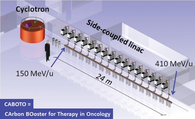
Artist's view of a cyclinac complex for hadrontherapy based on CABOTO.
CABOTO, a high-gradient linac for hadrontherapy
CABOTO is a normal-conducting, high-frequency, fast-cycling linac for hadrontherapy. The present CABOTO design will receive a 12C6+ beam previously accelerated in a cyclotron and will boost its particle energy from 150 up to 410 MeV/u. The carbon ions of 410 MeV/u reach a depth ∼287 mm in water, necessary to treat deep-seated tumours. As discussed above, the high repetition rate—300 Hz in this design—allows the treatment of moving organs with multipainting and 3D feedback.
The linac is divided into different units—each one fed by its own klystron—which in turn is subdivided into different Side-Coupled Cavity (SCC) tanks made of copper, like the one shown in Fig. 2. The SCC scheme was selected for its stability as it operates in the π/2 mode. Each tank has a 5.7 GHz standing-wave RF structure.
Fig. 2.
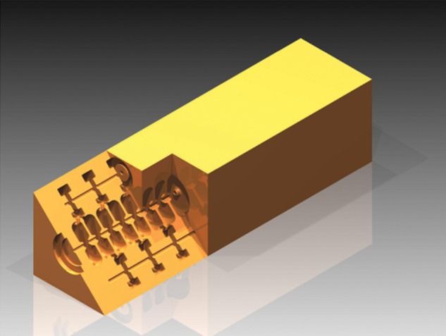
Example of an SCC tank.
Proton therapy cyclinacs were designed to operate at 3 GHz [5], along with many RF linacs like the electron linacs for conventional radiotherapy. The use of higher frequencies may lead to shorter and more efficient machines, and consequently the resonant frequency of CABOTO was chosen to be 5.7 GHz.
The particular RF distribution system of CABOTO allows rapid (1–2 ms), pulse-to-pulse, beam energy modulation by switching off the RF power of a given number of units and varying the power and the phase of the last active unit.
The transverse focusing of the beam is provided by a set of Permanent Magnetic Quadrupoles (PMQs), alternatively placed in the drift spaces between tanks, in a FODO structure that repeats every two tanks. The lattice differs from the traditional FODO structure because: (i) from quadrupole to quadrupole the particles traverse a tank, not a drift tube, so they receive a transversal kick from the RF defocusing forces; (ii) every tank has a different length, therefore the distance between quadrupoles is not constant; and (iii) the quadrupole strengths can be different from tank to tank. Figure 3 shows the RF and focusing scheme of CABOTO.
Fig. 3.
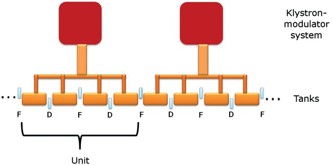
RF and focusing scheme of CABOTO.
MATERIALS AND METHODS
Linac layout design
The design of the linac focused on the optimization of the cell geometry and the structural layout of CABOTO. A previous study had shown that the best output energy of the cyclotron was 150 MeV/u, for machine costs and enhanced medical potentiality reasons [6].
The cell design was optimized to reduce the energy consumption and minimize the probability of an RF breakdown. RF breakdowns cause beam losses, and through losses, material activation, cavity surface damages, radiation and vacuum deterioration, and hence compromise of the reliability of the accelerator. Therefore, the effective shunt impedance (ZTT) (related to the energy consumption) is maximized while keeping the ratios of peak surface electric field Emax over the accelerating gradient E0, and the maximum square root of the modified Poynting vector SC,max1/2 over the accelerating gradient as small as possible. Both the electric field and the modified Poynting vector have been suggested as possible limiting quantities with respect to the high-gradient performance of RF structures. According to the stress model, the stress induced by the electric field on the crystalline structure of the RF cavity surface could cause RF breakdowns [7]. On the other hand, the power flow model proposes the modified Poynting vector as an RF constraint to high-gradient performance of RF structures [8]. The cell geometry optimization was based on RF simulations performed with the code Poisson Superfish [9]. The final cell geometry led to an effective shunt impedance of between 100 and 130 MΩ/m, respectively, for the lowest and the highest-energy cells, and to a ratio (Emax/E0) of ∼4.5 and a ratio (SC,max1/2/E0) of ∼0.024 (MW/mm2)1/2/MV/m.
The code ‘DESIGN’ (personal communication from K Crandall, 2006) was used to define the structural layout of CABOTO: number of units (and consequently klystrons), number of tanks per unit, and number of cells per tank. A compromise between the number of cells per tank and the accelerating gradient excited in the tank had to be found in order to get a reasonably short linac without consuming too much power. In this sense, increasing the number of cells is more efficient, from the energy consumption point of view, than increasing the accelerating gradient for obtaining a given energy gain.
In CABOTO all the cells of a tank had the same length for the sake of simplicity. This choice leads to the well-known problem of synchronicity in the tank, called phase slippage [10]. The phase slippage increases with the number of cells and contributes to the debunching of the accelerated beam, which affects the acceleration efficiency. A larger number of tanks per unit will reduce the effects of phase slippage, but will increase the length of the linac, because of the space required for the quadrupoles of the FODO lattice and the bridge couplers that interconnect the tanks together.
The beam energy modulation in CABOTO depends on the layout of its RF distribution system as well, in particular the number of klystrons and the peak power per klystron, the number of tanks per klystron, and the length of the tanks (which affects the distance between two consecutive quadrupoles of the FODO lattice).
In the final CABOTO design, the linac was divided into 16 units, each unit consisting of four tanks. Each tank had 18 cells per tank. All the quadrupoles of the FODO structure were 60 mm long and had a strength of 200 T/m. The linac could accelerate carbon ions from 150 to 4 MeV/u in 24.1 m. The total installed peak RF power, corresponding to 16 klystrons delivering 12 MW each, was 192 MW. The total RF power used to feed the linac was ∼142 MW, as expected power losses in the RF circuit were ∼25% of the total klystron power. The mean accelerating gradient decreased smoothly from 33.9–32.4 MV/m (from low-energy tanks to high-energy tanks) to keep power below available RF power from klystrons.
Acceleration of cyclotron beam in a high-frequency linac
The beam dynamics in CABOTO were studied with the multiparticle simulation code LINAC (personal communication from K Crandall, 2006) [11]. Space charge effects were not included due to the small beam intensities required for therapy, in the order of nanoamperes.
The present CABOTO design was powered with 2.2 µs-long RF pulses, having a rise time of 0.7 µs and a flat-top length of 1.5 µs, at 300 Hz. Consequently, the duty cycle of CABOTO is about 0.7 × 10⁻¹%. The current required for tumour treatment with carbon ions is ∼0.1 nA (average intensity), so CABOTO had to accelerate about 106 carbon ions per RF pulse. So far no cyclotron delivers carbon ions at 150 MeV/u. Consequently, to study the beam performances of CABOTO, the carbon ion beam delivered by SCENT300 [12], a cyclotron that accelerates carbon ion beams up to 300 MeV/u with normalized emittances (95% of particles) of 2.15 and 4.3 mm mrad in the horizontal and vertical plane, respectively, was rescaled from 300 MeV/u down to 150 MeV/u. The total transmittance of this rescaled beam through CABOTO was ∼2%. The final efficiency of CABOTO, given by the duty cycle times the total transmittance, was ∼10−5. Therefore, CABOTO could provide the sufficient current intensity for hadrontherapy if the beam delivered by the cyclotron, which serves as the injector to CABOTO, had an average current intensity of ∼8 µA.
The layout of CABOTO was specially conceived for actively modulating the energy of the beam. The beam energy can be decreased in steps of about 15–18 MeV/u from the maximum energy of 410 MeV/u by switching off the RF power of a given number of units. The energy step could be reduced down to 2 MeV/u (corresponding to a range step of ∼2 mm in water-equivalent tissue) by varying the field amplitude and the phase of the non-fully active modules. Figure 3 illustrates the beam energy modulation in CABOTO.
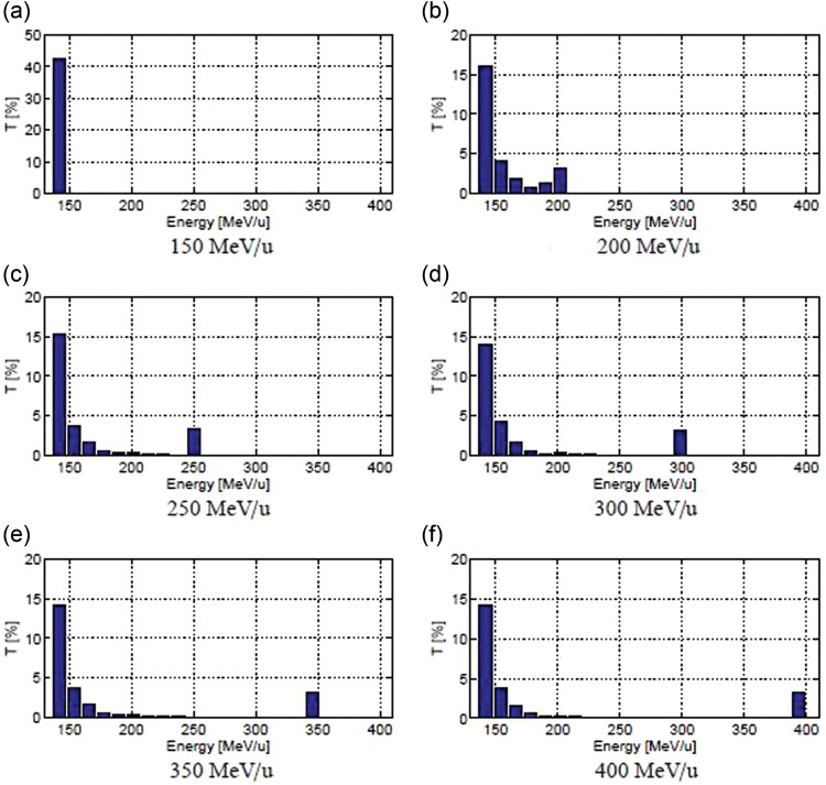
Figure 4 presents the energy distribution for different energy beams. The beam delivered by CABOTO has a tail that contains all the particles remaining outside the acceleration bucket. These particles will be removed from the beam with a bending magnet and a slit located downstream in the linac.
Fig. 4.
Energy distribution of a beam accelerated in CABOTO.
CABOTO could also be used for proton therapy. The linac could accelerate H2 molecules, which would reach 250 MeV/u at about half of the total length of CABOTO. With the RF power of the second half switched off, the output beam would produce 250-MeV protons of variable energy by acting on the RF system. As the minimum proton energy for treatment of deep-seated tumours would be 150 MeV, absorbers of variable thickness could be used to reduce the energy of such a beam.
Evaluation of the expected high-gradient performance
The compactness of the cyclinacs relies on the use of high-gradient technology. However, the high-gradient performance of RF structures is limited by the occurrence of RF breakdowns. In the framework of the studies of high-gradient linacs for hadrontherapy, a high-gradient test program was initiated to explore the high-gradient limitations of RF structures operating between 3 and 5.7 GHz, and to understand which frequency could be the most appropriate for design of the medical accelerators. The high-gradient test program envisaged the design, prototyping and high RF power testing of several RF structures operating in that frequency range, in particular, (i) one 3 GHz single-cell cavity, (ii) three 5.7 GHz single-cell cavities, and (iii) a multi-cell structure with resonant frequency, to be chosen with the experience acquired from the preparation and testing of the previous test devices.
The high-power tests of a 3-GHz single-cell cavity performed in the CLIC Test Facility (CTF3) at CERN (Switzerland) were completed in March 2012. It is of note that during high-power operation of the test cavity with 2.2 µs-long (flat-top) RF pulses and for a maximum modified Poynting vector of about 0.87 MW/mm2, a Break Down Rate (BDR) smaller than 3.6 × 10⁻⁶ breakdowns per pulse per metre (bpp/m) was measured, because no breakdown events were detected in ∼81 h for operation at 50 Hz. (The length of the cavity was 0.0189 m) [13].
The expected high-gradient performance of CABOTO was evaluated from experimental data collected during the test. The estimation was done assuming that the modified Poynting vector SC is the electromagnetic quantity that limits high-gradient performance. In addition, the hypothesis that the same BDR can be obtained at 5.7 GHz was made. However, this assumption is conservative since it is known that the limit improves when the frequency is increased.
The maximum accelerating gradient in a CABOTO cell is 39 MV/m when the maximum Poynting vector is 0.87 MW/mm2—the same value as for the measurement of the test cavity. With the previous assumptions, this means that the expected BDR for a CABOTO cell receiving 2.2 µs-long (flat-top) RF pulses and being operated at 39 MV/m accelerating gradient is 3.6 × 10⁻⁶ bpp/m—a given modified Poynting vector value is related to a certain BDR. During the high RF power tests, the BDR was measured for different electric field and pulse length values. A power dependence of the BDR on the electric field (E) of about 10 (i.e. BDR ≃ E10) was found for measurements performed in the range of SC from 1.88–2.86 MW/mm2. The BDR scaled to the pulse length τ to the third power (i.e. BDR; τ3). According to the above-mentioned experimental results and the scaling laws, CABOTO, designed for 1.5 µs-long (flat-top) RF pulses and 34 MV/m accelerating gradient at maximum, would present a BDR of around 3 × 10⁻⁷ bpp.
This is an acceptable value of BDR because it corresponds to one breakdown every 8 min when operating the 24-m CABOTO linac at 300 Hz. This BDR will be easily corrected with the multipainting technique.
In 2013 the 5.7 GHz single-cell cavities will be high-power tested with the modulator and magnetron system lent by ADAM SA (Switzerland). The tests should show which frequency, 3 GHz or 5.7 GHz, is more suitable in terms of high-gradient performance, machining and manipulation requirements.
RESULTS AND DISCUSSION
The design of a compact, efficient fast-cycling linac, CABOTO, was presented. Table 1 summarizes the main characteristics of CABOTO. The division of the linac into independently fed units allows varying of the beam energy from pulse to pulse, in 1–2 ms, by acting on the RF system, so no absorbers are needed to fast scan the tumour in depth. The beam energy can be changed in small steps to provide a minimum range step of 2 mm in water. The modularity of CABOTO has the added value of facilitating maintenance, reparation, upgrading and extension of the facility.
Table 1.
Main characteristics of CABOTO
| CABOTO | ||
|---|---|---|
| Particle | C6+, H2 | |
| Input energy | MeV/u | 150 |
| Output energy | MeV/u | 410 |
| Energy step by switching off a linac unit | MeV/u | 15–18 |
| Number of units (= number of klystrons) | 16 | |
| Total linac length | M | 24.1 |
| Resonant frequency | GHz | 5.7 |
| Accelerating gradient | MV/m | 32–34 |
| Max. surface electric field | MV/m | 153 |
| Max. mod. Poynting vector | MW/mm2 | 0.61 |
| Synchronous phase | Degrees | –14 |
| Beam hole diameter | mm | 5 |
| Effective shunt impedance | MOhm/m | 100–130 |
| Energy Consumption | ||
| Duration of high-voltage RF pulses | μs | 2.2 |
| Duty cycle | % | 0.066 |
| Peak power per unit (with 25% losses) | MW | 12 (9) |
| Total peak RF power (available with 25% losses) | MW | 192 (144) |
| Wall plug power for the linac | kW | 400 |
| Transverse Focusing System | ||
| Number of Permanent Magnetic Quadrupoles (PMQs) | 65 | |
| Gradient of the PMQs | T/m | 200 |
| Length of the PMQs | mm | 60 |
| Beam Performances | ||
| Duration of RF flat-top | μs | 1.5 |
| Repetition rate | Hz | 300 |
| Normalized transverse acceptance at linac entrance | mm mrd | 2.79 |
| Transmittance | % | 2 |
The performances of CABOTO, in particular the fast active energy modulation and the high repetition rate of the linac (300 Hz), allow the spot scanning technique with multipainting. In combination with a 3D feedback system, the beam of CABOTO could be used to treat moving organs. CABOTO is designed for carbon ion therapy, but can also be used for proton therapy.
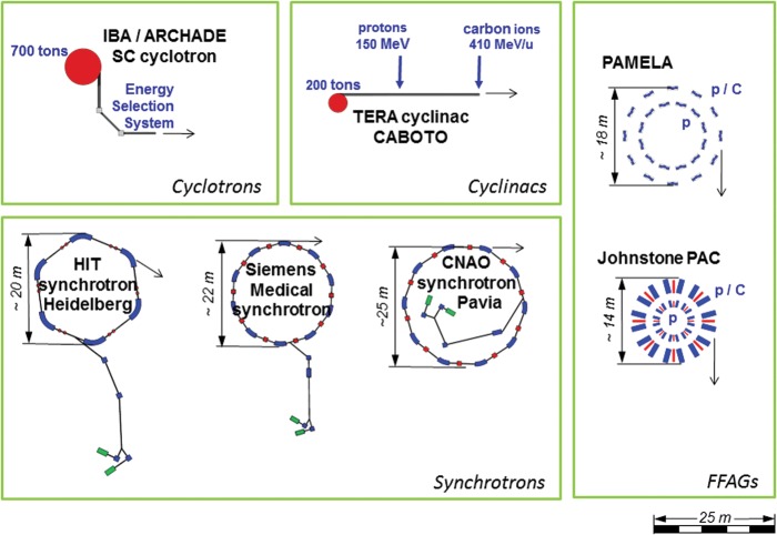
CABOTO is about 24 m long, comparable to the diameter of the synchrotrons in operation for hadrontherapy. Figure 5 [14] shows a dimensional comparison of different accelerator complexes for hadrontherapy, including the Fixed-Field Accelerating Gradient (FFAG) accelerators. The compactness of CABOTO was possible thanks to high-gradient technology. The high-gradient performance of CABOTO was estimated from experimental data of the high RF power test of a 3-GHz single-cell cavity, with the estimated BDR within the clinical requirements. The high-gradient test program will continue with the high RF power testing of the 5.7-GHz single-cell cavities. These tests should give insight about the most suited frequency for RF structures for medical applications.
Fig. 5.
Dimensional comparison of different accelerator solutions for hadrontherapy [14].
It has to be underlined that a non-negligible part of the operation cost of a carbon therapy synchrotron is the electricity bill. The total plug power required to run CABOTO is ∼400 kW. [The average power 12 × 16 × 0.7 × 10−3 = 150 kW, but to produce the RF power one has to divide this by the efficiency of the klystron (0.45) and take into account the low power consumptions. We usually multiply by an overall factor equal to 3.]
Some issues do need further studies, in particular the transport magnetic line and the slit(s) required to select the particles with the desired energy from the output beam of CABOTO. Another issue is the effect of the RF jitter on the beam performances. Particle losses due to the particular beam dynamics of CABOTO may lead to radiation-induced demagnetization of the permanent quadrupoles of the FODO lattice, and may cause some machine activation. A high RF power test of a CABOTO tank would not only provide understanding of the exposure time for the PMQs but also the shielding required for the linac.
Despite the promising features of the active energy modulation system of CABOTO, it has some drawbacks. In particular, it needs a large number of costly 5.7 GHz modulator/klystron systems, which increases the capital cost of the facility with respect to 3-GHz proton cyclinacs. Fortunately, the interest in this resonant frequency is rising, and many facilities and research groups are nowadays considering or already using high RF power devices at 5.7 GHz, which in the next years will increase the availability of RF power sources and control systems operating at this frequency.
The future accelerators for hadrontherapy should allow the best possible treatment modality with lower investment and running costs than the present facilities. Cyclinacs show cost and space advantages when compared with synchrotron-based solutions for carbon ion therapy, as well as an improved performance in scanning speed, permitting rapid scanning and frequent repainting. Their beam is especially suited for the spot scanning technique with multipainting, the best way to treat moving organs.
FUNDING
This work was supported by the Seventh Framework Programme (FP7/2007–2013-215840-2).
ACKNOWLEDGEMENTS
Thanks to A. Degiovanni and P. Posocco for discussion on this work.
REFERENCES
- 1.Particle Therapy Co-Operative Group (PTCOG) Centers in Operation. http://ptcog.web.psi.ch/ (12 December 2012, date last accessed) [Google Scholar]
- 2.Kitagawa A, Fujita T, Fukumura A, et al. Status of a carbon-ion therapy facility and development for advanced treatment. J Korean Phys Soc. 2008;53:3709–13. [Google Scholar]
- 3.Amaldi U, Bonomi R, Braccini S, et al. Accelerators for hadrontherapy: from Lawrence cyclotrons to linacs. Nucl Instr Meth Phys Res. 2010;620:563–77. [Google Scholar]
- 4.PARticle Training Network for European Radiotherapy (PARTNER) doi: 10.1093/jrr/rrt013. http://enlight.web.cern.ch/project/partner. (12 December 2012, date last accessed) [DOI] [PMC free article] [PubMed] [Google Scholar]
- 5.Amaldi U, Berra P, Crandall K, et al. LIBO – A LInac BOoster for protontherapy: construction and tests of a prototype. Nucl Instr Meth Phys Res. 2010;521:512–29. [Google Scholar]
- 6.Garonna A. Ph.D. Thesis. Switzerland: École Polytechnique Fédérale de Lausanne; 2011. Cyclotron designs for ion beam therapy with cyclinacs. [Google Scholar]
- 7.Nordlund K, Djurabekova F. Defect model for the dependence of breakdown rate on external electric fields. Physical Review Special Topics – Accelerators and Beams. 2012;15 [Google Scholar]
- 8.Grudiev A, Calatroni S, Wuensch W. A new local field quantity describing the high gradient limit of accelerating structures. Phys Rev ST Accel Beams. 2009;12:102001. [Google Scholar]
- 9.Poisson Superfish. http://laacg1.lanl.gov/laacg/ (12 December 2012, date last accessed) [Google Scholar]
- 10.Wangler TP. Principles of RF Linear Accelerators. 2nd edn. Darmstadt: John Wiley & Sons Inc; 2008. pp. 189–190. [Google Scholar]
- 11.Nath S, Ryne RD, Stovall J, et al. Comparison of Linac Simulation Codes. Lawrence Berkeley National Laboratory; 2001. [Google Scholar]
- 12.Maggiore M, Calabretta L, Camarda M, et al. Design Study of Medical Cyclotron SCENT300. Proceedings of the Heavy Ion Accelerator Technology – HIAT 2009, Venice, Italy [Google Scholar]
- 13.Verdú-Andrés S. Spain: University of Valencia; 2012. High-gradient accelerating structure studies and their application in hadrontherapy. Ph.D. Thesis. [Google Scholar]
- 14.Verdú-Andrés S. Comparison between RF linacs and FFAGs for hadrontherapy, 3rd deliverable of Work Package 25 for the PARTNER collaboration (Switzerland, 2011). [Google Scholar]


