

Abstract
For many years, high-speed countercurrent chromatography conducted in open tubing coils has been widely used for the separation of natural and synthetic compounds. In this method, the retention of the stationary phase is solely provided by the Archimedean screw effect by rotating the coiled column in the centrifugal force field. However, the system fails to retain enough of the stationary phase for polar solvent systems such as the aqueous–aqueous polymer phase systems. To address this problem, the geometry of the coiled channel was modified to a spiral configuration so that the system could utilize the radially acting centrifugal force. This successfully improved the retention of the stationary phase. Two different types of spiral columns were fabricated: the spiral disk assembly, made by stacking multiple plastic disks with single or four interwoven spiral channels connected in series, and the spiral tube assembly, made by inserting the tetrafluoroethylene tubing into a spiral frame (spiral tube support). The capabilities of these column assemblies were successfully demonstrated by separations of peptides and proteins with polar two-phase solvent systems whose stationary phases had not been well retained in the earlier multilayer coil separation column for high-speed countercurrent chromatography.
Introduction
Countercurrent chromatography (CCC) is a unique partition chromatography method with a liquid stationary phase that avoids the sample loss and denaturation that occurs on solid supports of column chromatography (1–8). The method was performed in a planetary centrifuge, which held tubing coiled in helices and was centrifuged at 500 rpm, as introduced in 1973 (4). The stationary phase is very high in volume; thus, higher sample loads are normal. High-speed CCC (HSCCC), introduced in the 1980s, improved the partition efficiency and separation time by using a compact multilayer coil separation column coaxially mounted on the rotary frame of the type-J coil planet centrifuge, which was operated at 1,000 to 1,200 rpm (8–10). In the centrifuge, the coiled separation column revolves around the central axis of the centrifuge while it synchronously rotates about its own axis. This planetary motion has two major functions: the mobile phase can be passed through the centrifuge rotor without rotary seals, and a large amount of stationary phase is retained while the two phases are mixed along the length of the column to produce a highly efficient solute separation. Since its introduction, HSCCC has been widely used for the separation and purification of natural products and synthetic compounds (11–13). One problem associated with the HSCCC technique using a multilayer coil is that there is less retention of the stationary phase for polar and more viscous solvent systems. Because a high retention of the stationary phase is essential for efficient preparative-scale separations, two designs of separation columns have been introduced. One is called the spiral disk assembly (14–16) and the other is the spiral tube support assembly (17–18), both of which have improved stationary phase retention without loss of partition efficiency. Consequently, new spiral HSCCC conducted in the same type-J planet centrifuge has been successfully applied to the separation of polar compounds such as proteins using aqueous–aqueous polymer phase systems. This review details the development of spiral HSCCC, focusing on column design, stationary phase retention and partition efficiency, together with typical applications in the separation of polar compounds using polar solvent systems. Although spiral CCC with a focus on proteins was reviewed a few years ago (19), this review highlights the structural features that evolved and were instrumental in the development of the spiral design columns and their resulting new applications.
In CCC, the separation unit identified as the column was basically open tubing coaxially coiled in layers on a spool, whereas in spiral CCC, the tubing is spread out in spirals. The spiral column is centrifuged similarly in a coil planet centrifuge with the continuous inflow and outflow tubing able to twist and untwist in the motion. The separation unit is also a rotor, which is what it is sometimes called for brevity. The spiral separation columns can be mounted either singly or with two counterbalancing in commercially available planet centrifuges.
The spiral configuration for HSCCC is made in two different ways: one comprises spiral grooves made in an inert plastic plate, the spiral disk (14); the other is a frame of circular channels, the spiral tubing support (STS), in which flow tubing is held in layers (17). Each design has its own special features that are adaptable: the spiral disk has an advantage in that the spiral channel can be modified to contain glass beads that mix the phases under fluctuating centrifugal force fields (20–21). In the STS rotor, it is possible to change the shape of the flow tubing with perpendicular presses on the walls (18), for example, or flattening and twisting on its axis (22). These modifications have been shown to improve the performance.
Development of Spiral Disk Columns
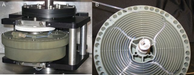
The first spiral configuration that was made and found to be useful for chromatography is shown in Figure 1A and the first adaptation to four interwoven spirals is shown in Figure 1B (14). These spiral disks are the origin of spiral HSCCC and the resulting research described here. The spiral disks were made of 16 cm diameter and 5 mm thick plates of polymonochlorotrifluoroethylene (Kel-F), in which spiral grooves were formed in various dimensions. All tested spirals are Archimedean spirals, which have an equidistant pitch throughout the plate and the spiral pathway is formed clockwise from the center out. This is important for the elution mode designation, to be described later. Under the disk is a small diameter radial return channel to carry the flow to the center of the disk below or to the beginning of the subsequent spiral on the same disk. This is shown in the cross section drawing in Figure 1. The spiral and underneath flow channels are sealed with a polytetrafluoroethylene (PTFE) or Teflon (polytetrafluoroethylene) sheet or septum and all are sandwiched between a pair of metal end plates, which are bolted to provide a tight seal. The individual components used in the assembly of the spiral disk rotor, the Kel-F plate, septum and end flanges have been pictured previously (14), and Figure 2 shows the assembled rotors. Studies with various spiral channel designs in one plate were conducted by using the assembly shown in Figure 2A. In Figure 2B is an assembled rotor of eight stacked single-spiral disks. Another multiple disk rotor has been made with modified disks described in the following. However, a series of studies were undertaken regarding the dimensions of the spirals, varying the depth, pitch and width and incorporating interwoven spirals on a disk to discover the best design of the spiral channel.
Figure 1.

Design drawings of spiral disks with cross sections that show return channels with inner (I) and outer (O) entries: spiral disk with single spiral channel (A); spiral disk with four spiral channels (B).
Figure 2.

Photos of the spiral disk assembly of one disk (A); an assembled rotor of eight disks (B).
Studies of initial spiral designs
Four designs of spiral channels were examined in single disks assembled as shown in Figure 2A and tested for their functionality. Two of the disks had a single spiral with different dimensions (depth and width) and the others had four interwoven spirals with the same varying dimensions but with varying pitch, as shown in Figure 3. The interwoven spiral channels were connected serially via return channels on the underside of the PTFE plate (Figure 1B). The total volume capacity of each spiral in an assembled rotor was similar: 21–23 mL.
Figure 3.

Retention of stationary phase in four different spiral disk designs. Column I is a single spiral in a disk (Figure 1A) with a channel 2.0 mm deep and 2.6 mm wide and a pitch of 4 mm (distance between channels); Column II is a single spiral 3.7 mm deep and 1.5 mm wide with 4 mm pitch, Column III is a disk of four interwoven spirals, as shown in Figure 1B, with the same dimensions of Column I, but with a distance of 16 mm between channels (16 mm pitch); Column IV is a four-spiral disk with the same dimensions of Column II except for a pitch of 16 mm. The sample types with their solvent systems are indicated and further details are in the text.
Each spiral disk was tested with respect to the retention of the stationary phase and the calculation of partition efficiency by using three different kinds of two-phase solvent systems with suitable test samples. Test samples of di-peptides, Trp-Tyr (0.5 mg) and Val-Tyr (2 mg), were chromatographed with a solvent system of n-butanol–acetic acid–water (BAW) (4:1:5 by volume). A lysozyme and myoglobin protein mix (10 mg each) was separated in the aqueous two-phase solvent system (ATPS) of polyethylene glycol (PEG) and PEG-dextran; all experiments were conducted at a revolutional speed of 800 rpm. The plots of the results are presented in Figure 3 as the stationary phase retentions of the spiral disks at different flow rates (19). The four lines in each diagram indicate the percentage of stationary phase retention obtained at different elution modes, as indicated below the diagram. The elution modes are shown in Figure 4. As shown in Figure 4, “L-I-T” indicates that the lower phase is pumped into the inner entry of the spiral in the tail to head direction with counterclockwise rotation and “U-O-H” means that the upper phase is pumped in from the outer entry (bottom) in counterclockwise revolution. In the BAW solvent system, the single-spiral disks (Columns I and II) showed great variation in retention levels at the elution modes, in which U-O-H and L-I-H produced the highest retention levels, whereas in Columns III and IV, the four-spiral disks, all elution modes similarly yielded excellent retention levels of over 50% up to the maximum flow rate of 5 mL/min. In the polymer phase system of PEG–K2HPO4, Column I produced a higher retention level than Column II, in which the retention level was sharply decreased as the flow rate was increased, whereas the four-spiral disks maintained high retention levels. In the more viscous dextran-PEG polymer phase system (Figure 3), the retention levels were markedly decreased in all spiral disks, but the four-spiral disks produced sufficient retention levels of over 50% at a low flow rate of 0.5 mL/min in all elution modes. The overall results of the experiments indicated that the four-spiral disks (Columns III and IV) produced satisfactory levels of stationary phase retention in all tested two-phase solvent systems.
Figure 4.

Head and tail orientation of the spiral (disk and STS rotors), which are clockwise from the center out and change with the direction of rotation (28). The top of the spiral is the inner terminal and winds clockwise to the other end at the bottom, outer or peripheral terminal. The flow of either mobile phase [upper phase (U) or lower phase (L)] can be into the top (inner) or in from the bottom (outer). Thus, the inner terminal is the head in the clockwise rotation and conversely, the outer terminal is the head in counterclockwise. For example, “L-I-T” indicates that the lower phase is pumped into the inner entry of the spiral in the tail to head direction with counterclockwise rotation. “U-O-H” means that the upper phase is pumped in from the outer entry (bottom) in counterclockwise revolution.
The partition efficiency levels of the test compounds in the spiral disks were calculated for all flow rates and elution modes (14). The results are not shown, but in the BAW solvent system, the best di-peptide separations were obtained in the L-I-T and U-O-H elution modes in both the single- and four-spiral disks, with the single-spiral disks producing a higher peak resolution at up to 2 mL/min. However, the protein separations were quite disappointing. Despite a sufficient level of stationary phase retention, only a small degree of separation occurred in Column II (U-O-H) at a low flow rate of 0.5 mL/min. In the separation of small molecules in the multilayer coil, a satisfactory peak resolution was always attained from a high level of stationary phase retention (with the organic–aqueous solvent systems). The separation of the proteins was not successful in these spiral disks, despite a satisfactory level of stationary phase retention. These results clearly indicated that protein molecules with high molecular weight require a longer mass transfer time through the interface between the two phases. One of the strategies to improve the partition efficiency of proteins is to increase the interfacial area by interrupting the laminar flow of the two phases through the spiral channel. For this purpose, the shape of the spiral flow channel was modified in various ways.
Modified spiral channel designs
First, short segments of Teflon tubing were inserted into the spiral channel at regular intervals to disturb the laminar flow at the walls of the two phases (15). The peak resolutions of proteins were substantially improved as the number of inserts was increased. With this encouraging finding, a bead-chain spiral disk was fabricated that had over 1,000 small, round partition holes connected with short, narrow ducts, as shown in Figure 5A (16). As expected, this improved the partition efficiency of the protein samples. However, when the partition efficiency was calculated, it was found that 40 bead-chain units are required to yield one theoretical plate. This indicated that something significant was needed to improve the partition efficiency. Two different designs of the spiral disk were developed to accommodate a glass bead in every other compartment to actively mix the two phases for enhanced mass transfer (17, 18). One was a locular spiral channel that consisted of approximately 700 short rectangular sections/disks called “locules” that were connected in series with narrow ducts, as shown in Figure 5B. The other type (Figure 5C) was a barricaded spiral disk in which the channel was divided into over 700 sections by placing barricades at regular intervals. These barricades were placed at the center of the channel so that two solvent phases could freely flow by the sides of each barricade.
Figure 5.

Modified channel configurations of the spiral disk. Portions of photos of the disks: bead-chain spiral disk (A); locular spiral disk (B); barricaded spiral disk (C).
The partition efficiency levels produced by four different spiral channels were compared, and the locular disk with no glass bead improved peak resolution with partial resolution of proteins in all elution modes over the original four-spiral disk. Much better separations were attained from both bead-containing systems. The barricaded disk (labeled as a mixer-settler) showed a slightly higher retention of the stationary phase than the beaded locular disk. Based on these results, the barricaded design was incorporated into the mixer-settler spiral disk, named after the mixing and settling sections. The mixing improved the partition efficiency and the settling section improved the stationary phase retention.
Mixer-settler spiral countercurrent chromatography
An assembly of eight four-spiral disks (as shown in Figure 2B) with barricaded channels and glass beads in every other space was fabricated and used for studies of protein separation (21). A photo of the detail in a mixer-settler disk fabricated by injection molding is shown in Figure 6. The mixer-settler spiral CCC is under commercial development (CC Biotech LLC, Rockville, MD). Figure 7A shows the separation of five proteins in the mixer-settler CCC under HSCCC conditions. Four proteins were eluted in nice sharp peaks at partition efficiency levels of several hundred theoretical plates while the last protein was retained in the column. This chromatogram may represent the best protein separation thus far achieved by CCC. A separation of another set of five proteins of higher molecular weight (MW), including glycoproteins, is shown in Figure 7B, in which all five proteins were well resolved (19, 21). The question of whether vibrating glass beads might denature the proteins is answered by the recovery of highly active enzyme fractions from the purification of myosinase from an extract of kaiware daikon sprouts (J. Fahey and Y. Ito, unpublished results). In early, limited studies of using this rotor with the BAW solvent system, satisfactory retention of the stationary phase did not seem to happen, and results with small molecules were not satisfactory. Thus, the mixer-settler has a specifically high suitability for the ATPS, and hence, for protein separation.
Figure 6.

Photo of mixer-settler spiral disk detail. The barricaded disk is made of injection molded polyethylene containing glass beads (CC Biotech).
Figure 7.

Protein separations by mixer-settler CCC with an eight-plate barricaded spiral disk assembly with 160 mL capacity: separation of a protein mix of 5–6 mg each of cytochrome c, myoglobin, ovalbumin, lysozyme and bovine serum albumin (which was retained in the column) at 800 rpm and 0.25 mL/min with 280 nm detection, in which the retention of the stationary phase was 52% in the solvent system of 12.5% (w/w) PEG-1000 and 12.5% (w/w) K2HPO4 with the lower mobile phase (A); separation of a mix of five proteins, 5 mg of cytochrome c and 20 mg each of human serum albumin, β-lactoglobulin, α-chymotrypsin and trypsinogen in the solvent system consisting of PEG1000-K2HPO4–KH2PO4–H2O (16:8.3:4.2:71.5, w/w); flow rate: 0.5 mL/min; rpm: 1,000; stationary phase retention: 53.6% (B).
The understanding of the mechanism of the mixer-settler spiral disk is derived from studies of the locular spiral disk with glass beads. Fluctuation of the centrifugal force field, generated by the planetary motion, produces vigorous agitation of the two phases by vibration of the glass bead in the mixing locule and the two phases are settled in the next empty locule by the centrifugal force. The mobile phase entering the mixing locule is mixed with the stationary phase and a mixture of the two phases enters the next empty locule for settling. Therefore, the system tends to gradually lose the stationary phase from the mixing locule. This problem is solved by the barricaded spiral disk with open spaces around the barricade wall. The two phases can freely undergo countercurrent partitioning through the opening at the top and bottom (relative to the rotor axis) of each barricade; hence, the system can maintain a stable retention of the stationary phase (the mechanism is diagrammed in Supplementary Figure 1) (19).
Performance of the multiple-layer single-spiral disk rotor
With the single-spiral eight-disk separation column or rotor, a series of experiments was conducted to assess the use of various types of solvent systems and the utility for the preparative purification of peptides. At the HSCCC flow rate of 2 mL/min in the multilayer coil, the stationary phase is highly retained at 80% or more of the high interfacial tension two-phase solvent systems. Because of the large density difference between the phases, as with hexane–water, rapid separation of the phases occurs after these (relatively nonpolar) solvent systems are mixed. Small molecules and natural products are readily separated with these organic–aqueous solvent systems. However, it was found that with the heavy alcohol–aqueous (polar) two-phase solvent systems, low stationary phase retention occurs in the multilayer coil, which makes it difficult to operate in HSCCC conditions. The polar solvent systems, such as BAW or sec-butanol–water, which are useful for peptides, proteins and other high MW entities, were not satisfactorily retained in the multilayer coil in the type J planetary centrifuges. In some cases, only the upper phase had enough stationary phase retention (approximately 40%), so that a compound had to have a suitable partition coefficient to be used with the lower mobile phase. In spiral CCC, the stationary phase is much higher at the rpm rates used in HSCCC; thus, high resolution and the separation of impurities are possible in the preparative chromatography of compounds that are soluble in the polar solvent systems.
Solvent system studies
The potential for this was identified years ago in studies of the retention of polar and nonpolar solvent systems in a model single spiral disk in the type-J planetary centrifuge (5, 23–24) and reevaluated more recently by others (25). The retention of the stationary phase is dependent upon the spiral screw direction, which determines the direction of solvent flow, and upon the planetary force induced by the centrifugal rate. Higher stationary phase retentions were identified for some hydrophilic polar solvents in certain flow directions. In a spiral separation rotor that is comprised of a stack of plates, all in the same screw direction (compared to alternating screw directions for wrapped multilayer tubing coils), the same effects are expected to be found. Therefore, the retention of polar solvent systems was measured to determine the actual values and whether they are high enough for suitable functions.
The retention of the stationary phase was determined by filling the rotor with the stationary phase, starting the centrifugation at 800 rpm and eluting the mobile phase at 2 mL/min. After the breakthrough of the mobile phase, the centrifugation and flow are stopped and the contents are expelled with helium pressure into a graduated cylinder. The retained volume of stationary phase is measured as a percentage of the total volume. This was determined for all elution conditions. The stationary phase retention values expressed, as the percent of the total volume capacity, are listed in Table I and continue in Table II in decreasing order of the upper stationary phase retained in the elution mode of the lower mobile phase (L-I-T) (26). Organized in this way, the solvent systems seem to follow the order of decreasing polarity or increasing hydrophobicity. Table I contains the polar solvents and Table II includes the nonpolar or less polar solvents, which are the solvent systems with high density differences. Significantly, for all solvent systems, there is over 50% retention of the stationary phase for all mobile phases at 2 mL/min in either a head to tail or a tail to head flow direction. Thus, larger molecules that have useful partition coefficients in these solvent systems can be separated with either mobile phase. The first four solvent systems in Table I produced high retention of the stationary phases, ranging from 78.9 to 58.4% for the upper phase in the L-I-T condition; in this condition for the last four solvent systems in Table II, this is the lowest retained condition, from 15.8 to 0%. In the condition of upper phase as the mobile phase U-O-T, the highest percentage of stationary phase was attained in the nonpolar or hydrophobic solvent systems at the bottom of Table II. The retention values ranged from 68.6 to 91.3%. As the solvent system became more polar or hydrophilic, the higher stationary phase retention for the upper mobile phase became higher for the head to tail elution mode (54.5 to 78.4%).
Table I.
Highly Polar Solvent Systems: SF
| Solvent system (by volume) | Elution mode | Stationary phase (%) |
|---|---|---|
| n-Butanol–acetic acid–water (4:1:5) | L-I-T | 78.9 |
| L-I-H | 39.9 | |
| U-O-H | 78.4 | |
| U-O-T | 22.8 | |
| sec-Butanol–water (1:1) | L-I-T | 76.6 |
| L-I-H | 46.5 | |
| U-O-H | 66.7 | |
| U-O-T | 63.6 | |
| sec-Butanol–1% aqueous TFA (1:1) | L-I-T | 70.3 |
| L-I-H | 54.1 | |
| U-O-H | 66.4 | |
| U-O-T | 73.3 | |
| n-Butanol–sec-butanol–1% aqueous TFA (1:1:2) | L-I-T | 58.4 |
| L-I-H | 53.2 | |
| U-O-H | 54.5 | |
| U-O-T | 49.4 | |
| n-Butanol–1% aqueous TFA (1:1) | L-I-T | 10.0 |
| L-I-H | 57.5 | |
| U-O-H | 42.3 | |
| U-O-T | 51.6 |
Table II.
Nonpolar (Organic–Aqueous) Solvent Systems: SF
| Solvent system | Elution mode | Stationary phase (%) |
|---|---|---|
| n-Butanol–water (1:1) | L-I-T | 1.6 |
| L-I-H | 67.6 | |
| U-O-H | 27.5 | |
| U-O-T | 68.6 | |
| t-Butyl methyl ether–n-butanol–acetonitrile–0.1% aqueous TFA (2:2:1:5) | L-I-T | 0 |
| L-I-H | 74.3 | |
| U-O-H | 20.3 | |
| U-O-T | 53.7 | |
| t-Butyl methyl ether–acetonitrile–1% aqueous TFA (2:2:3) | L-I-T | 0 |
| L-I-H | 75.2 | |
| U-O-H | 15.8 | |
| U-O-T | 85.7 | |
| n-Hexane–ethyl acetate–methanol–water (3:5:3:5) | L-I-T | 0 |
| L-I-H | 81.1 | |
| U-O-H | 11.3 | |
| U-O-T | 91.3 |
In the multilayer coil, the hydrophobic solvent systems displayed a unilateral hydrodynamic distribution of the upper phase to the head end and lower phase to the tail end at a critical high flow and centrifugal rate (5, 23). The intermediate and polar solvent systems had a more complex distribution in the multilayer coil; generally, the phases went in the opposite direction with less retention of the stationary phase. The strong centrifugal force field holding the hydrophobic solvent systems had less effect on the hydrophilic solvents. The viscosity of the phases had some effect on the retention of the stationary phase, but the physical property that correlates with the low stationary phase retention of these solvent systems is the separation time of the phases (24). The solvent systems that equilibrated slower than 30 s did not distribute strongly to the head and tail, as do the hydrophobic solvent systems. The solvent systems with much faster separation times, indicative of high interfacial tension, did display this unilateral distribution. These results are in accordance with previous model studies of single-layer spirals that differentiated the behavior of solvent systems (5, 23, 24). Now, a unidirectional spiral flow path has been applied in a manifold to provide a larger volume capacity. The important advantage of the spiral rotor is that there is high retention of the stationary phase for all solvent systems in a particular elution mode for each mobile phase. These tables show a useful listing of the operating conditions for the polar to nonpolar solvent systems in spiral CCC.
Single-spiral disk rotor applications
The single-spiral eight-disk rotor was used for preparative separations of hydrophobic peptides that were not well recovered by semipreparative purification on reversed-phase columns. The applications to three peptides have been published. The hydrophobic sequence of the GP120 coat protein of the HIV virus was the first peptide, aside from model di-peptides, which were chromatographed in the spiral disk rotor. The crude synthetic product was purified to over 95% purity, as determined by analytical high-performance liquid chromatography (HPLC), and a good yield was recovered (27). The sequence of the peptide is WANLWNWFIDSNWLW and it is not water soluble at normal pH. A volatile solvent system that is suitable for acid-sensitive compounds was modified for this peptide. The solvent system was n-butanol–pyridine–acetic acid–water in the volume ratios of 8:2:1:9. The solvent system can be modified by substituting sec-butanol to modify the partition coefficient (K) for other peptides, if necessary. Another peptide with a hydrophobic sequence, SAGSADQYLAVPQAPYQWA, is shown in Figure 8 (26) and Table III. In the 153 mL volume rotor, a 62 mg sample load was able to be chromatographed and pure peptide was recovered from the center of the eluted peak. These experiments showed a high mass loading capacity for the preparative purification of synthetic peptides.
Figure 8.

Hydrophobic peptide SAGSADQYLAVPQAPYQWA. An amount of 62 mg was loaded in sec-butanol–0.1% aqueous TFA with the lower mobile phase at 1 mL/min and 800 rpm. The chromatogram is a plot of the absorbance at 280 nm of the fractions (A). The analysis of fractions was performed by HPLC and pure fractions were pooled and dried down. The final analysis of pooled fractions was conducted by HPLC, as shown in Figure 8B. Here is shown the analysis of the crude (top line) and fractions 67–70 (bottom line). Fractions from 54 to 75 were pure (B).
Table III.
Peptides: HPLC Retention Times and Partition Coefficients in sec-Butanol–1% Aqueous TFA*
| Identification number and sequence | Partition coefficient (K = U/L) | HPLC retention time (min) |
|---|---|---|
| 6877 SAGSADQYLAVPQHPYQA | 0.29 | 20.7 |
| 7020 LYKYKVVRIEPLGVA | 1.65 | 24.0 |
| 507 TAENPEYLGLDVPV | 2.42 | 28 |
| 7131 SAGSADQYLAVPQAPYQWA | 0.91 | 29 |
| 5595 YVDKFAEF | 2.8 | 25 |
*Note: Partition coefficients were determined by measuring the concentration in each phase by HPLC. The peptides were separated by HPLC on a C18 column by 0.1% aqueous TFA with a gradient of 0.1% TFA–acetonitrile, according to previously published procedures (28).
A charged water soluble peptide was purified in n-butanol–1% trifluoroacetic acid (TFA) in two elution modes, as shown in Figure 9 (28). The fractions were analyzed by HPLC; by using the upper mobile phase at which the peptide was eluted/extruded after a long time on the column (Figure 9B), more highly pure mass was recovered than in the faster elution mode (Figure 9A). After evaluating many solvent systems for the peptides, the one applied the most, purifying polar charged peptides to hydrophobic peptides, was sec-butanol–0.1 to 1% aqueous TFA (1:1). It is interesting that the selectivity, although mostly based on the hydrophobicity of the side chains of the amino acid residues, does not exactly correlate with that of reversed-phase HPLC. In the course of this work, determining the K values in solvent systems, performing spiral CCC separations and determining the K by elution volumes, the data in Table III show that a small peptide (5,595) with a high K value can be eluted relatively early from HPLC because of less interaction with the solid phase.
Figure 9.

The K of the peptide KKANELIAYLKQATK was measured in various solvent systems and the solvent system with a K close to 1 was n-butanol–1% TFA with K = 0.45. Samples of 30 mg were chromatographed in the two elution modes (A). The fractions were analyzed and the highest purity pooled and dried. The recovery levels of >99% and >90% purity are indicated. In the upper mobile phase condition, at which the compound spent more time in the system, more highly purified peptide was recovered (28) (B).
A spiral disk assembly of five plates was prepared and used with the ATPS for the separation of proteins. For the ATPS of 12.5% PEG-1000–12.5% K2HPO4, the stationary phase retention (SF) was over 70% at 1 mL/min; baseline separation of cytochrome C and myoglobin was achieved in the L-I-T elution mode and lysozyme was separated from myoglobin in the U-O-H elution mode (29). The small molecules isorhamnetin, kaempferol and quercetin were separated in chloroform–methanol–water in under 20 min at 8 mL/min. Thus, the single spiral disk rotor is capable of chromatographing small molecules and large proteins in appropriate solvent systems. The peak widths of retained compounds are slightly wide; thus, more aspects of the operation and design may improve the mass transfer.
Spiral Tube Support Assembly
The previously described spiral disk assembly requires the use of inert plastic disks precisely machined or molded to provide complete sealing against inter-channel leakage of the solvents. As an alternative, the spiral tube assembly was conceived by using a circular frame support that accommodates many layers of a single piece of fluorinated plastic tubing in spiral loops. This STS column or rotor, having fewer parts than the spiral disks, is less expensive and does not have the same risk of leakage.
Column design of spiral tube assembly
A drawing of the spiral tube support is shown in Figure 10A (17). The cross section in the lower part of the figure shows the deep circular channels. In the circular frame, the tubing is wound from the edge toward the center and passes back to the periphery through the radial transfer channels to form the next spiral. The tubing passes through another spiral to the center, such that a layer consists of four weavings of the tubing. The transfer tubes are sandwiched between each spiral layer, which limits the number of spiral layers to be accommodated in the support. However, if the transfer tubing is squeezed down or compressed, more layers can be fit. This is done with a pressing tool described in the following. Figure 10B shows a photograph of the first spiral tube support fabricated from a solid aluminum cylinder (Machine Instrumentation Design and Fabrication, National Institutes of Health, Bethesda, MD) (17). The resulting STS is 16 cm in diameter and 5 cm in height and has four interwoven spiral grooves, each 2.8 mm wide and 1 m long, with a 1.6 cm spiral pitch such as those in the four-spiral disk. It accommodates 10 to 13 spiral layers of 1.6 mm i.d. tubing with a total capacity of approximately 100 to 130 mL. Later, the sharp edges at the ends of the spiral grooves were rounded to prevent the tubing from kinking and flow from being blocked. Recently, a commercial plastic model of the spiral tube support was made by laser sintering technology, which is currently available from CC Biotech (30–31). Figure 11 shows the assembled rotor with a cover that has guides for the tubing. Also shown is the cross section with a view of the radial channels and tubing being inserted.
Figure 10.

Design drawing of the spiral tube support (A); photo of first STS rotor fabricated in aluminium (B).
Figure 11.
Photographs of the spiral tube support: plastic (nylon) spiral tube support made by laser lithography manufactured by CC Biotech (www.ccbiotech.us); also shown is the assembled STS with the planetary gear also made of nylon and cover attached with holds for the flow tubing mounted in a planetary centrifuge (A); view of the opened rotor showing spirals and radial return channels with tubing inserted (B).
Performance of spiral tube assembly
The performance of the spiral tube assembly was first examined by using polar two-phase solvent systems with suitable samples. The separation of proteins with the aqueous–aqueous polymer phase system produced results with low partition efficiency levels. The partition efficiency (theoretical plates: TPs) is calculated from the shape of the peaks. To improve the protein separation in the STS, the tubing was modified by pressing perpendicularly with pliers at 1 cm intervals, as shown in Figure 12A. This cross-pressed tubing substantially improved the peak resolution of proteins and di-peptides (18, 32). Later, another tubing modification was made by first flattening the tubing by pulling it through a narrow slit, followed by twisting along its axis to form flat-twisted shaped tubing (22) shown in Figure 12A.
Figure 12.

Photo of FEP tubing, 1.6 mm o.d.: the top is cross-pressed and the bottom is flat-twisted, as described in the text (A); protein separations by cross-pressed tubing, which is also compressed in the radial grooves of the STS, at various revolution speeds and flow rates (B). PTFE tubing of 1.35 mm i.d. in 15 spiral layers with a total capacity of 85 mL; solvent system: 12.5% (w/w) PEG-1000 and 12.5% (w/w) KH2PO4 in water; sample: lysozyme and myoglobin, each 5 mg in 1 mL of upper phase; elution mode: L-I-T; detection: 280 nm.
The partition efficiency of proteins was further improved by compressing the four radial transfer grooves with a specially made tool with four protrusions that fit into the width of the groove. This process results in the following three beneficial effects for solute partitioning: first, the number of spiral layers accommodated in a given tube support is increased; second, the dead space in the transfer tube is reduced; third, the laminar flow of the mobile phase is interrupted to enhance the partition process.
The performance of the cross-pressed tubing in the spiral tube assembly, consisting of 13 spiral layers of 1.35 mm i.d. PTFE tubing with a total capacity of approximately 85 mL, was tested for protein separation. Using a two-phase solvent system composed of 12.5% (w/w) PEG and 12.5% (w/w) K2HPO4 in water, lysozyme and myoglobin were separated at flow rates from 0.5 to 2 mL/min under revolution speeds from 600–1,200 rpm (Figure 12B). The peak resolution of proteins was steadily increased with the revolution speed: at 1,200 rpm, two peaks were satisfactorily resolved in 90 min at a high flow rate of 2 mL/min (18).
With an STS rotor with a volume capacity of 110 mL, the SF in various solvent systems was measured at 1 mL/min. The solvent systems used for protein separations are listed in Table IV (33). The SF is usually higher in the STS because of the stronger centrifugal force field. In addition to the separation of lysozyme and myoglobin, a series of ubiquitin fusion proteins with psalmotoxin, insulin A and antiflammin were separated in ATPS. The results were studied by polyacrylamide gel electrophoresis (PAGE). The fusion protein was also treated with a protease and the liberated peptide was isolated by spiral CCC. This was conducted for antiflammin (34) and psalmotoxin (reduced), respectively, using a solvent system of sec-butanol–0.5% TFA. A 40 kDa protein, uteroglobin of mice, was purified and separated from the dimer by using the ATPS. The carotenoid cleavage enzyme was purified from an ethanol extract of algae by using a solvent system of 25% PEG (MW = 1,000)–6.25% K2HPO4–6.25% KH2PO4, which resulted in high activity (35). A sample load of 500 mg was separated. Finally, to commence protein separation studies in volatile solvent systems for potential analytical application relating to proteomics techniques, a mix of lysozyme, myoglobin and bovine γ globulin was separated in a solvent system of sec-butanol–0.5% TFA with the resolution of all components (M. Knight and C. Fenselau, unpublished results).
Table IV.
Solvent Systems and Conditions Used for Proteins in STS
| Composition of solvent system (800–840 rpm) | Flow rate (mL/min) | Elution Modedd Elution mode | Stationary phase retention (%) |
|---|---|---|---|
| ATPS–12.5% PEG (MW: 1,000)–12.5% K2HPO4 (all by weight in water) | 1 | L-I-T | 70.5 |
| U-O-H | 59.3 | ||
| L-O-T, L-O-H | 0 | ||
| U-I-H, U-I-T | 0 | ||
| ATPS–12.5% PEG (MW: 3,350)–12.5% K2HPO4 | 1 | L-I-T | 72 |
| U-O-H | 49.9 | ||
| ATPS–16% PEG (MW: 8,000)–6.25% K2HPO4–6.25% KH2PO4 | 0.5 | L-I-T | 80 |
| n-Butanol–0.1 M K2HPO4 (1:1) | 1 | L-I-H | 70 |
| sec-Butanol–0.5% TFA (1:1) | 1 | L-I-H | 60 |
The same sec-butanol–0.5% TFA solvent system was versatile in purifying water soluble and polar synthetic peptides in addition to hydrophobic peptides. Figure 13 shows the preparative purification of a 15-mer with K = 0.29. In the chromatogram is shown the sample load of 50 mg with a recovery of dried pure peptide of 25 mg from fractions 23–31; also shown is the chromatogram of a 100 mg separation with a recovery of 63 mg from fractions 21–30 (34). A separation rotor volume of 135 mL that is able to process 100 mg is impressive and shows usefulness as a preparative tool. Small molecules with MW less than 500 were separated in a less polar or organic–aqueous solvent system. The compounds aspirin, salicylic acid and naringenin were separated in n-hexane–ethyl acetate–methanol–water (3:5:3:5) with the upper mobile phase (33). Thus, the capability was demonstrated for more types of compounds.
Figure 13.

STS separation of the peptide GIHIGPGRAFYAARK in the L-I-T elution mode with a sample load of 100 mg (bottom line) and 50 mg (lower middle line). HPLC analysis is below. More details are in the text.
Application of spiral tube assembly to separation of nucleotides
Because the spiral tube assembly is able to retain highly polar solvent systems, a new series of ultra-polar organic–aqueous two-phase solvent systems has been devised, as shown in Table V (36–37). The components are saturated ammonium sulfate, ethanol and water in the volume ratios listed in the table. The phase volumes after mixing are shown, as are the settling times. The settling times are long (greater than 20 s); this is indicative that they are not well retained in the conventional multilayer coil, but retained in the STS rotor. These solvent systems may be successfully applied in spiral CCC to ultra-polar compounds such as proteins and nucleic acids. Figure 14 shows a separation of adenosine and its nucleotides by the STS rotor mounted in the type-J HSCCC centrifuge. Using the two-phase solvent system Number 20 (Table V), composed of ethanol–saturated ammonium sulfate–water at a 1:1:1 volume ratio, four adenosine nucleotides were well resolved (38).
Table V.
Organic High Ionic Strength ATPSs (Composition by Volume)
| System number | 1-BuOH | EtOH | AS* | H2O | UP/LP volume ratio | Settling time (s) | Density difference (g/cm3) |
|---|---|---|---|---|---|---|---|
| 0 | 2 | 0 | 1 | 1 | 1.1 | 23 | 0.16 |
| 1 | 1.9 | 0.1 | 1 | 1 | 1.1 | 25 | 0.33 |
| 2 | 1.8 | 0.2 | 1 | 1 | 1.2 | 25 | 0.33 |
| 3 | 1.7 | 0.3 | 1 | 1 | 1.2 | 27 | 0.33 |
| 4 | 1.6 | 0.4 | 1 | 1 | 1.2 | 27 | 0.33 |
| 5 | 1.5 | 0.5 | 1 | 1 | 1.2 | 26 | 0.36 |
| 6 | 1.4 | 0.6 | 1 | 1 | 1.3 | 26 | 0.35 |
| 7 | 1.3 | 0.7 | 1 | 1 | 1.3 | 30 | 0.34 |
| 8 | 1.2 | 0.8 | 1 | 1 | 1.3 | 40 | 0.33 |
| 9 | 1.1 | 0.9 | 1 | 1 | 1.3 | 26 | 0.33 |
| 10 | 1 | 1 | 1 | 1 | 1.3 | 26 | 0.36 |
| 11 | 0.9 | 1 | 1 | 1 | 1.3 | 26 | 0.34 |
| 12 | 0.8 | 1 | 1 | 1 | 1.3 | 26 | 0.31 |
| 13 | 0.7 | 1 | 1 | 1 | 1.1 | 29 | 0.31 |
| 14 | 0.6 | 1 | 1 | 1 | 1.1 | 31 | 0.34 |
| 15 | 0.5 | 1 | 1 | 1 | 1.1 | 31 | 0.3 |
| 16 | 0.4 | 1 | 1 | 1 | 1.1 | 35 | 0.3 |
| 17 | 0.3 | 1 | 1 | 1 | 1.1 | 39 | 0.29 |
| 18 | 0.2 | 1 | 1 | 1 | 1.1 | 41 | 0.26 |
| 19 | 0.1 | 1 | 1 | 1 | 1.1 | 41 | 0.23 |
| 20 | 0 | 1 | 1 | 1 | 1.2 | 65 | 0.15 |
*AS: Saturated ammonium sulfate solution.
Figure 14.

Separation of adenosine and its three nucleotides. Experimental conditions: sample, adenosine, AMP, AMP, ADP and ATP, each 0.5 mg in 0.5 mL upper phase; solvent system, ethanol–50% saturated aqueous ammonium sulfate (1:2, v/v) (System 20, Table V); flow rate, 0.5 mL/min; revolution, 750 rpm; retention of stationary phase, 60%.
Conclusions
The discovery of spiral CCC, which was developed over the last few years, has served to overcome a limitation in applications to all two-phase solvent systems. The achievements can be summarized in the following manner.
The spiral column design improved the retention of the stationary phase for all solvent systems, especially for highly polar two-phase solvent systems in HSCCC. Now, more highly polar or ultra-polar solvent systems are being developed, which can be applied to more types of molecules.
The mixer-settler spiral disk assembly was found to produce unique, highly efficient protein separations using ATPS. It is considered that the mixing followed by settling of the phases better retained the stationary phase.
The spiral tube assembly was discovered by inserting the tubing into the spiral tube support. This versatile design allows for using modified shaped tubing to improve the separation efficiency, especially for protein separation with the ATPS. The STS rotor was also found to be versatile in its use for all solvent systems and all types of compounds.
There is room for more design development, which is currently underway. The accomplishment of the mixer-settler spiral disk demands more application and scaled-up development. In life science research, which includes the creation of large molecules, virus-like particles and DNA vaccines, the STS and spiral disk can be used for their purification. As these entities become manufactured therapeutics, large-scale spiral CCC can be used. Specifically for this purpose, single-use tubing and spiral plates may be creative solutions for lowering the cost for the biopharmaceutical purification process.
Finally, the application of volatile solvent systems can serve to separate molecules for mass spectrometric analysis. Butanol solvent systems are being investigated for protein separation as an approach for proteomics analysis, especially for hard to analyze membrane proteins.
Supplementary Material
Acknowledgments
The research was supported in part by a SBIR grant 0638082 to CC Biotech LLC from the National Science Foundation and a grant from the Maryland Technology Development Corporation (TEDCO). The company has an exclusive commercialization license L-144-2007/1 from the National Institutes of Health for the spiral countercurrent chromatography patents.
References
- 1.Ito Y., Bowman R.L. Countercurrent chromatography: Liquid-liquid partition chromatography without solid support. Science. 1970;167:281–283. doi: 10.1126/science.167.3916.281. [DOI] [PubMed] [Google Scholar]
- 2.Ito Y., Bowman R.L. Countercurrent chromatography: Liquid-liquid partition chromatography without solid support. Journal of Chromatographic Science. 1970;8:315–323. doi: 10.1126/science.167.3916.281. [DOI] [PubMed] [Google Scholar]
- 3.Ito Y., Bowman R.L. Countercurrent chromatography. Analytical Chemistry. 1971;43 69A. [Google Scholar]
- 4.Ito Y., Bowman R.L. Countercurrent chromatography with the flow-through coil planet centrifuge. Journal of Chromatographic Science. 1973;11:284–291. doi: 10.1093/chromsci/11.6.284. [DOI] [PubMed] [Google Scholar]
- 5.Ito Y. New York, NY: Marcel Dekker, Inc; 1988. Principle and instrumentation of countercurrent chromatography. In Countercurrent chromatography: Theory and practice, Chapter 3; pp. 79–492. [Google Scholar]
- 6.Conway W.D., editor. New York, NY: VCH; 1990. Countercurrent chromatography: Apparatus, theory and applications; pp. 1–475. [Google Scholar]
- 7.Berthod A., editor. Amsterdam, Netherlands: Elsevier; 2002. Countercurrent chromatography: The support-free liquid stationary phase; pp. 1–397. [Google Scholar]
- 8.Ito Y. High-speed countercurrent chromatography. CRC Critical Reviews in Analytical Chemistry. 1986;17(1):65–143. doi: 10.1021/ac00113a049. [DOI] [PubMed] [Google Scholar]
- 9.Ito Y. High-speed countercurrent chromatography. Nature. 1987;326:419–420. doi: 10.1038/326419a0. [DOI] [PubMed] [Google Scholar]
- 10.Ito Y., Conway W.D., editors. New York, NY: Wiley Interscience; 1996. High-speed countercurrent chromatography. Chemical Analysis Series; pp. 1–454. [Google Scholar]
- 11.Pan Y., Lu Y. Recent progress in countercurrent chromatography; Journal of Liquid Chromatography and Related Technologies. 2007;30:649–679. doi: 10.1080/10826076.2014.941268. [DOI] [PMC free article] [PubMed] [Google Scholar]
- 12.Yin L., Li Y., Lu B., Jia Y., Peng Y. Trends in counter-current chromatography: Applications to natural products purification. Separation and Purification Reviews. 2010;39:33–62. [Google Scholar]
- 13.Ito Y. Golden rules and pitfalls in selecting optimum conditions for high-speed countercurrent chromatography (HSCCC) Journal of Chromatography A. 2005;1065:145–168. doi: 10.1016/j.chroma.2004.12.044. [DOI] [PubMed] [Google Scholar]
- 14.Ito Y., Yang F.-Q., Fitze P.E., Sullivan J.V. Spiral disk assembly for high-speed countercurrent chromatography. Journal of Liquid Chromatography and Related Technologies. 2003;26:1355–1372. [Google Scholar]
- 15.Ito Y., Yang F.-Q., Fitze P. E., Powell J., Ide D. Improved spiral disk assembly for high-speed countercurrent chromatography. Journal of Chromatography A. 2003;1017:71–81. doi: 10.1016/j.chroma.2003.08.011. [DOI] [PubMed] [Google Scholar]
- 16.Ito Y., Yang F.-Q. Spiral disk assembly: An improved column design for high-speed countercurrent chromatography (HSCCC). In Encyclopedia of chromatography. In: Cazes J., editor. 3rd edition. New York, NY: Marcel Dekker; 2005. [Google Scholar]
- 17.Ito Y., Clary R., Powell J., Knight M., Finn T.M. Spiral tube support for high- speed countercurrent chromatography. Journal of Liquid Chromatography and Related Technologies. 2008;31(9):1346–1357. doi: 10.1080/10826070802019913. [DOI] [PMC free article] [PubMed] [Google Scholar]
- 18.Ito Y., Clary R., Powell J., Knight M., Finn T.M. Improved spiral tube assembly for high-speed counter-current chromatography. Journal of Chromatography A. 2009;1216:4193–4200. doi: 10.1016/j.chroma.2008.10.126. [DOI] [PMC free article] [PubMed] [Google Scholar]
- 19.Ito Y. Spiral column configuration for protein separation by high-speed countercurrent chromatography. Chemical Engineering and Processing: Process Intensification. 2010;49:782–792. doi: 10.1016/j.cep.2009.08.003. [DOI] [PMC free article] [PubMed] [Google Scholar]
- 20.Ito Y., Qi L., Powell J., Sharpnack F., Metger H., Yost J., et al. Mixer-settler countercurrent chromatography with a barricaded spiral disk assembly with glass beads. Journal of Chromatography A. 2007;1151:108–114. doi: 10.1016/j.chroma.2006.11.078. [DOI] [PubMed] [Google Scholar]
- 21.Ito Y., Clary R., Sharpnack F., Metger H., Powell J. Mixer-settler counter-current chromatography with multiple spiral disk assembly. Journal of Chromatography A. 2007;1172:151–159. doi: 10.1016/j.chroma.2007.09.078. [DOI] [PubMed] [Google Scholar]
- 22.Yang Y., Aisa H.A., Ito Y. Flat-twisted tubing: Novel column design for spiral high-speed counter-current chromatography. Journal of Chromatography A. 2009;1216:5265–5271. doi: 10.1016/j.chroma.2009.05.024. [DOI] [PMC free article] [PubMed] [Google Scholar]
- 23.Ito Y. Experimental observations of the hydrodynamic behavior of solvent systems in high-speed counter-current chromatography II. Phase distribution diagrams for helical and spiral columns. Journal of Chromatography. 1984;301:387–403. doi: 10.1016/s0021-9673(01)89213-x. [DOI] [PubMed] [Google Scholar]
- 24.Ito Y., Conway W.D. Experimental observations of the hydrodynamic behavior of solvent systems in high-speed counter-current chromatography III. Effects of physical properties of the solvent systems and operating temperature on the distribution of two-phase solvent systems. Journal of Chromatography. 1984;301:405–414. doi: 10.1016/s0021-9673(01)89214-1. [DOI] [PubMed] [Google Scholar]
- 25.Guan Y.H., Fisher D., Sutherland I.A. Model for spiral columns and stationary phase retention in synchronous coil planet centrifuges. Journal of Chromatography A. 2007;1151:136–141. doi: 10.1016/j.chroma.2007.03.065. [DOI] [PubMed] [Google Scholar]
- 26.Knight M., Finn T.M. Spiral countercurrent chromatography studies using the spiral disk assembly. Journal of Liquid Chromatography and Related Technologies. 2009;32:2669–2685. [Google Scholar]
- 27.Knight M. Separations of hydrophobic synthetic peptides by counter-current chromatography. Journal of Chromatography A. 2007;1151:148–152. doi: 10.1016/j.chroma.2006.12.100. [DOI] [PubMed] [Google Scholar]
- 28.Knight M., Ito Y., Finn T.M. Separation of peptides by spiral countercurrent chromatography. Journal of Liquid Chromatography and Related Technologies. 2008;31:471–481. doi: 10.1080/10826070802019913. [DOI] [PMC free article] [PubMed] [Google Scholar]
- 29.Cao X.-L., Hu G.-H., Huo L.-S., Zhu X.-P., Li T., Ito Y., et al. Stationary phase retention and preliminary application of a spiral disk assembly designed for high-speed counter-current chromatography; Journal of Chromatography A. 2008;1188:164–170. doi: 10.1016/j.chroma.2008.02.073. [DOI] [PubMed] [Google Scholar]
- 30.Knight M. Spiral countercurrent chromatography. Genetic Engineering and Biotechnology News. 2008;28:58. [Google Scholar]
- 31.Finn T.M., Knight M. Countercurrent chromatography rotor, PCT: WO 2010/059715 A2, 27 May 2010. Priority date: 18 Nov. 2008 [Google Scholar]
- 32.Ito Y., Clary R., Powell J., Knight M., Finn M.T. Spiral tube assembly for high-speed countercurrent chromatography: Choice of the elution modes for four typical two-phase solvent systems. Journal of Liquid Chromatography and Related Technologies. 2009;32:2013–2029. doi: 10.1080/10826070802019913. [DOI] [PMC free article] [PubMed] [Google Scholar]
- 33.Knight M., Finn T.M., Zehmer J., Clayton A., Pilon A. Spiral counter-current chromatography of small molecules, peptides and proteins using the spiral tubing support rotor. Journal of Chromatography A. 2011;1218:6148–6155. doi: 10.1016/j.chroma.2011.06.007. [DOI] [PMC free article] [PubMed] [Google Scholar]
- 34.Knight M., Pilon A., Winn M., Finn T.M. Breaking away: Proceedings of the 21th American Peptide Symposium. In: Lebl M., editor. American Peptide Society; 2009. pp. 27–28. [Google Scholar]
- 35.Baldermann S., Mulyadi A.N., Yang Z.Y., Murata A., Fleischmann P., Winterhalter P., et al. Application of centrifugal precipitation chromatography and high-speed countercurrent chromatography equipped with a spiral tubing support rotor for the isolation and partial characterization of carotenoid cleavage-like enzymes in Enteromorpha compressa (L.) Nees. Journal of Separation Science. 2011;34:1–6. doi: 10.1002/jssc.201100508. [DOI] [PubMed] [Google Scholar]
- 36.Zeng Y., Liu G., Ma Y., Chen X.-Y., Ito Y. Organic-high ionic strength aqueous two-phase solvent system series for separation of ultra-polar compounds by spiral counter-current chromatography. Journal of Chromatography A. 2011;1218:8715–8717. doi: 10.1016/j.chroma.2011.09.083. [DOI] [PMC free article] [PubMed] [Google Scholar]
- 37.Zeng Y., Liu G., Ma Y., Chen X.-Y., Ito Y. Organic-high ionic strength aqueous solvent systems for spiral counter-current chromatography: Graphic optimization of partition. Journal of Liquid Chromatography and Related Technologies. in press. [PMC free article] [PubMed] [Google Scholar]
- 38.Shibusawa Y., Yanagida A., Ogihara A., Ma Y., Ito Y. Separation of nucleobases and their derivatives with organic-high ionic strength aqueous phase systems by spiral high-speed counter-current chromatography. Journal of Chromatography B. 2012:891–892. doi: 10.1016/j.jchromb.2012.02.012. 94–97. [DOI] [PMC free article] [PubMed] [Google Scholar]
Associated Data
This section collects any data citations, data availability statements, or supplementary materials included in this article.