

Abstract
Current spokes pulse design methods can be grouped into methods based either on sparse approximation or on iterative local (gradient descent-based) optimization of the transverse-plane spatial frequency locations visited by the spokes. These two classes of methods have complementary strengths and weaknesses: sparse approximation-based methods perform an efficient search over a large swath of candidate spatial frequency locations but most are incompatible with off-resonance compensation, multifrequency designs, and target phase relaxation, while local methods can accommodate off-resonance and target phase relaxation but are sensitive to initialization and suboptimal local cost function minima. This article introduces a method that interleaves local iterations, which optimize the radiofrequency pulses, target phase patterns, and spatial frequency locations, with a greedy method to choose new locations. Simulations and experiments at 3 and 7 T show that the method consistently produces single- and multifrequency spokes pulses with lower flip angle inhomogeneity compared to current methods.
Keywords: Spokes pulse design, parallel excitation, pulse design, selective excitation, three-dimensional RF pulses
INTRODUCTION
Three-dimensional spokes excitation pulses (also known as echo-volumar and fast-kz pulses) are well suited for mitigation of nonuniform transmit radiofrequency (RF) fields at high B0 field strengths, among other applications (1–3). A spokes pulse comprises a short train of slice-selective subpulses played during slice-select gradients, and transverse-plane gradient blips are interleaved with the subpulses to move the trajectory to different transverse-plane spatial frequency coordinates (kx, ky). Each subpulse and its trajectory in three-dimensional excitation k-space (4) is commonly referred to as a “spoke.” When combined with parallel transmission, each of the spokes typically has the same RF waveform shape, but that waveform is scaled by a unique set of amplitudes and phases across the elements of the transmit coil array. Spokes trajectories are efficient for inhomogeneity-compensated slice- and slab-selective excitation as in a few milliseconds they sample the slice-select dimension densely, enabling a relatively sharp slice profile, while sampling the transverse-plane dimensions sparsely to produce a uniform spatial flip angle pattern that compensates smooth variations in field strengths. A one-spoke pulse is equivalent to an RF shim (5).
The limited transverse-plane encoding capability of spokes pulses makes them highly sensitive to the placement of the spokes in the kx–ky plane and to the phase of the desired spatial flip angle pattern used in pulse design, denoted herein as ϕ(x, y). Figure 1 illustrates the importance of specifying ϕ(x, y) appropriately in spokes pulse design. The figure compares eight-channel, five-spoke pulses designed to excite a uniform flip angle pattern in a ball phantom at 3T using a zero desired phase pattern ϕ(x, y) = 0, a ϕ(x, y) equal to the phase of the field of an RF shim, and a ϕ(x, y) that was optimized jointly with the RF pulses during the design (6). Because the linear combination of the individual coils’ fields contains a sharp phase feature not resolvable by the five-spoke trajectory, a flip angle pattern with zero phase cannot be accurately produced by the pulse, resulting in poor flip angle homogeneity. The desired RF shim phase includes the sharp phase feature, largely eliminating the need for the trajectory to resolve it, and the resulting flip angle homogeneity is much improved over the zero-phase case. However, because it may not be possible to excite the RF shim phase pattern together with a uniform flip angle pattern, a further improvement in flip angle homogeneity is achieved by jointly optimizing ϕ(x, y) with the RF pulses. Thus, joint optimization of the desired phase pattern and RF pulses is desirable in spokes pulse design and has been previously demonstrated (7).
FIG. 1.

The flip angle uniformity achieved by a spokes pulse depends strongly on the desired phase pattern used in pulse design. A zero desired phase pattern is a poor choice as coil-combined fields frequently contain sharp features (such as that indicated by the white arrow) which cannot be compensated by the limited spatial encoding capability of spokes trajectories. A much more uniform flip angle pattern is excited by a pulse designed with a desired phase pattern obtained from an RF shim, and an even more uniform pattern is excited by a pulse which was optimized jointly with the desired phase pattern.
Several methods have been developed that select the kx–ky locations using sparse approximation (8,9), including greedy (10–12) and sparsity-penalized (13) methods. While most of these methods perform an efficient search of a large number of kx–ky candidate locations, with the exception of the greedy SOLO method (11) they are incompatible with time-varying effects such as off resonance-induced phase shifts, as they select the locations without regard for their temporal ordering. As a result, pulses designed by these methods are sensitive to off-resonance and the methods are not capable of designing spokes pulses that excite uniform flip angle patterns across multiple resonance frequencies simultaneously (hereafter referred to as multifrequency spokes pulses) (7,14). All sparse approximation-based spokes design methods are incompatible with joint desired phase and RF design. An alternative to sparse approximation-based spokes design is to specify initial spokes locations, perhaps using a sparse approximation-based method, and use a local gradient descent-based method to jointly optimize the locations along with the RF pulses (15). This approach is highly flexible and can accommodate off-resonance, but while it is largely successful when applied to more densely sampled echo-planar pulses, when it is used to design sparser spokes pulses its sensitivity to initialization and local, suboptimal cost function minima is amplified. Furthermore, to date the local method has not been combined with joint desired phase optimization.
In this work, a novel spokes pulse design method is proposed that interleaves greedy spoke location selection with local RF, gradient, and desired phase pattern optimization. The method inherits the strengths of both sparse approximation-based and local spokes design approaches, in that it can efficiently search a large swath of candidate kx–ky locations and accommodates off-resonance and joint desired phase optimization. The method is validated in spokes pulse designs for a single resonance frequency and for multiple resonance frequencies in simulations and experiments at 7 and 3T. The experiments will show that spokes pulses designed by the method produce more homogeneous flip angle patterns in a head phantom at 7T and in a ball phantom and a volunteer’s abdomen and torso at both water and fat frequencies at 3T.
THEORY
Small-Tip-Angle Multi frequency Spokes Pulse Design Problems
Slice-selective spokes pulses for inhomogeneity compensation are typically designed by first obtaining the samples of the length-Nt slice-selective subpulse p = [p1…pNt]T that excites the desired slice profile, e.g., using the Shinnar Le-Roux algorithm (16). This pulse is then duplicated to form a train of Ns subpulses, where Ns is the number of spokes in the pulse, and the train is duplicated across Nc transmit channels. The goal of spokes pulse design is to determine the NcNs subpulse weights and Ns transverse-plane (kx–ky) excitation k-space locations to be visited by each spoke in the trajectory, which together produce a uniform (in magnitude) flip angle pattern over Nx locations in the transverse plane at the center of the slice (z = 0), and over Nf resonance frequency offsets . In the small-tip-angle regime (4), the flip angle pattern produced at (xj, yj, 0) and frequency fl is approximately:
| (1) |
where bc,n is transmit channel c’s complex-valued weight for subpulse n, sc(x, y) is transmit channel c’s complex-valued transmit sensitivity, (, ) is the transverse-plane excitation k-space location visited by spoke n, Δf (x, y) is the off-resonance map measured at the center of the slice, T is the duration of the slice-selective subpulse p, Δt is the RF sampling period, and . This expression differs from previous spokes pulse descriptions in that it accounts for spatial shifts in the slice profile due to off-resonance. Denoting the set of spokes locations as , to design the subpulse weights the Nx spatial samples of the excited flip angle pattern at frequency fl are collected into a vector θl = [θ(x1, y1, fl)…θ(xNx , yNx, fl)]T, and Eq. [1] is rewritten in a matrix-vector form as:
| (2) |
where Sc = diag(sc(xj, yj)), b = [bc,1… bc,Ns, and is the Nx × Ns excitation system matrix for frequency fl with elements
| (3) |
Given the above definitions, two multifrequency spokes pulse design problems can be posed, which differ by whether or not the desired flip angle phase patterns are linked across resonance frequencies. In the independent-phase multifrequency design problem, a distinct desired phase pattern ϕl = [ϕl(x1, y1)…ϕl(xNx, yNx) is defined and optimized independently for each frequency fl (7), jointly with and . The design problem is to minimize the cost function
| (4) |
where and is the desired flip angle pattern for frequency fl. The Tikhonov regularization parameter λ balances flip angle homogeneity and RF power. The spatial error norm is assumed to be calculated only at spatial locations within the body. Pulses produced by solving the independent-phase problem are suited for use in spectrally resolved imaging sequences (7), wherein the phase differences between excited spins at different resonance frequencies can vary as a function of space. In the joint-phase multifrequency design problem, a single desired phase pattern ϕ is optimized jointly across frequencies, but scalar phase shifts Δϕl between frequencies are also incorporated and optimized. This design problem is to minimize the cost function
| (5) |
Pulses produced by solving the joint-phase problem are suited for use in imaging sequences that are not spectrally resolved, such as anatomical imaging where imaging voxels may contain both water and fat but the two are not resolved (14). In such sequences, spatial variations in the phase differences between spins at different resonance frequencies would lead to undesired image contrast; this is avoided in the joint-phase multifrequency design problem by requiring that the phase differences between spins at different resonance frequencies are constant over space.
Interleaved Greedy and Local Algorithm
The proposed algorithm to solve the above design problems is presented in Table 1. The algorithm starts with a single spoke ( = {(0, 0)}) and then performs an iterative local optimization of the RF subpulse weights and the desired phase patterns and shifts. The phase patterns and shifts are initialized to zeros. Holding and the desired phase fixed, the optimal can be computed using the pseudoinverse of Eqs. [4] or [5] (17). For the initial single-spoke/RF shim design, λ is set to 0. Holding and fixed, the desired phase patterns and shifts are updated. For independent-phase multifrequency design, the optimal desired phase patterns are equal to the current phase patterns excited by the pulses, ∠θl, where . Thus the phase patterns are updated by setting (6)
| (6) |
For joint-phase multifrequency design, analytical minimizers do not exist for ϕ and . Applying optimization transfer principles (18) to form parabola surrogates for Eq. 5 and minimizing them analytically yields updates for these parameters which are guaranteed to reduce the cost. Holding the Δϕl fixed, the update to the joint phase map ϕ is
| (7) |
where ▵ϕΨJ = [∂ΨJ /∂ϕ(x1, y) … ∂ΨJ/∂ϕ(xNx, yNx)]T. Holding ϕ fixed, updates for the Δϕl are:
| (8) |
Using a similar analysis for the spokes locations yields updates for kx while holding ky fixed, and vice versa. The update for the kx locations kx = is:
| (9) |
where . Denoting as θln the flip angle pattern excited by spoke n at frequency fl, the symmetric Ns×Ns parabola surrogate Hessian matrix H (19) in Eq. [9] has diagonal elements
| (10) |
where and . Its off-diagonal elements are
| (11) |
Note that due to the periodicity of the sin and {q}2π functions, 2π phase jumps in their arguments arising from phase angle (∠) calculations do not affect the calculation of the elements of H. After these updates, for pulses with more than one spoke λ is then adaptively adjusted at fixed intervals to approximately equalize the excitation error and RF regularization terms. Then the local method’s convergence criterion is checked, where convergence is defined in the present implementation as when the cost at the current iteration is less than 0.01% smaller than the previous iteration’s cost. If this criterion is not met, then the local iterations repeat at the update.
Table 1.
The Proposed Interleaved Greedy and Local Spokes Pulse Design Algorithm
| 1. ← {(0, 0)} {Start with a DC spoke.} |
| 2. repeat |
| 3. repeat |
| 4. Solve for , holding and phase patterns and offsets fixed. |
| 5. Update desired phase patterns and offsets, holding and fixed. |
| 6. Update , holding and desired phase patterns and offsets fixed. |
| 7. Update λ. |
| 8. Evaluate cost. |
| 9. until Present cost is less than 0.01% smaller than previous cost. |
| 10. Determine new spoke location (, ), prepend or append to . |
| 11. until = Ns {Stop when the pulse has Ns spokes.} |
Once the local iterations converge, if there are still spokes to be added to the pulse (i.e., if < Ns, where is the number of spokes locations currently in the set ), then a new spoke location (, ) is chosen. The first step in this procedure is to again calculate the flip angle patterns excited by the current pulse at each frequency, . If the new spoke will be added to the end of the pulse, then the current excited and desired patterns must be phase shifted to accommodate off-resonance phase accrual during the duration T of the new subpulse. The excited patterns are shifted by setting
| (12) |
The desired patterns are shifted in the independent-phase case by setting
| (13) |
and in the joint-phase case by setting
| (14) |
and
| (15) |
The new location is selected from a grid of candidate locations using a greedy (modified orthogonal matching pursuit) algorithm (10) which finds the candidate location (, ) that maximizes the predicted norm of the subpulse weights for the new spoke,
| (16) |
where is a length-NxNl vector of errors between the desired and excited flip angle patterns at each frequency which are phase shifted by the conjugate of the candidate spoke location. For independent-phase design is
| (17) |
A0 in Eq. [16] is an NxNl × Nc system matrix for a single DC spoke ((kx, ky) = (0, 0)) that is phase-shifted according to whether the spoke will be added to the beginning or end of the pulse. A0 is given by:
| (18) |
where M = if the spoke will be added to the beginning of the pulse and M = 1 if it will be added to the end of the pulse. Once the new spoke is added, the local iterations are again entered starting with an update to . Any greedy method could be used in place of this method; this modified orthogonal matching pursuit method was chosen for its simplicity and speed.
METHODS
Simulations and experiments were performed to compare the proposed method to two other methods. The first comparison method was a combination of the SOLO greedy spokes design algorithm proposed by Ma et al. (11) and the multifrequency spokes pulse design method proposed by Setsompop et al. (7). In Setsompop et al.’s multifrequency method, the spoke locations were fixed prior to pulse design, and a magnitude least-squares (MLS) optimization problem (6) was solved to determine the RF pulse weights. Here the same method was used but the spokes locations were chosen using SOLO with a uniform desired flip angle pattern with a phase pattern equal to that of an RF shim. The initial DC (zero-frequency) spoke ((kx, ky) = (0, 0)) was placed in the middle of the pulse in each design. This first method will be referred to as “greedy + MLS.” In the second method, the initial spokes locations were again chosen using SOLO, but this was followed by the same local optimization of the spokes locations, desired phase and RF pulse weights as in the proposed method. This second method will be referred to as “sequential greedy + local.” These comparison methods were chosen as they comprise simple combinations of existing pulse design methods which are applicable to all the design examples presented herein, while the individual component methods were either not capable of multifrequency spokes pulse design (SOLO) or lacked a strategy to select the initial spokes locations (Setsompop et al.’s multifrequency method and the local method) and thus would have required some amount of hand-tuning to achieve comparable performance to the proposed method in each subject and design scenario.
All three methods used the same stopping and RF regularization adjustment criteria. MLS and local optimization iterations stopped when the cost at the current iteration decreased by less than 0.01% of the cost at the previous iteration. To eliminate the requirement that the user select the RF power regularization parameter λ, a heuristic strategy was used in which, after every 50 iterations of the local and MLS methods, the algorithms checked whether was more than 25% larger or smaller than the excitation error term, and if so, λ was adjusted so that the two terms were equal. As a safeguard against divergence of this strategy, the λ update was made only if the current cost was not more than 25% higher than the minimum cost achieved prior to the check. All greedy methods also used the same 32 × 32 grid of candidate spoke locations, with a maximum spatial resolution of 5 cm. Unless otherwise noted, the interleaved greedy + local method alternated between placing new spokes at the end and beginning of the pulses, so that the DC spokes were in the middle. All pulse designs were performed in MATLAB (The Mathworks, Inc., Natick, MA).
Simulations
In vivo and ΔB0 maps were measured using a GE 7T scanner (GE Healthcare, Waukesha, WI) in five axial brain slices in five healthy human volunteers. The volunteers were scanned in accordance with institutional review board guidelines for in vivo research, and all provided informed consent. measurements were made using the Bloch-Siegert method with optimized pulses and spiral readouts (20–22). B0 measurements were made using the delayed-echo time (TE) method (23). The and B0 images were acquired with a 64 × 64 matrix size and 24 cm field of view. Pulses with 1–20 spokes were then designed using the three methods in each slice. Spatial locations outside the head were masked out of the pulse designs. The pulses were designed on a flyback gradient trajectory (illustrated in Fig. 4b) and the slice-selective subpulses were designed using the Shinnar Le-Roux algorithm and had a time-bandwidth product of 4 and excited 5 mm slices. A maximum gradient amplitude of 40 mT/m and a maximum gradient slew rate of 150 mT/m/ms were assumed, yielding a subpulse duration of 1.5 ms. On-resonance single-frequency pulses as well as independent-phase multifrequency pulses over nine uniformly spaced frequencies between −200 and 200 Hz were designed.
FIG. 4.
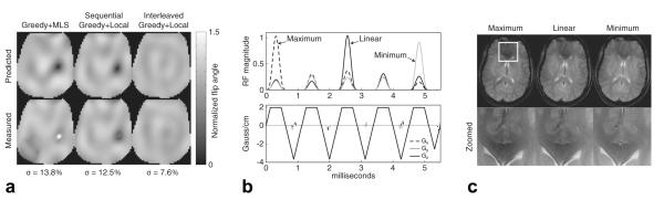
7 T experimental results (single frequency). a: Predicted and measured axial flip angle patterns for each pulse design method in a head phantom. Flip angle standard deviations are reported for the experimental patterns. The proposed interleaved greedy + local method produces the most uniform flip angle patterns. b,c: Demonstration of maximum/linear/minimum-phase pulse designs. b: The maximum RF magnitude across transmit channels is plotted for each pulse type (top) as well as the flyback gradient waveforms for the linear-phase pulse (bottom). c: Axial in vivo images for each pulse type are shown below as well as images of a zoomed region in the forebrain (which is outlined by the white box in the top maximum-phase image) in which the signal differences between pulse types are most apparent.
To investigate how the interleaved greedy + local method’s compute time depends on the number of transmit channels, the design grid size, the number of spokes, and the number of frequencies, pulse designs using and B0 maps measured in the ball phantom at 3T (which is described further below) were repeated over realistic ranges of these parameters. Designs were performed in MATLAB on a HP Z400 Linux workstation with a 3.2 GHz Intel Xeon CPU and 16 GB RAM (Hewlett Packard Co, Palo Alto, CA). For each parameter set, the design times were measured five times and averaged. The baseline pulse parameters were eight transmit channels, five spokes, a 64 × 64 design grid size, and one frequency at 0 Hz. The number of transmit channels was varied between 1, 2, 4, and 8 by combining neighboring channels of the eight channel body coil using RF phase shim weights. The grid dimensions were varied from 32 × 32 to 256 × 256 in steps of 32 × 32. The number of spokes was varied from 2 to 20 in steps of 2. The number of frequencies was varied between 1 and 5 to cover a bandwidth between 0 and −440 Hz, with both independent- and joint-phase desired flip angle patterns.
Experiments
Single-frequency experiments were carried out on the same 7T scanner to compare the flip angle patterns excited by pulses designed using the three methods. and B0 maps were measured in a 1% copper sulfate head phantom using the same sequences as used for the simulations, and five-spoke pulses (duration 7.5 ms) were designed using the same gradient trajectory and subpulse characteristics as in the simulations. The pulses were scaled to produce 45° flip angles, and their flip angle maps were measured using the actual flip-angle imaging (AFI) method (24) with repetition times of 50 and 250 ms and a two-dimensional Fourier transform (2DFT) readout. Additionally, axial gradient-recalled echo (GRE) brain images were acquired in a volunteer using three pulses designed using the interleaved greedy + local method with the DC spoke placed at the beginning, middle, and end of the pulse, to demonstrate the method’s ability to influence the effective TE period starting time. These three pulses will be loosely referred to as “maximum-phase,” “linear-phase,” and “minimum-phase,” respectively (16). These pulses were designed using time-bandwidth of 2 subpulses but otherwise the same subpulse and gradient parameters, yielding shorter 5.5 ms pulse durations. The center of k-space was acquired 12.25 ms after the end of the pulses.
Experiments were also performed to compare dual-frequency water/fat pulses designed with joint phase relaxation (14) using the sequential and interleaved greedy + local methods. Because the MLS method relaxes desired phase independently across frequencies, it could not be used to design these pulses. The experiments used a 28 cm 1% manganese chloride ball phantom and a volunteer in a 3T GE DVMR scanner equipped with eight excitation channels and a 16-element transverse electromagnetic (TEM) transmit body array with cross-diameter elements driven in tandem with opposite phase. An eight channel cardiac array was used for reception. All and B0 maps were measured using a 2DFT Bloch-Siegert acquisition and the delayed-TE method, with 64 × 64 matrix sizes and 48 cm field of views. The TE difference in the delayed-TE method was set equal to 2.3 ms to alias the fat frequency to 0 Hz. In the phantom experiment, pulses were designed by each of the three methods at frequencies 0 Hz (water) and −440 Hz (fat). The pulses comprised five spokes, whose slice-selective subpulses had a time-bandwidth product of 4 and excited 10 mm slices along gradient trapezoids with plateau amplitudes of 7 mT/m. The final gradient waveforms were designed to satisfy the system maximum gradient amplitude and slew rate limits of 23 mT/m and 120 mT/m/ms, respectively, yielding pulse durations of 10.25 ms. The pulses were scaled to excite 45° flip angles. The pulses were also compared to an RF magnitude- and phase-shimmed slice-selective pulse whose weights were calculated using the magnitude least-squares method with no RF regularization (6). Flip angle maps were measured using the AFI method, with repetition times of 30 and 270 ms and a 2DFT readout. Additionally, axial gradient-recalled echo (GRE) images were acquired in a volunteer’s abdomen and legs to qualitatively compare single- and dual-frequency spokes excitation pulses designed using the interleaved greedy + local method. Those pulses were designed using the same parameters as the phantom pulses.
RESULTS
Simulations
Figure 2a plots the flip angle standard deviations and RF powers of each method’s single-frequency pulses, averaged across slices and subjects. The interleaved greedy + local method usually achieves the lowest standard deviation among the three methods. Because the addition of each new spoke is guaranteed not to increase the design cost function which is a weighted sum of excitation nonuniformity and RF power metrics, the standard deviations of pulses designed by the interleaved greedy + local method decay smoothly as new spokes are added. Although not shown, the spread of standard deviations across slices and subjects is significantly narrower for the interleaved greedy + local method. Its pulses’ RF powers also vary smoothly as a function of the number of spokes. In contrast, in many instances the addition of a new spoke leads the greedy + MLS and sequential greedy + local methods to a local minimum with higher error and power. This is illustrated in Fig. 2b for those two methods and in two subjects. The left images in Fig. 2b show an instance where going from 11 to 12 spokes leads the greedy + MLS method to a solution with 10% higher standard deviation and two flip angle voids, while the homogeneity of the flip angle pattern produced by the interleaved greedy + local method improves slightly. The right images show that in another volunteer and slice, going from seven to eight spokes leads the sequential greedy + local method to a solution with 7.1% higher standard deviation and one flip angle void, while the homogeneity of the flip angle pattern produced by the interleaved greedy + local method again improves slightly. Figure 3a plots the flip angle standard deviations and RF powers of each method’s independent-phase multi-frequency pulses, again averaged across slices and subjects. Again the interleaved greedy + local method’s standard deviation and power curves vary more smoothly than the other two method’s curves, and it always achieves the lowest standard deviation among the three methods. The significantly higher power of the RF shim pulses is due to a lack of RF power regularization in the shim weight optimization; this large power drop between the RF shims and the two spoke pulses is also present in the single-frequency case but is less prominent there. Note that while the interleaved method’s RF power is always higher than the other methods’ powers, it varies smoothly as a function of the number of spokes and is never more than 2% higher than the power of the RF shim pulse. To illustrate the effective bandwidth of the single-frequency pulses in comparison to RF shimming and the multifrequency pulses, Fig. 3b plots the standard deviation of the flip angle patterns excited by the RF shim, single-frequency, and independent-phase multifrequency 5- and 20-spoke pulses designed with the interleaved method. The standard deviations at each frequency were again averaged across slices and subjects. If we define the effective bandwidth of the spokes pulses as the bandwidth over which the pulses excite more uniform flip angle patterns than the RF shim, then the effective bandwidth of the 5- and 20-spoke single-frequency pulses are approximately 150 and 70 Hz, respectively. Although not shown in the plot, the effective bandwidth of the 10-spoke single-frequency pulse was approximately 110 Hz, suggesting that the effective bandwidth of these pulses is approximately inversely proportional to the square root of pulse duration. Note that the multifrequency pulses excite more uniform patterns at all frequencies, compared to the RF shim pulse.
FIG. 2.

Single-frequency simulation results. a: Mean flip angle standard deviation and RF power as a function of the number of spokes in the pulses for single-frequency pulses. b: Examples of nonmonotonic behavior of greedy + MLS and sequential greedy + local methods, compared to the interleaved greedy + local method, in two subjects. The white arrows indicate large non-uniformities that appear with the addition of a new spoke.
FIG. 3.

Multifrequency simulation results. a: Flip angle standard deviation and RF power as a function of the number of spokes, for independent-phase multifrequency pulses (nine frequencies between −200 and 200 Hz). b: Bandwidth comparison of RF shimming, single-frequency 5- and 20-spokes pulses, and multifrequency 5- and 20-spokes pulses.
The compute times as a function of number of transmit channels were surprisingly flat: all measured times were between 5.05 and 6.12 s with a mean of 5.60 s. Further inspection revealed that while reducing the number of channels reduces the compute time for the RF subpulse weights, more iterations were required for fewer than eight channels, which approximately equalized the measured times. Compute times varied approximately linearly with the number of spatial locations, with average times of 6.8 s for a 32 × 32 grid and 78 s for a 256 × 256 grid. Compute times varied approximately quadratically with the number of spokes, with average times of 1.5 s for two spokes, 19.6 s for 10 spokes, and 82.4 s for 20 spokes. Compute times varied approximately linearly with the number of frequencies, and the times were slightly shorter for independent phase relaxation which had average times of 5.6 s for one frequency and 26.1 s for five frequencies. The jointly relaxed designs had average times of 5.6 s for one frequency and 28.4 s for five frequencies.
Experiments
Figure 4a shows predicted and measured flip angle maps in the head phantom at 7T. The greedy + MLS and sequential greedy + local pulses both excited flip angle patterns containing voids, which erroneously appear brighter in the measured maps due to noise amplification by AFI’s image division, while the interleaved greedy + local pulse excited a flip angle pattern that was significantly more uniform with no voids. The predicted and measured flip angle patterns are in good agreement. The RF pulse plots in Fig. 4b show that RF power is concentrated in the first spoke for maximum-phase pulses, in the middle spoke for linear-phase pulses, and in the last spoke for minimum-phase pulses. These spoke locations were at DC in each case. Starting the TE period in the middle of these DC subpulses yields TE’s of 17.5 ms (maximum phase), 15.25 ms (linear phase), and 13 ms (minimum phase). Axial images obtained using these pulses (Fig. 4c) confirm that the earlier in the pulse the DC location is visited, the more signal loss is incurred due to decay and through-plane dephasing.
Figure 5a shows measured flip angle maps in the ball phantom at 3T. The interleaved greedy + local method produces the most uniform flip angle patterns, while the sequential greedy + local method does not perform as well as RF shimming. Figure 5b shows the in vivo images obtained using single-frequency and dual-frequency spokes pulses designed using the interleaved greedy + local method. The single-frequency pulses excite uniform flip angles in muscle and other aqueous tissue, but highly nonuniform flip angles in fat, where multiple signal voids are present. The dual-frequency pulses excite fat much more uniformly.
FIG. 5.

3 T joint-phase multifrequency experimental results. a: Measured axial flip angle maps and standard deviations (calculated jointly in water (0 Hz) and fat (−440 Hz)) for each pulse design method in a ball phantom. b: Comparison of single- and dual-frequency spokes pulses designed using the proposed method. The white arrows indicate areas of low signal where the single-frequency pulses fail to excite fat coherently.
DISCUSSION
The interleaved greedy and local spokes pulse design method inherits all desirable properties of local and sparse approximation-based pulse design methods. From local methods it inherits the flexibility to account for off-resonance and to design pulses that excite homogeneous flip angle patterns across multiple frequencies. The inclusion of a measured off-resonance map in the pulse design substantially reduces the excitation error (17) of parallel transmit pulses, and is a significant advantage of local and interleaved greedy and local methods over sparse approximation-based methods. From sparse approximation-based methods, the interleaved greedy and local method inherits the ability to efficiently search over a large swath of candidate kx–ky locations for each spoke. Given a desired flip angle variance threshold, the interleaved greedy and local method can exit once the flip angle variance falls below that threshold, which may occur before all spokes are added, yielding a shorter and therefore more robust pulse. Additionally, as in greedy spokes pulse design the intermediate pulses with fewer than the final number of spokes are the same pulses as would have been designed had that number of spokes been specified in the first place. This is desirable since the user would not be required to redesign the pulses should they decide to use fewer spokes than was initially specified. The method also simplifies selection of the number of spokes in light of concerns about through-slice signal dropout (25) and decay during the pulse. This is because the method allows the user to place the DC spoke at the beginning of the pulse so that (for a fixed TE) the TE period starts at the beginning of the pulse, and the number of spokes can simply be set equal to the number that can be accommodated in the TE period before the signal readout starts. For the selected TE, the resulting sequence’s sensitivity to decay and through-plane signal dropout would then be approximately independent of the number of spokes.
The method may be extended or improved in multiple ways:
While the multifrequency design examples presented here were all-pass designs, the method can be used to design pulses which excite one band of frequencies and suppress another (26).
The design examples presented here focused on homogeneous excitation of the entire transverse plane in the body, but the method could also be used to design reduced-field of view spokes pulses.
As is the case for many spokes and parallel transmit pulse design algorithms, there are several opportunities to parallelize the proposed method to reduce compute times, e.g., by evaluating multiple candidate kx–ky locations in parallel within the greedy component.
Similarly to Setsompop et al.’s broadband pulse design method (7), the interleaved greedy and local method could be used to design slab-selective pulses by including maps at multiple z locations in the slab. In this case, the desired phase patterns would become three-dimensional.
The method could be generalized to optimize the full slice-selective pulse waveforms for each channel and spoke, rather than the subpulse weights. This could be useful to reduce excited flip angle pattern distortions resulting from spectral phase evolution during each spoke (27) or to enable a more complete compensation of variations in the slice dimension, e.g., in slab-selective pulse design. This would, however, significantly increase the computational cost of the algorithm, as the set of RF pulse variables would become much larger, and the target flip angle patterns would become three-dimensional.
As an alternative to the heuristic RF power regularization strategy described here, at each update multiple solutions could be computed across a range of λ values to find the λ corresponding to the knee of the excitation accuracy vs. RF power tradeoff curve (L-curve) (28). The knee of the L-curve is the point where a small decrease in one objective can only be accomplished by a large increase in the other, and typically represents a good compromise between the objectives (19). While this improvement would come at the cost of increased compute time, the computations could be parallelized across λ values.
Finally, given the required electric field, tissue density and conductivity maps, the interleaved method could accommodate specific absorption rate constraints in the updates (29).
CONCLUSION
The proposed interleaved greedy and local spokes pulse design method was demonstrated in 7T head simulations and 7 and 3T experiments to be robust and flexible in the design of single- and multifrequency pulses. In 7T head simulations, the method excited flip angle patterns that were consistently more homogeneous than pulses designed with greedy + MLS and sequential greedy + local methods and had comparable RF power. In particular, the addition of each new spoke is guaranteed not to increase the cost (Eqs. [4] and [5]), resulting in regular flip angle standard deviation and RF power curves as a function of the number of spokes. The 7T simulations and experiments showed that the interleaved greedy and local method was better able to avoid flip angle voids than the other two methods. The interleaved greedy and local method inherits the desirable qualities of both local and sparse approximation-based pulse design methods, resulting in a spokes pulse design method that is more robust and flexible than either class of methods.
ACKNOWLEDGMENT
The authors are thankful to Chao Ma for assistance in implementing the SOLO method.
REFERENCES
- 1.Saekho S, Yip CY, Noll DC, Boada FE, Stenger VA. Fast-kz three-dimensional tailored radiofrequency pulse for reduced B1 inhomogeneity. Magn Reson Med. 2006;55:719–724. doi: 10.1002/mrm.20840. [DOI] [PMC free article] [PubMed] [Google Scholar]
- 2.Yip CY, Fessler JA, Noll DC. Advanced three-dimensional tailored RF pulse for signal recovery in T2*-weighted functional magnetic resonance imaging. Magn Reson Med. 2006;56:1050–1059. doi: 10.1002/mrm.21048. [DOI] [PubMed] [Google Scholar]
- 3.Nielsen JF, Yoon D, Noll DC. Suppression of banding and transient signal oscillations in balanced SSFP using a spoiled RF pre-phasing approach. Proceedings of the 18th Scientific Meeting of International Society for Magnetic Resonance in Medicine; Stockholm. 2010. p. 77. [Google Scholar]
- 4.Pauly JM, Nishimura DG, Macovski A. A k-space analysis of small-tip-angle excitation. J Magn Reson. 1989;81:43–56. doi: 10.1016/j.jmr.2011.08.008. [DOI] [PubMed] [Google Scholar]
- 5.Zhang Z, Yip CY, Grissom W, Noll DC, Boada FE, Stenger VA. Reduction of transmitter B1 inhomogeneity with transmit SENSE slice-select pulses. Magn Reson Med. 2007;57:842–847. doi: 10.1002/mrm.21221. [DOI] [PMC free article] [PubMed] [Google Scholar]
- 6.Setsompop K, Wald LL, Alagappan V, Gagoski BA, Adalsteinsson E. Magnitude least squares optimization for parallel radio frequency excitation design demonstrated at 7 Tesla with eight channels. Magn Reson Med. 2008;59:908–915. doi: 10.1002/mrm.21513. [DOI] [PMC free article] [PubMed] [Google Scholar]
- 7.Setsompop K, Alagappan V, Gagoski BA, Potthast A, Hebrank F, Fontius U, Schmitt F, Wald LL, Adalsteinsson E. Broadband slab selection with mitigation at 7T via parallel spectral-spatial excitation. Magn Reson Med. 2009;61:493–500. doi: 10.1002/mrm.21834. [DOI] [PMC free article] [PubMed] [Google Scholar]
- 8.Tropp JA, Gilbert AC, Strauss MJ. Algorithms for simultaneous sparse approximation. Part I: Greedy pursuit. Sig Proc. 2006;86:572–588. [Google Scholar]
- 9.Tropp JA. Algorithms for simultaneous sparse approximation. Part II: Convex relaxation. Sig Proc. 2006;86:589–602. [Google Scholar]
- 10.Chen D, Bornemann F, Vogel MW, Sacolick LI, Kudielka G, Zhu Y. Sparse parallel transmit pulse design using orthogonal matching pursuit method. Proceedings of the 17th Scientific Meeting of International Society for Magnetic Resonance in Medicine; Honolulu. 2009. p. 171. [Google Scholar]
- 11.Ma C, Xu D, King KF, Liang ZP. Joint design of spoke trajectories and RF pulses for parallel excitation. Magn Reson Med. 2011;65:973–985. doi: 10.1002/mrm.22676. [DOI] [PubMed] [Google Scholar]
- 12.Yoon D, Maleh R, Gilbert AC, Fessler JA, Noll DC. Fast selection of phase encoding locations in parallel excitation. Proceedings of the 17th Scientific Meeting of International Society for Magnetic Resonance in Medicine; Honolulu. 2009. p. 2595. [Google Scholar]
- 13.Zelinski AC, Wald LL, Setsompop K, Goyal VK, Adalsteinsson E. Sparsity-enforced slice-selective MRI RF excitation pulse design. IEEE Trans Med Imaging. 2008;27:1213–1229. doi: 10.1109/TMI.2008.920605. [DOI] [PMC free article] [PubMed] [Google Scholar]
- 14.Kerr AB, Etezadi-Amoli M, Fautz H-P, Vogel MW, Gross P, Zhu Y, Pauly JM. Dual-band RF shimming at high-field with parallel excitation. Proceedings of the 17th Scientific Meeting of International Society for Magnetic Resonance in Medicine; Honolulu. 2008. p. 617. [Google Scholar]
- 15.Yip CY, Grissom W, Fessler JA, Noll DC. Joint design of trajectory and RF pulses for parallel excitation. Magn Reson Med. 2007;58:598–604. doi: 10.1002/mrm.21262. [DOI] [PubMed] [Google Scholar]
- 16.Pauly JM, Le Roux P, Nishimura DG, Macovski A. Parameter relations for the Shinnar-Le Roux selective excitation pulse design algorithm. IEEE Trans Med Imaging. 1991;10:53–65. doi: 10.1109/42.75611. [DOI] [PubMed] [Google Scholar]
- 17.Grissom WA, Yip CY, Zhang Z, Stenger VA, Fessler JA, Noll DC. Spatial domain method for the design of RF pulses in multicoil parallel excitation. Magn Reson Med. 2006;56:620–629. doi: 10.1002/mrm.20978. [DOI] [PubMed] [Google Scholar]
- 18.Funai AK, Fessler JA, Yeo D, Olafsson VT, Noll DC. Regularized field map estimation in MRI. IEEE Trans Med Imaging. 2008;27:1484–1494. doi: 10.1109/TMI.2008.923956. [DOI] [PMC free article] [PubMed] [Google Scholar]
- 19.Boyd S, Vandenberghe L. Convex optimization. Cambridge University Press; Cambridge, UK: 2004. [Google Scholar]
- 20.Sacolick LI, Wiesinger F, Hancu I, Vogel MW. B1 mapping by Bloch-Siegert shift. Magn Reson Med. 2010;63:1315–1322. doi: 10.1002/mrm.22357. [DOI] [PMC free article] [PubMed] [Google Scholar]
- 21.Khalighi MM, Rutt BK, Saranathan M, Kerr AB. RF pulse optimization for Bloch-Siegert mapping. Proceedings of the 19th Scientific Meeting of the International Society for Magnetic Resonance in Medicine; Montreal. 2011. p. 4431. [Google Scholar]
- 22.Khalighi MM, Glover GH, Pandit P, Hinks RS, Kerr AB, Saranathan M, Rutt BK. Single-shot spiral based Bloch-Siegert mapping. Proceedings of the 19th Scientific Meeting of International Society for Magnetic Resonance in Medicine; Montreal. 2011. p. 578. [Google Scholar]
- 23.Schneider E, Glover G. Rapid in vivo proton shimming. Magn Reson Med. 1991;18:335–347. doi: 10.1002/mrm.1910180208. [DOI] [PubMed] [Google Scholar]
- 24.Yarnykh VL. Actual flip-angle imaging in the pulsed steady state: a method for rapid three-dimensional mapping of the transmitted radiofrequency field. Magn Reson Med. 2007;57:192–200. doi: 10.1002/mrm.21120. [DOI] [PubMed] [Google Scholar]
- 25.Lipschutz B, Friston KJ, Ashburner J, Turner R, Price CJ. Assessing study-specific regional variations in fMRI signal. Neuroimage. 2001;13:392–398. doi: 10.1006/nimg.2000.0687. [DOI] [PubMed] [Google Scholar]
- 26.Malik SJ, Larkman DJ, O’Regan DP, Hajnal JV. Subject-specific water-selective imaging using parallel transmission. Magn Reson Med. 2010;63:988–997. doi: 10.1002/mrm.22260. [DOI] [PubMed] [Google Scholar]
- 27.Cunningham CH, Chen AP, Lustig M, Hargreaves BA, Lupo J, Xu D, Kurhanewicz J, Hurd R, Pauly JM, Nelson SJ, Vigneron DB. Pulse sequence for dynamic volumetric imaging of hyperpolarized metabolic products. J Magn Reson. 2008;193:139–146. doi: 10.1016/j.jmr.2008.03.012. [DOI] [PMC free article] [PubMed] [Google Scholar]
- 28.Sbrizzi A, Hoogduin H, Lagendijk JJ, Luijten P, Sleijpen GLG, van den Berg CAT. Time efficient design of multi dimensional RF pulses: application of a multi shift CGLS algorithm. Magn Reson Med. 2011;66:879–885. doi: 10.1002/mrm.22863. [DOI] [PubMed] [Google Scholar]
- 29.Brunner DO, Pruessmann KP. Optimal design of multiple-channel RF pulses under strict power and SAR constraints. Magn Reson Med. 2010;63:1280–1291. doi: 10.1002/mrm.22330. [DOI] [PubMed] [Google Scholar]