Abstract
High voltage electrical fields and low production rate limit electrospinning, the electrical charging of polymer liquids, as a means of nanofiber fabrication. Here, we show a facile method of fabrication of aligned 3D nanofiber structures by utilizing high speed, rotating polymer solution jets to extrude fibers. Termed rotary jet-spinning, fiber morphology, diameter and web porosity can be controlled by varying nozzle geometry, rotation speed, and polymer solution properties. We demonstrate the utility of this technique for tissue engineering by building anisotropic arrays of biodegradable polymer fibers and seeding the constructs with neonatal rat ventricular cardiomyocytes. The myocytes used the aligned fibers to orient their contractile cytoskeleton and to self-organize into a beating, multicellular tissue that mimics the laminar, anisotropic architecture of the heart muscle. This technique may prove advantageous for building uniaxially-aligned nanofiber structures for polymers which are not amenable to fabrication by electrospinning.
Keywords: Nanofiber fabrication, rotary-jet spinning system, fiber alignment, 3-dimensional assembly, cardiac tissue engineering, protein nanofibers
Self-assembly, phase separation and electrospinning are commonly used to generate nanofibrous scaffolds 1. Among these, electrospinning is the most popular strategy, producing ultra-fine fibers by electrically charging a droplet of polymer liquid 2–11. In spite of the versatility and popularity of electrospinning, high voltage electrical fields, imprecise control over fiber orientation, sensitivity to variability in solution conductivity, low production rate and difficulty in fabricating 3D structures limit its application. There are few strategies to expand the versatility of electrospinning 12–13, however, the need for reliable methods to generate well characterized and aligned micro- to nano-scale polymeric fibers persists.
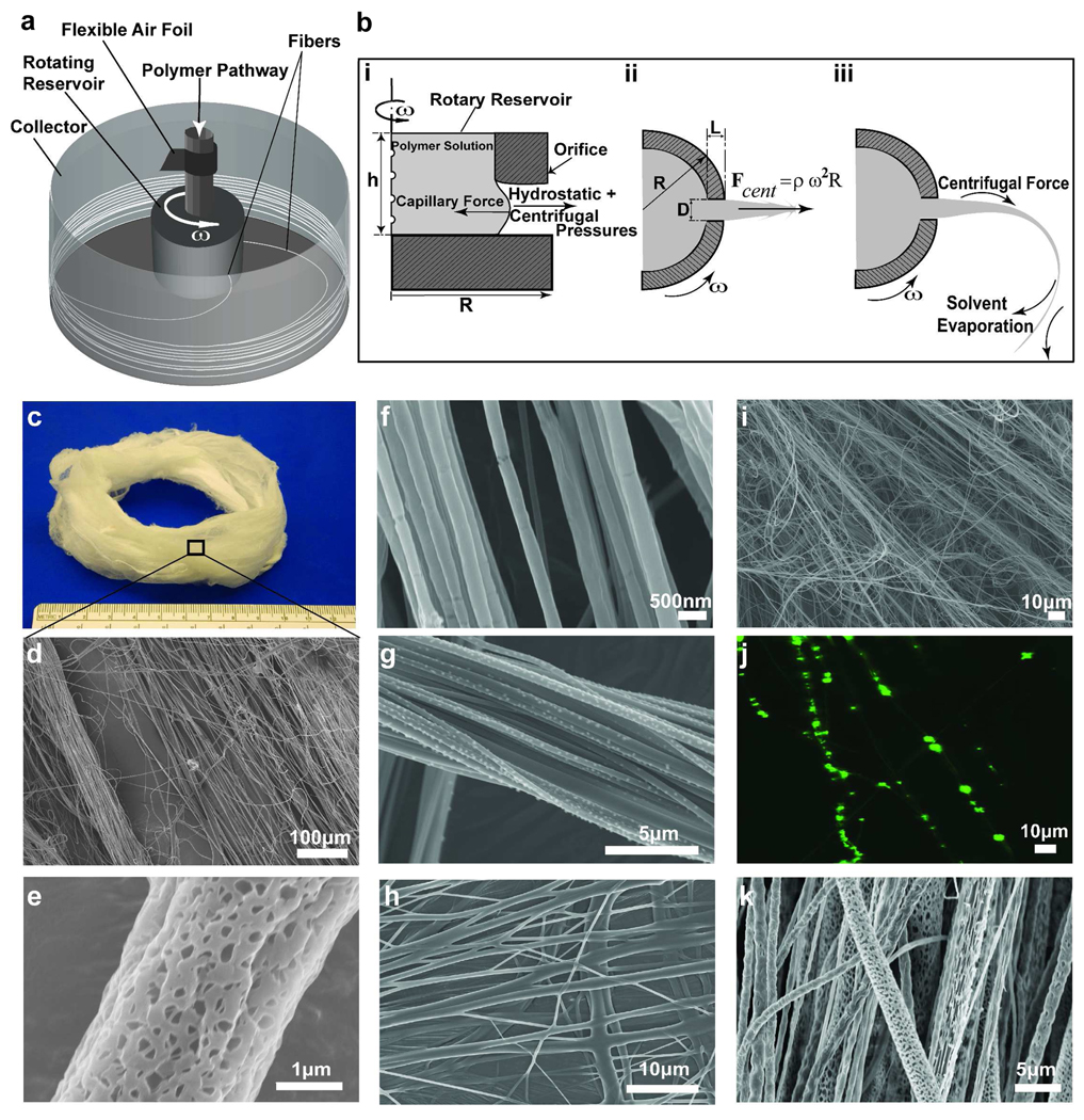
We hypothesized that we could produce nano-scale fibers by exploiting a high speed rotating nozzle to form a polymer jet which undergoes extensive stretching before solidification (Figure 1a). Termed rotary jet-spinning (RJS), the RJS system consisted of a reservoir with two side wall orifices that was attached to the shaft of a motor with controllable rotation speed. To facilitate the fiber collection a flexible air foil is placed on the shaft above the reservoir. The polymer solution was continuously fed to the reservoir at a rate sufficient to maintain a constant hydrostatic pressure and continuous flow. The resulting fibers were collected either on a stationary, surrounding cylindrical collector or on coverslips which were held against the collector wall. The fiber production process is composed of (i) jet-initiation to induce flow of the polymer solution through the orifice, (ii) jet-extension to increase surface area of the propelled polymer stream, and (iii) solvent evaporation to solidify and shrink the polymer jet. During the first step (Figure 1b-i), a combination of hydrostatic pressure and centrifugal pressure at the far end of capillary 14 exceeds the flow-resistant capillary forces and propels the polymer liquid through the nozzle capillary as a jet. The outward radial centrifugal force stretches the polymer jet as it is projected towards the collector wall (Figure 1b-ii), but the jet travels in a curled trajectory due to rotation-dependent inertia. Stretching of the extruded polymer jet is critical in reducing jet diameter over the distance from the nozzle to the collector. Concurrently, the solvent in the polymer solution evaporates, solidifying and contracting the jet (Figure 1b-iii). The solvent evaporation rate depends on its volatility. If the solvent is highly volatile, the jets form thicker fibers as the rapidly evaporating solvent potentiates rapid solidification, hindering the jet extension. The primary challenges in this process are optimizing the polymer solution properties (viscoelasticity and surface tension), solvent volatility, capillary diameter, and collector radius to not only produce ultra fine fibers but also prevent jet rupture and the formation of droplets due to Plateau-Rayleigh instability 15. The jet break-up may be estimated by the capillary number, defined as the ratio of Weber number (We) to Reynolds number (Re), Ca = We / Re, which characterizes the ratio of the viscous force to the surface tension force 15. Here We = ρU2 D / γ and Re = ρUD / η where ρ, η and γ are density, dynamic viscosity and surface tension of polymer solution, respectively, U is the polymer jet exit speed based on a stationary frame (see Supporting Information for measurement of jet speed) and D is the orifice diameter. A lower capillary number results in shorter jet length and earlier jet break-up to isolated droplets 15.
FIGURE 1.
Schematic of rotary jet-spinning process. (a) Rotary jet-spinning consisted of a perforated reservoir (internal volume of 700 µL and external diameter of 12.5 mm) with two side wall orifices (orifice diameter of 340 µm and length to diameter ratio of 9) which rotates about its vertical axis in the center of a stationary collector; the polymer solution continuously feeds into the reservoir and produces fibers that are deposited over the collector (diameter of 300 mm). (b) Magnified view of the presumed formation mechanism of nano-scale fibers through RJS system, (i) jet-initiation, (ii) jet-extension and (iii) solvent evaporation. (c) Photographic image of 3D nanofiber structures produced by rotary jet-spinning, 8 wt% PLA in CHCl3 at 12,000 rpm rotation speed. (d) Scanning electron micrograph (SEM) of fibers in 1C. (e) PLA fibers (10 wt% PLA in CHCl3 at 12,000 rpm rotation speed) produced with expedited solvent evaporation and high humidity (more than 55% R.H.). (f) SEM of 5 wt% PEO in water spun at 12,000 rpm. (g) SEM of 8 wt% PAA in water at 50% neutralization degree spun at 12,000 rpm, (h) SEM of 8 wt% PAA in water at 100% neutralization degree spun at 12,000 rpm. (i) SEM of 14 wt% gelatin in 20 v/v% acetic acid spun at 12,000 rpm. (j) The laser scanning confocal image of fiber encapsulated fluorescent polystyrene beads (0.2 µm diameter). (k) SEM of emulsion of gelatin in PLA spun at 12,000 rpm rotation speed.
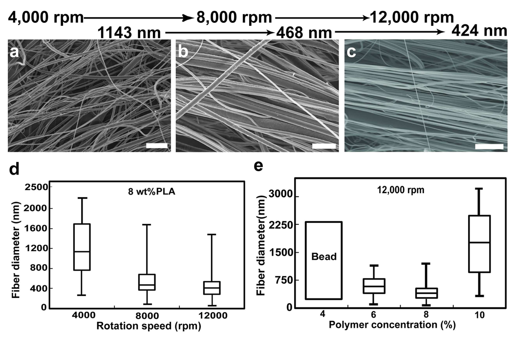
As proof-of-principle, we produced rotary jet-spun fibers from a wide variety of synthetic and naturally occurring polymers. We produced nanofibers from poly (lactic acid) (PLA) in chloroform (Figure 1c–e), poly (ethylene oxide) in water (Figure 1f), poly (acrylic acid) in water at different conductivities (neutralized with sodium hydroxide) (Figure 1g and 1h), gelatin in mild acetic acid (Figure 1i), an emulsion of gelatin in PLA (Figure 1j) and PEO doped with fluorescent spherical beads (Figure 1k) (refer to Supporting Information for more details on sample preparation). These data suggest that RJS is a rapid and facile technique of nanofiber fabrication without electrical propulsion and is capable of fabricating 3D aligned nanofiber structures from a variety of polymers. To study the sensitivity of RJS fiber fabrication to various production variables, we focused on producing PLA fibers (see Table 1 for composition details). As shown in Figure 2, continuous aligned PLA fibers with diameters ranging from 50–3500 nm can be produced. To demonstrate the ability to tailor the nanofiber morphology, we produced nanofibers at different rotation speeds. By increasing the rotation speed from 4,000 to 12,000 rpm, the fiber diameter (median ± median standard error) dropped from 1143 ± 50 to 424 ± 41 nm (Figure 2a–c).
Table 1.
Composition and parameter values of all PLA solutionsa
| Conc wt% |
Rotation Rpm |
η0 mPa˙s |
γ mN˙m−1 |
ρ g˙cm−3 |
U cm/s |
We | Re | Ca | Fiber feature | Fiber Diameter Parameters (nm) |
||
|---|---|---|---|---|---|---|---|---|---|---|---|---|
| Q1 | Q2 | Q3 | ||||||||||
| 10 | 12,000 | 282 | 27 | 1.54 | 398 | 150 | 3.8 | 40 | Continuous Fiber | 833 | 1630 | 2168 |
| 4,000 | 133 | 18 | 3.1 | 6 | Continuous Fiber | 782 | 1143 | 1740 | ||||
| 8 | 8,000 | 113 | 27 | 1.52 | 266 | 68 | 6.1 | 11 | Continuous Fiber | 369 | 468 | 679 |
| 12,000 | 399 | 153 | 9.2 | 17 | Continuous Fiber | 285 | 424 | 742 | ||||
| 6 | 4,000 | 46 | 26 | 1.51 | 133 | 17 | 7.5 | 2.4 | Fiber + Many beads | 255 | 571 | 825 |
| 12,000 | 399 | 158 | 23 | 7 | Fiber + Few beads | 421 | 566 | 795 | ||||
| 4 | 12,000 | 21 | 26 | 1.50 | 400 | 158 | 51 | 3 | Only Beads | N/A | N/A | N/A |
| 8* | 12,000 | 113 | 27 | 1.52 | 399 | 285 | 17 | 17 | Continuous Fiber | 612 | 962 | 1299 |
Q1, Q2 and Q3 are first, second and third quartile of fiber diameter distribution which represent 25th, 50th and 75th percentile, respectively. η0, γ and ρ are shear viscosity, surface tension and density of the solution, U is the jet speed, We, Re and Ca are Weber number, Reynolds number and capillary number, respectively. Orifice geometry for all samples was D=340µm, L:D=9 except for the (*) was D=650µm, L:D=4.5. Fiber diameters can be tailored with the orifice diameters (see Supporting Information for more detail on orifice geometry). These data suggest that by decreasing the length to diameter ratio of the orifice, the pressure drop at the orifice decreases and the rate of solution outflow increases, resulting in larger diameter fibers.
FIGURE 2.
Fiber morphology and diameter distribution for 8 wt% PLA solution spun at different rotation speeds, Spun at (a) 4,000 rpm, (b) 8,000 rpm. (c) 12,000 rpm, scale bar is 10µm. (d) Diameter distribution of all samples in box plots, the horizontal lines inside the boxes represent the median values and the limits of the box denote the upper and lower quartiles. The maximum and minimum values delimit the bars. (e) Diameter distribution of PLA samples at different polymer concentration spun at 12,000 rpm.
We hypothesize that the mechanism of RJS fiber formation is the optimization of the competing centrifugal forces and jet surface tension. The surface tension causes jet instability and bead formation16 while the centrifugal force accelerates a slender liquid stream where solvent evaporation and polymer chain elongation occur simultaneously. Thus, higher centrifugal force induces greater extension and thinning of the polymer jet which results in thinner fiber diameters. To test this hypothesis, first we varied the rotation speed while maintaining a constant PLA solution concentration. The centrifugal force per solution volume increases significantly with rotation speed, while the surface tension remains the same (Table 1 and see Supporting Information for surface tension measurement). The fiber diameter distribution (Figure 2d) is much wider at lower rotation speed and the probability of bead formation is higher. Next, we held the rotation speed constant while varying the polymer concentration in the solvent. We hypothesized that the surface tension of the polymer solution and its tendency to induce beading could be compensated for by varying the polymer concentration. When we held the rotation speed constant, at low polymer concentrations (4 wt%) RJS resulted in polymer beads. As we increased the polymer concentration (c) (4 wt%< c <10 wt%), the increased polymer chain entanglement stabilized the jet resulting in fiber formation. This data demonstrates that fiber formation is a function of the polymer concentration where an optimal range of concentrations increases the likelihood of polymer chain entanglement 17, resisting beading and resulting in fine fibers. Beyond this optimal range (10 wt% and higher), the higher solution viscosity limits solvent evaporation and necking, resulting in thicker fibers.
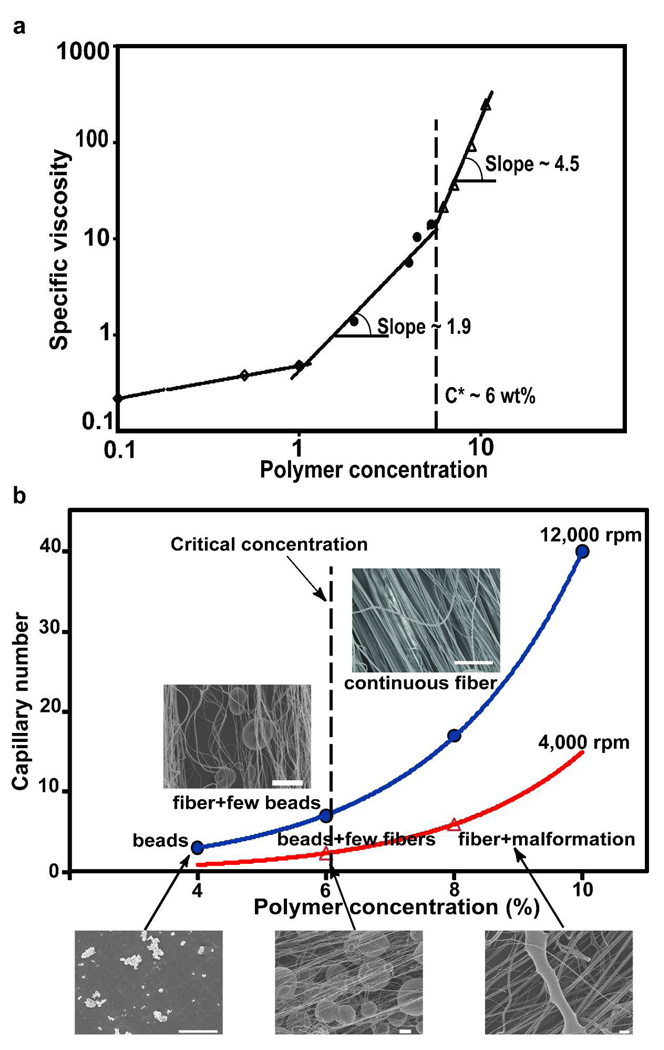
An additional contributor to fiber formation is polymer chain entanglement density. As the polymer concentration increases, a deformable entangled network of polymer chains forms as a direct consequence of chain overlap. In low concentration (c) polymer solutions, lower than critical concentration value, c*, (c≪c*) chain overlapping is absent. As the polymer concentration is increased (c→c*), chain entanglement is still insufficient for formation of bead-free fibers 17–18. At solution concentrations above the critical concentration (c> c*), sufficient chain entanglement produces uniform continuous fibers without beads. We measured the specific viscosity of polymer solutions as a function of concentration (see Supporting Information for specific viscosity calculation). As depicted in Figure 3a, changes in the slope marked the onset of the semidilute unentangled, entangled and concentrated regimes, the latter (c*) occurring at 6 wt% polymer solution concentration.
FIGURE 3.
(a) Specific viscosity versus polymer concentration profile for PLA solutions. Changes in the slope marked the onset of the semidilute unentangled, semidilute entangled and concentrated regimes. The c* was found to be 6 wt%. (b) The relationship between capillary number, polymer concentration and fiber morphology spun at different rotation speeds. Scale bar is 20µm.
We asked how the capillary number (Ca) and polymer solution concentrations affect the quality of fiber production. In this case, we define the highest production quality as bead-free fibers. The Ca number represents the magnitude of the centrifugally-induced shearing forces relative to the surface tension 19. We observed an increased likelihood of continuous fibers at high Ca numbers (Figure 3b). As expected, for c<c*, RJS produced only beads, however, for c>c*, chain entanglement was sufficient to potentiate fiber formation. At lower rotation speeds and Ca, fiber malformations were occasionally present (Figure 3b), however, with higher Ca and rotation speeds, higher quality fiber production was achievable. These data suggest that by increasing the rotation speed, the polymer jet travels faster and stretches rapidly, enhancing solvent evaporation. Rapid solvent evaporation increases polymer concentration and solution viscosity, the latter due to chain entanglement. This stabilizes the jet and resists surface tension-induced bead formation.
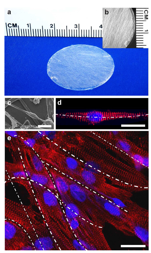
To test the ability of RJS to produce tissue engineering scaffolds, we prepared anisotropic, fibrous constructs (Figure 4a, b). Chemically dissociated neonatal rat ventricular myocytes were seeded on the constructs where they bound to, and spontaneously aligned with the fibers (Figure 4c). Individual myocytes organized their contractile cytoskeleton with respect to the external cue provided by the extracellular fibers, as indicated by the alignment of the sarcomeric Z lines perpendicular to the fiber alignment (Figure 4d). As depicted in the example in Figure 4e, multicellular constructs self-organized with respect to the fibers, forming beating, anisotropic muscle with aligned and elongated myocytes and ordered myofibrils, as seen previously observed with other cardiac tissue engineering techniques 20–21. These examples suggest that RJS is a simple means of forming anisotropic scaffolds of biodegradable nano- and microfibers made from synthetic and natural polymers.
FIGURE 4.
(a) Photographic image of PLA scaffold affixed to a 25 mm glass coverslip. (b) Stereo microscope image of PLA scaffold shows macroscale alignment of fibers. (c) SEM of PLA fibers with a cell attached to and encompassing the fiber bundle. Median fiber diameter is 1.43 ± 0.55 µm. (d) Laser scanning confocal image of a cardiomyocyte attached to and extending along a gelatin nanofiber. Median diameter of gelatin fibers is 515 ± 27 nm (white dashed line). (e) Laser scanning confocal image of engineered anisotropic cardiac muscle on a RJS-produced PLA scaffold (fibers are 1.43 ± 0.55 µm diameter, white dashed lines). Nuclear DNA is stained in blue, α-actinin at the sarcomeric Z-lines is red. Scale bars are 20 µm.
In conclusion, we have developed an effective technique for the generation of continuous fibers and nonwoven fabrics with nanometer size fiber diameters by using high-speed mechanical rotation of polymeric solutions through a perforated rotary reservoir. Rotary jet-spinning has several advantages in comparison with other nanofiber fabrication methods: a) the technique does not require high voltage electric fields, b) the apparatus is simple to implement, c) nanofiber structures can be fabricated into an aligned 3D structure or any arbitrary shape by varying the collector geometry, d) fiber morphology (beaded, textured, or smooth), fiber diameters and web porosity can be manipulated by altering the process variables, e) fiber fabrication is independent of solution conductivity, f) RJS is easily applicable to polymer emulsions and suspensions, and g) RJS is capable of substantially higher production rates as compared to standard electrospinning.
Supplementary Material
Acknowledgment
We acknowledge financial support of this work from Harvard University Nanoscale Science and Engineering Center (NSEC), Harvard Materials Research Science and Engineering Center (MRSEC), Harvard Center for Nanoscale Systems (CNS), Wyss Institute for Biologically-Inspired Engineering and NIH R01HL079126-01A2. HAM acknowleges the National Science Foundation Graduate Research Fellowship Program. We thank Megan McCain and Mark Brigham for carrying out cell harvests.
Footnotes
Supporting Information:
The materials and fabrication method of RJS technique is explicitly detailed. This material is available free of charge via the Internet at http://pubs.acs.org.
REFERENCES AND NOTES
- 1.Madurantakam PA, Rodriguez IA, Cost CP, Viswanathan R, Simpson DG, Beckman MJ, Moon PC, Bowlin GL. Biomaterials. 2009;30(29):5456–5464. doi: 10.1016/j.biomaterials.2009.06.043. [DOI] [PubMed] [Google Scholar]
- 2.Xie JW, Li XR, Xia YN. Macromolecular Rapid Communications. 2008;29(22):1775–1792. doi: 10.1002/marc.200800381. [DOI] [PMC free article] [PubMed] [Google Scholar]
- 3.Reneker DH, Yarin AL, Zussman E, Xu H. Advances in Applied Mechanics, Vol 41. 2007;41:43–195. [Google Scholar]
- 4.Dzenis Y. Science. 2004;304(5679):1917–1919. doi: 10.1126/science.1099074. [DOI] [PubMed] [Google Scholar]
- 5.Rutledge GC, Yu JH. Encyclopedia of Polymer Science and Technology. New Jersey: John Wiley & Sons; 2007. Electrospinning. [Google Scholar]
- 6.Krogman KC, Lowery JL, Zacharia NS, Rutledge GC, Hammond PT. Nature Materials. 2009;8(6):512–518. doi: 10.1038/nmat2430. [DOI] [PubMed] [Google Scholar]
- 7.Pham QP, Sharma U, Mikos AG. Tissue Engineering. 2006;12(5):1197–1211. doi: 10.1089/ten.2006.12.1197. [DOI] [PubMed] [Google Scholar]
- 8.Boland ED, Wnek GE, Simpson DG, Pawlowski KJ, Bowlin GL. Journal of Macromolecular Science-Pure and Applied Chemistry. 2001;38(12):1231–1243. [Google Scholar]
- 9.Teo WE, Ramakrishna S. Nanotechnology. 2006;17(14):R89–R106. doi: 10.1088/0957-4484/17/14/R01. [DOI] [PubMed] [Google Scholar]
- 10.Li D, Xia YN. Advanced Materials. 2004;16(14):1151–1170. [Google Scholar]
- 11.Greiner A, Wendorff JH. Angewandte Chemie-International Edition. 2007;46(30):5670–5703. doi: 10.1002/anie.200604646. [DOI] [PubMed] [Google Scholar]
- 12.Weitz RT, Harnau L, Rauschenbach S, Burghard M, Kern K. Nano Letters. 2008;8(4):1187–1191. doi: 10.1021/nl080124q. [DOI] [PubMed] [Google Scholar]
- 13.Arumuganathar S, Jayasinghe SN. Biomacromolecules. 2008;9(3):759–766. doi: 10.1021/bm701322k. [DOI] [PubMed] [Google Scholar]
- 14.Ducree J, Haeberle S, Lutz S, Pausch S, von Stetten F, Zengerle R. Journal of Micromechanics and Microengineering. 2007;17(7):S103–S115. [Google Scholar]
- 15.Oliveira MSN, Yeh R, McKinley GH. Journal of Non-Newtonian Fluid Mechanics. 2006;137(1–3):137–148. [Google Scholar]
- 16.Lord R. Proceedings of the London Mathematical Society. 1878;s1–10(1):4–13. [Google Scholar]
- 17.Shenoy SL, Bates WD, Frisch HL, Wnek GE. Polymer. 2005;46(10):3372–3384. [Google Scholar]
- 18.Wang C, Chien HS, Yan KW, Hung CL, Hung KL, Tsai SJ, Jhang HJ. Polymer. 2009;50(25):6100–6110. [Google Scholar]
- 19.Eggers J. Reviews of Modern Physics. 1997;69(3):865–929. [Google Scholar]
- 20.Feinberg AW, Feigel A, Shevkoplyas SS, Sheehy S, Whitesides GM, Parker KK. Science. 2007;317(5843):1366–1370. doi: 10.1126/science.1146885. [DOI] [PubMed] [Google Scholar]
- 21.Alford PW, Feinberg AW, Sheehy SP, Parker KK. Biomaterials. 2010;31(13):3613–3621. doi: 10.1016/j.biomaterials.2010.01.079. [DOI] [PMC free article] [PubMed] [Google Scholar]
Associated Data
This section collects any data citations, data availability statements, or supplementary materials included in this article.


