Short abstract
Detailed knowledge of knee joint kinematics and dynamic loading is essential for improving the design and outcomes of surgical procedures, tissue engineering applications, prosthetics design, and rehabilitation. The need for dynamic computational models that link kinematics, muscle and ligament forces, and joint contacts has long been recognized but such body-level forward dynamic models do not exist in recent literature. A main barrier in using computational models in the clinic is the validation of the in vivo contact, muscle, and ligament loads. The purpose of this study was to develop a full body, muscle driven dynamic model with subject specific leg geometries and validate it during squat and toe-rise motions. The model predicted loads were compared to in vivo measurements acquired with an instrumented knee implant. Data for this study were provided by the “Grand Challenge Competition to Predict In-Vivo Knee Loads” for the 2012 American Society of Mechanical Engineers Summer Bioengineering Conference. Data included implant and bone geometries, ground reaction forces, EMG, and the instrumented knee implant measurements. The subject specific model was developed in the multibody framework. The knee model included three ligament bundles for the lateral collateral ligament (LCL) and the medial collateral ligament (MCL), and one bundle for the posterior cruciate ligament (PCL). The implanted tibia tray was segmented into 326 hexahedral elements and deformable contacts were defined between the elements and the femoral component. The model also included 45 muscles on each leg. Muscle forces were computed for the muscle driven simulation by a feedback controller that used the error between the current muscle length in the forward simulation and the muscle length recorded during a kinematics driven inverse simulation. The predicted tibia forces and torques, ground reaction forces, electromyography (EMG) patterns, and kinematics were compared to the experimentally measured values to validate the model. Comparisons were done graphically and by calculating the mean average deviation (MAD) and root mean squared deviation (RMSD) for all outcomes. The MAD value for the tibia vertical force was 279 N for the squat motion and 325 N for the toe-rise motion, 45 N and 53 N for left and right foot ground reaction forces during the squat and 94 N and 82 N for toe-rise motion. The maximum MAD value for any of the kinematic outcomes was 7.5 deg for knee flexion-extension during the toe-rise motion.
Introduction
Detailed knowledge of joint kinematics and loading is essential for improving the design and surgical outcomes of total knee replacement surgeries and tissue engineering applications. Instrumented prosthetics that are capable of measuring joint loading during ambulatory activities have been implanted in patients [1–3], but implementation of these devices is expensive and the number of patients using instrumented prosthetics is limited. Experimentally measured joint loading is often augmented with traditional gait laboratory measurements including motion capture, ground reaction forces, and muscle activations through electromyography (EMG). Computational models can enhance these experimental measurements by providing detailed information on joint contact mechanics and kinematics in addition to loading. Dynamic loading is a contributing factor in the progression of joint osteoarthritis [4] and is equally important in artificial knee replacement wear [5,6]. A dynamic computational model in which muscle, ligament, and articular surface contact forces are predicted concurrently would be the ideal tool for improving implant design and objective planning of surgical treatments. The most important hurdle to using computational models in the clinic is the validation of the estimated in vivo contact, ligament, and muscle forces.
The majority of published three-dimensional multibody simulations that included a knee contact model are quasi-static [7–13], which prevents the prediction of muscle and ligament forces alongside joint contact pressures during dynamic conditions. Over a decade ago, Piazza and Delp [14] produced a forward-dynamic simulation of a step-up task that combined forces from 13 EMG driven muscles crossing a prosthetic knee, forces from collateral ligaments modeled as nonlinear elastic springs, and forces from rigid contacts defined between tibio-femoral and patella-femoral prosthetic component geometries. Since publication of the Piazza and Delp paper in 2001, dynamic models that combine muscle forces, ligament forces, and contact forces from knee geometries have been rare. Although the need for concurrent dynamic models that link motion, muscle forces, and joint contacts has been recognized [14–16], a body-level forward-dynamic movement simulation that combines muscles, ligaments, and contact mechanics of the knee geometries does not exist in recent literature.
Several models using net joint loading predicted from body-level inverse dynamic simulations combined with static optimization models at the knee level have been developed to predict tibia contact forces. These models represent the knee as a hinge joint at the body level, but the resulting joint load predictions have generally agreed well with experimental measurements. For example, Kim et al. compared model predicted tibia contact forces to values from an instrumented prosthetic [17]. In this modeling scheme, net joint moments from an inverse dynamics simulation were used to predict muscle forces from static optimization (minimizing of the sum of squares of muscle activations). The muscle forces along with ground reaction forces and prosthetic component motion from fluoroscopy were fed into a subject specific multibody knee model. Deformable contacts in the knee model then predicted the tibia contact forces. Recently, Lundberg et al. compared predicted knee loading to experimental knee loading from an instrumented prosthetic from four subjects [18]. A parametric model was used to find a contact solution space for parametrically varied muscle activations by solving the static equilibrium equations at discrete time steps in the gait cycle. Net knee loading from traditional inverse dynamics gait analysis provided the external moments and forces [19].
The finite element method has been widely used to model the relationship between kinematics and contact mechanics in prosthetic knee replacements. Static forces at discrete flexion angles have been applied to finite element models to determine component stress [6]. In addition prosthetic wear simulators [20] and experimental joint simulators [16,21,22] have been used to provide dynamic joint boundaries and loading. Zelle et al. recently simulated a weight-bearing squatting motion by applying ground reaction forces to the distal tibia and incrementally releasing a constrained quadriceps tendon to achieve knee flexion [23]. Explicit dynamic analysis is typically used for finite element models that include dynamic loading conditions. Halloran et al. found that rigid-body analyses produced kinematics that were nearly identical to that of a deformable finite element model of a prosthetic knee loaded in a dynamic knee simulator [16]. In addition, the rigid-body analyses predicted contact pressures and area close to that of the deformable model at a fraction of the computational cost. Good agreement with experimental contact pressures has also been demonstrated in rigid body prosthetic models using elastic foundation theory to represent contact between femoral and tibial components [24].
Body-level forward-dynamic movement simulations with concurrent predictions of muscle, ligament, and contact forces that are compared to in vivo measurements of knee loading do not exist in the literature. The data provided by the “Grand Challenge Competition to Predict In-Vivo Knee Loads” for the 2012 American Society of Mechanical Engineers Summer Bioengineering Conference [1] provided an opportunity to create and validate such a model. The objective of the present study was to develop a full body, muscle driven, dynamic, subject specific model during squat and toe-rise motions in the multibody framework capable of concurrent predictions of muscle and contact forces as well as detailed estimation of the contact area patches on the tibial insert. The squat and toe-rise motions were chosen for this study before attempting the more complicated gait trials. The model combined anatomically correct geometries for the lower extremities with anthropometric and motion data from a female subject with an instrumented knee implant. The model knee force predictions were compared against the in vivo measurements of joint contact loading acquired from the patient. Moreover, the muscle activation patterns and ground reaction forces were compared to experimental data and the kinematic accuracy of the muscle driven simulation was evaluated. Detailed contact force and contact area predictions are achieved by discretizing the implanted tibia tray into multiple hexahedral elements.
Methods
Data for this study were provided by the “Grand Challenge Competition to Predict In-Vivo Knee Loads” for the 2012 American Society of Mechanical Engineers Summer Bioengineering Conference [1], and included implant and bone geometries (pelvis, femur, patella, tibia, fibula) segmented from computed tomography (CT) scans, motion, ground reaction forces, and EMG, as well as the measured knee loading from the instrumented implant (eTibia). The data set also included EMG from isolated leg muscles under maximum voluntary contraction conditions (MVC). In this study the two legged squat and calfrise (toe-rise) trials were used. The subject specific (female, instrumented left knee, 167 cm height, 78.4 kg body weight) model was developed in MD.ADAMS (MSC Software Corporation, Santa Ana, CA) and LifeMOD (LifeModeler Inc., San Clemente, CA). ADAMS is a commercially available dynamic rigid body modeling software and LifeMod is a virtual human modeling and simulation software add-on to ADAMS.
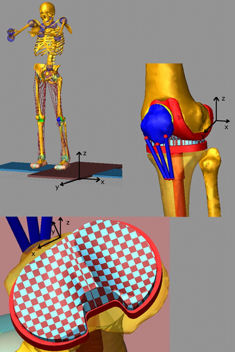
The subject's weight, height, gender, and age as well as the relative positions of the ankle, knee, and hip joints determined from the bone geometries were used to scale a generic model based on the GeBOD anthropometric database library in LifeMOD [25]. The motion markers from a static trial with feet pointed forward were used to pose the generic model. The generic geometries for the pelvis, femur, patella, tibia, and fibula were then replaced with the subject specific ones and the prosthetic components were added to the model by rigidly attaching them to the upper and lower leg segments (Fig. 1). The model included three ligament bundles for the lateral collateral ligament (LCL), three bundles for the medial collateral ligament (MCL), and one bundle for the posterior cruciate ligament (PCL). The ligament bundles were modeled as single force elements. Nonlinear splines were used to define the force–displacement relation for each ligament bundle, including the nonlinear “toe” region. The force–displacement relationship for each bundle is described by [7,26]
| (1) |
| (2) |
Fig. 1.
Full body multibody model with artificial left knee and discretized tibia insert
where is a stiffness parameter, is a spring parameter assumed to be 0.03, is the engineering strain of each ligament bundle, is the ligament length, and is the zero-load length. The values used for were 2000 N for all the bundles of the LCL, 2750 N for all the bundles of the MCL, and 9000 N for the single bundle of the PCL. The zero-load lengths for the ligaments were estimated based on the studies provided by Blankevoort et al. [7] and DeFrate et al. [27] and their insertion/origin positions were derived from previous work in our laboratory [28–30]. The ligament single force elements also included a parallel damper with a damping coefficient of 1 Ns/mm.
The prosthetic tibial tray geometry was divided into medial and lateral sections using a custom macro in ADAMS. The tray geometries were segmented into multiple hexahedral rigid bodies [28]. Each hexahedral element had a 3 × 3 mm cross-sectional area in the transverse plane of the tibia plateau that resulted in 168 elements for the medial side and 158 elements for the lateral side for a total of 326 elements. The custom macro also connected each tibial tray element to the lower leg segment with a fixed joint at the center of the element and defined a deformable contact constraint between each element and the femoral component. The deformable contact model with viscous damping [31] is defined as
| (3) |
where is the contact force, is the interpenetration of the geometries, is a spring constant, and is a damping coefficient. The damping coefficient is defined as follows:
| (4) |
where is the penetration at which the maximum damping value is applied.
Elastic foundation theory [7,15,28] was used to estimate the contact parameters. For small deformations as one would expect in artificial knees the following equation is used:
| (5) |
where E is Young's modulus for the elastic layer, is Poisson's ratio of the layer, h is the layer thickness, and d is the spring deformation. The contact pressure p was computed for values of E = 463 MPa, = 0.46, h = 3 mm with d as an unknown spring deformation. Since the tibial component was discretized in 3 × 3 mm elements the value of p/d was then multiplied by 9 mm2 to estimate spring constant of = 6400 N/mm. Values of = 0.1, exponent = 1, and maximum damping coefficient = 60 Ns/mm were used in Eqs. (3) and (4). Equations (3) and (4) were also used to define the contact between the patellar component and the femur with values of = 30,000 N/mm, = 0.1, exponent = 1.5, and maximum damping coefficient = 40 Ns/mm [32]. Friction was included in this contact with a static coefficient of 0.03 and a dynamic coefficient of 0.01, stiction transition velocity of 100 mm/s and friction transition velocity of 1000 mm/s.
Triaxial hinge joints with passive torsional spring-dampers were used to model the hip, ankle, and the joints of the upper body. Foot-floor interaction was modeled with eleven ellipsoids representing each foot. The deformable contact model of Eq. (3) was employed with parameters = 87 N/mm, = 0.1, = 20 Ns/mm, and = 3 between the foot ellipsoids and the force plates geometries. The bone geometries were used to define the metatarsophalangeal joint as a hinge joint in each foot. Forty-five muscle elements were added to each leg and the attachments of the quadriceps muscles of the left leg were modified to insert on the patella. Muscle elements act as passive recording elements during inverse dynamics and as linear actuators during forward dynamics. Motion constraints from the experimentally measured kinematics were then attached to the model and used to place the model in the initial position.
The measured kinematics were used to move the model as constrained by the joints, prosthetic contacts, ligaments, and foot-ground contacts. The shortening/lengthening patterns of each muscle through its via points were recorded during this inverse dynamics step. The joint motion of the upper body was also recorded. Next the motion constraints were removed and the muscle elements served as actuators for the muscle driven forward simulation. The force magnitude of each muscle element was determined by a feedback controller that used the error between the current muscle length in the forward simulation and the muscle length recorded during the inverse dynamics step. The force generated by each muscle was limited by its force generating capacity defined by the following equation:
| (6) |
where is the maximum force allowed for each muscle, PCSA is the physiological cross-sectional area of the muscle as determined from the LifeMOD database library [25], and = 1.7 N/mm2 is the maximum muscle stress [33–35]. The proportional-integral-derivative feedback controller (PID) used to calculate the muscle forces during the forward simulation used the muscle length history recorded in the inverse dynamics step as the target to generate the required force. To account for muscle size, a reference value of PCSA = 1500 mm2 was used to scale the gains of the PID controller. Muscles with PCSA larger than the reference value, therefore, had higher gains than the muscles with PCSA values less than the reference. To compensate for small numerical errors during the forward simulation, a tracking agent was used in LifeMod. This tracking agent is a six-axis spring located between the pelvis and a “dummy” rigid body. The dummy rigid body follows a motion constraint measured during the inverse dynamics step. The vertical direction is free of constraints such that the tracking agent does not impose any forces in the vertical direction. The overall influence of this tracking agent was minimal on the forward model. In particular, for the squat motion simulation the average forces on the tracking agent was 17.6 N along the frontal plane and 14.7 N along the sagittal plane, and for the toe-rise motion the average forces were 24.6 N and 2.2 N for the frontal and sagittal planes, respectively. The upper body motion was also controlled by feedback controllers imposed on the triaxial joints of the upper body. The controller produces the required torque to reproduce the joint motions measured during the inverse dynamics step.
The same procedures were used for both the squat and toe-rise motions. The model was validated by comparing the predicted tibia component forces to the eTibia measurements, predicted ground reaction forces to the experimental measurements from the force plates and comparing the predicted muscle activations to the experimental EMG measurements. The experimental EMG measurements were linearly enveloped using a second order Butterworth low-pass filter with a cutoff frequency of 15 Hz. Initial and final-time artifacts were minimized by using forward and backward reflection of the data [36] and phase shift was eliminated by using forward and backward passes [37]. The EMG signals were then normalized to the MVC data provided for each muscle. The kinematics from the inverse dynamics simulations were also compared to the kinematics from the forward dynamics simulations to verify that the kinematics were replicated correctly. For the tibial component force and moments, the ground reaction forces and the kinematics, the root mean squared deviation (RMSD) and the mean absolute deviation (MAD) from the experimental measures were computed using the following:
| (7) |
| (8) |
where m is the model value and d is an experimental value at each time point i, and k is the number of points.
Results
Squat Model.
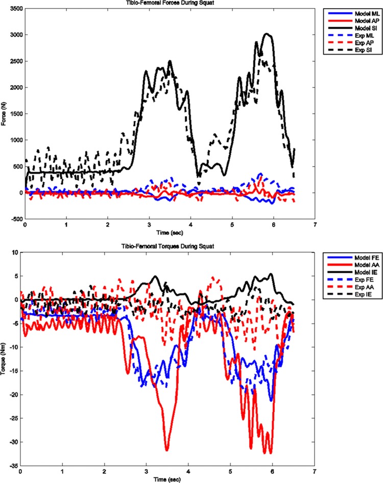
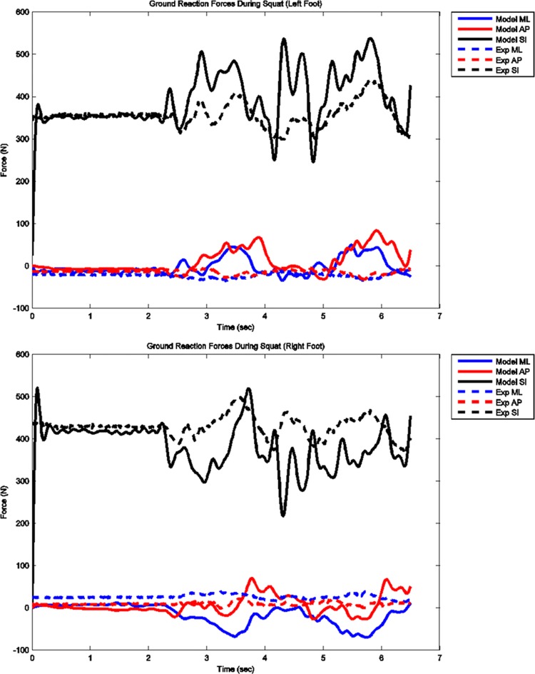
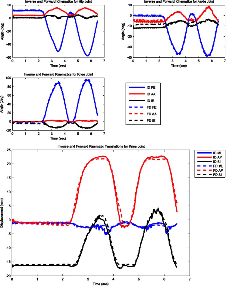
The model predicted forces and torques on the tibial component and the ground reaction forces along with the experimental measurements from the instrumented prosthesis and the force plates are presented in Figs. 2 and 3. The MAD and RMSD values for all validation measures are presented in Table 1. Knee forces and translations are reported in the medial-lateral direction (ML), the anterior-posterior (AP) direction, and superior-inferior (SI) direction. Joint rotations and torques are broken into flexion-extension (FE), adduction-abduction (AA), and internal-external (IE) components. The muscle driven forward dynamics model for the squat motion replicates the segment kinematics very accurately as can been seen in Fig. 4. The EMG recordings from the squat trial demonstrated that the muscles most active during this motion were the medial and lateral gastrocnemius, the peroneus longus, the rectus femoris, the vastus lateralis, and the vastus medialis; therefore, the muscle activation patterns computed during the forward simulation for those muscles were compared to the experimental measurements (Fig. 5). The discretized tibial component used in this model allows for an evaluation of the contact pressures on the prosthetic component and the locations of these contacts. The contact pressure maps for the tibial component during one cycle of squat motion are shown in Fig. 6. The contact area moves anteriorly during knee flexion in both the medial and lateral sides and then moves posteriorly to its initial position during knee extension. Maximum contact pressure occurs in the lateral side of the tibial component.
Fig. 2.
Model predicted and measured tibial component forces and torques during squat motion
Fig. 3.
Model predicted and measured ground reaction forces for left and right feet during squat motion
Table 1.
Mean absolute deviation and root mean squared deviations for all outcomes used to validate models. Translational directions correspond to the medial-lateral (ML), anterior-posterior (AP), and superior-inferior (SI) directions. Rotational directions are reported in terms of flexion-extension (FE), adduction-abduction (AA), and internal-external (IE) rotations. Translations of the knee joint are measured as the tibial translation with respect to the femur.
|
|
Squat |
Toe-rise |
|||
|---|---|---|---|---|---|
| MAD | RMSD | MAD | RMSD | ||
| eTibia Forces | ML (N) | 76 | 92 | 46 | 57 |
| AP (N) | 69 | 90 | 63 | 77 | |
| SI (N) | 279 | 345 | 325 | 416 | |
| eTibia Torques | FE (Nm) | 2.109 | 2.869 | 7.485 | 8.409 |
| AA (Nm) | 8.737 | 11.548 | 21.026 | 25.257 | |
| IE (Nm) | 1.889 | 2.406 | 2.114 | 2.507 | |
| GRF Left | ML (N) | 23 | 32 | 6 | 9 |
| AP (N) | 27 | 40 | 17 | 21 | |
| SI (N) | 45 | 67 | 94 | 109 | |
| GRF Right | ML (N) | 43 | 51 | 26 | 34 |
| AP (N) | 18 | 22 | 31 | 36 | |
| SI (N) | 53 | 72 | 82 | 99 | |
| Kinematics | Hip FE (deg) | 0.5 | 0.6 | 1.2 | 1.3 |
| Hip AA (deg) | 0.2 | 0.2 | 1.2 | 1.3 | |
| Hip IE (deg) | 0.7 | 0.8 | 0.6 | 0.7 | |
| Ankle FE (deg) | 0.9 | 0.9 | 1.3 | 1.4 | |
| Ankle AA (deg) | 0.8 | 1.0 | 1.2 | 1.2 | |
| Ankle IE (deg) | 1.8 | 2.3 | 4.2 | 4.6 | |
| Knee FE (deg) | 2.6 | 2.8 | 7.5 | 8.0 | |
| Knee AA (deg) | 0.5 | 0.7 | 0.3 | 0.5 | |
| Knee IE (deg) | 2.1 | 2.6 | 0.8 | 1.0 | |
| Knee ML (mm) | 0.5 | 0.7 | 0.3 | 0.3 | |
| Knee AP (mm) | 0.7 | 1.0 | 1.1 | 1.3 | |
| Knee SI (mm) | 0.6 | 0.7 | 1.0 | 1.1 | |
Fig. 4.
Computed joint kinematics during muscle driven simulation (FD) versus inverse dynamics simulation (ID) during squat motion
Fig. 5.
Model predicted muscle activations versus measured normalized EMG for the primary muscles involved in squat motion
Fig. 6.
Contact pressure (N/mm2) distribution on tibia component during one cycle of squat motion
Toe-Rise Model.
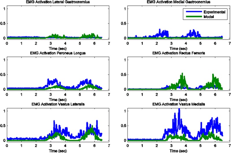
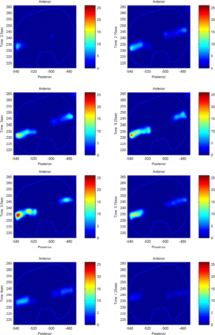
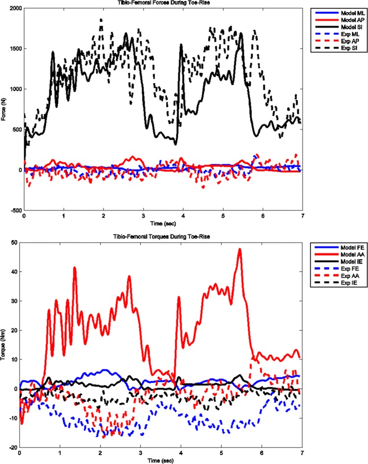
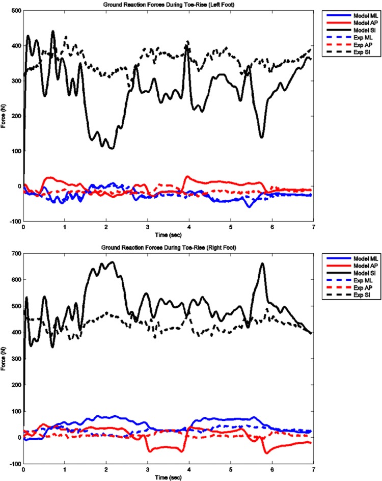
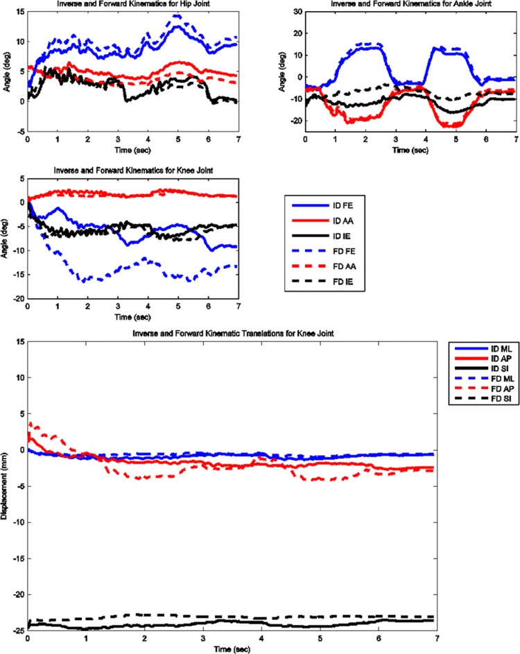
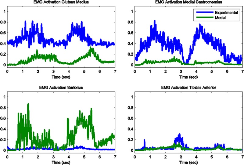
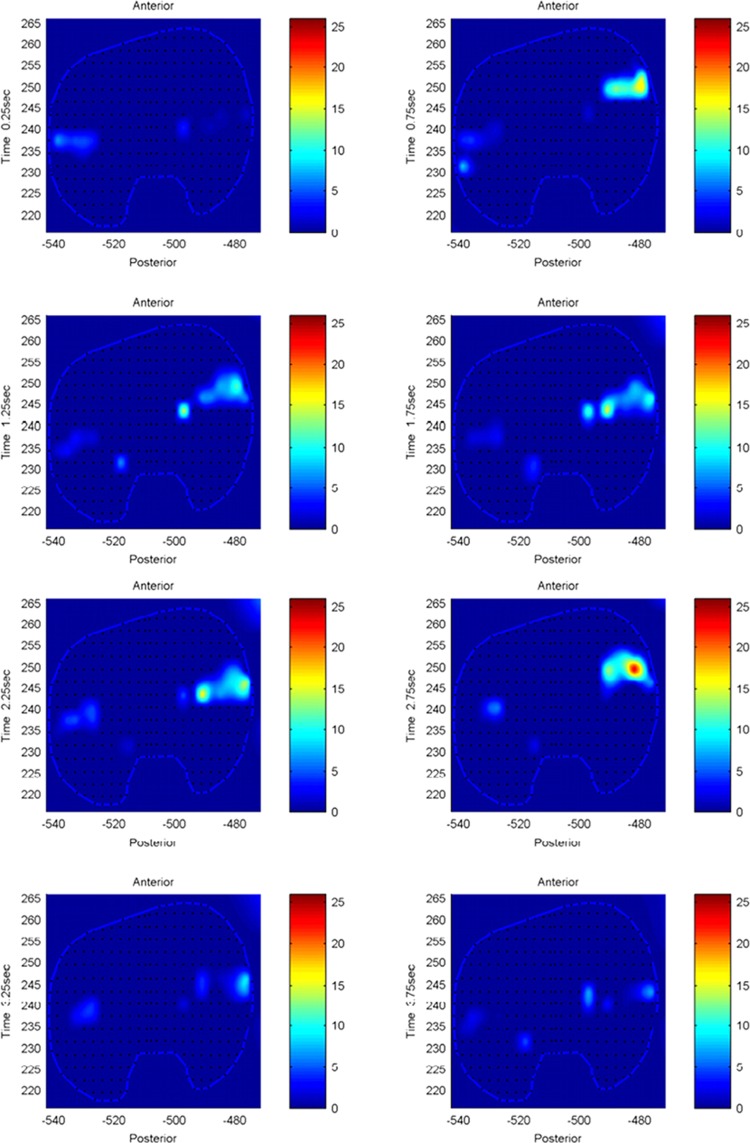
The model predicted forces and torques on the tibial component and the ground reaction forces along with the experimental measurements from the instrumented prosthesis and the force plates are presented in Figs. 7 and 8. The muscle driven forward dynamics model for the toe-rise motion replicates the segment kinematics accurately as can been seen in Fig. 9. In the case of the toe-rise motion the most active muscles were the gluteus medius, the medial gastrocnemius, the sartorius, and the tibialis anterior. Comparison of the computed muscle activation patterns of these muscles to the EMG records is shown in Fig. 10. The contact pressure maps for the tibial component during one cycle of toe-rise motion are shown in Fig. 11. The contact area moves slightly anteriorly during the rising phase of the motion and then moves back to its starting position during the downward phase. The maximum in this case occurs in the medial-anterior area of the tibial component.
Fig. 7.
Model predicted and measured tibial component forces and torques during toe-rise motion
Fig. 8.
Model predicted and measured ground reaction forces for left and right feet during toe-rise motion
Fig. 9.
Computed joint kinematics during muscle driven simulation (FD) versus inverse dynamics simulation (ID) during toe-rise motion
Fig. 10.
Model predicted muscle activations versus measured normalized EMG for the primary muscles involved in toe-rise motion
Fig. 11.
Contact pressure (N/mm2) distribution on tibia component during one cycle of toe-rise motion
Discussion
Many studies have recognized the need for dynamic models that link motion, muscle forces, and joint contacts. This study presents a methodology for body-level forward dynamics simulation with patient specific geometries that fulfills this need. The model used in this study predicted muscle and contact forces concurrently during squat and toe-rise motion. This was achieved by creating a full body dynamic skeletal model with patient specific bone and artificial knee component geometries that included muscle, ligament, and articular contact models. Moreover the tibial insert was discretized into multiple hexahedral elements that facilitate the computation of contact forces and location of the contact areas. An important obstacle in using computational models to address clinically relevant questions is the validation of the model. In most studies model predictions are validated by comparing the predicted time histories of the muscle forces and ground reaction forces against experimental measurements obtained from surface EMG and force plates. Muscle forces are one of the major contributors to contact loading at the joints [38], which implies that in order to correctly predict tibiofemoral contact forces, the muscle force and pattern predictions need to be accurate. Since the knee joint is spanned by many muscles the net joint torque and joint kinematics can be produced by multiple combinations of muscle activations [17]. The 2012 Grand Challenge Data sets [1], provide a unique opportunity to the modeling community to validate the methods and parameters used in models that attempt to predict in vivo loading at the knee joint. Because the joint loading can be directly compared to the measurements from the instrumented implant we can be confident that accurate joint contact predictions are the result of reasonable muscle force predictions.
The purpose of this study was to create a full body muscle driven simulation with patient specific lower limb geometries and validate the model in terms of kinematics, EMG patterns, and ground reaction forces. The instrumented knee prosthesis was used to validate the predicted in vivo loading on the tibial component. The current model uses CT derived geometries for the lower extremities and the knee replacement components. A contact model based on elastic foundation theory is used to model the interaction of the tibial and femoral components as well as the contact between the patella and femoral components. Single force elements were implemented to model the ligament bundles for the collateral and posterior cruciate ligaments. Forty-five muscle elements were incorporated in each leg and a PID controller was used to compute muscle activations. In addition the model featured a discretized tibial component that allowed computation of the contact pressure and contact area on the prosthetic component.
The mean absolute deviation (MAD) value for the vertical contact force on the tibial component during the squat was 279 N and for the toe-rise motion was 325 N. This means that on average the prediction of the in vivo compressive force on the tibial component during the squat motion was within 279 N of the measured value and in the case of the toe-rise within 325 N of the measured value. Due to the noisy nature of the measured signal from the instrumented prosthesis, it is not possible to compute an accurate estimate for the goodness of fit between predicted and measured values but when the MAD and RMSD values are taken in conjunction with the plots of the results, it appears that the tibiofemoral force predictions are reasonably accurate. The same arguments can be made for the comparisons of the predicted ground reaction forces to the force plate data. The MAD values for the vertical component of the force during squat motion for left and right foot are only 45 and 53 N, respectively, and 94 and 82 N for the toe-rise motion. These correspond to deviations in the order of 10% of subject's body weight. Although the predicted ground reaction forces compare favorably to the force plate data in terms of RMSD and MAD values, the loading patterns are somewhat different especially in the toe-rise condition (Figs. 3 and 8). These differences may be explained by the fact that the feet are modeled as two rigid bodies connected by a single metatarsophalangeal joint and the foot-floor interaction is modeled with 11 ellipsoids representing each foot. The absence of the phalangeal articulations can significantly affect the floor contact force distribution particularly in the toe-rise motion. Moreover, the ellipsoids used to represent the foot can have a significant effect on the distribution of the contact force with the ground that, in turn, can affect the torques at the ankle and knee joint.
The greatest deviations from the experimental measures occurred for the toe-rise motion and in particular for the torque around the AP axis (abduction–adduction torque). The abduction–adduction torque errors are possibly caused by slight misalignment of the knee relative to the hip and ankle joints, inaccurate muscle moment arms due to inaccurate muscle origin and attachment points, errors in the calculation of the ground reaction forces particularly in the medial-lateral direction, and inaccuracies in the prediction of the muscle activations.
The model kinematics in the muscle driven forward simulation are in good agreement with the motion data. The greatest deviation in terms of kinematic parameters between the forward muscle driven simulation and the inverse dynamics occurs for the left knee flexion-extension angle during the toe-rise as seen in Fig. 9 and may be indicative of inaccurate muscle moment arms due to inaccurate muscle origin and attachment points of the quadriceps muscles. Inaccuracies in muscle attachment points or joint axis locations are a common problem in musculoskeletal modeling [1].
The knee joint forces observed in this study concur to the ones reported by Mundermann et al. [2] for the case of squat motion; however, in their study the maximum compressive forces were observed in the medial compartment whereas in this study the maximum contact pressures were observed in the lateral compartment. A possible reason for this discrepancy is the inaccurate prediction of the abduction-adduction torque, which would affect the medial to lateral load rotation. Even so, direct comparison of the medial to lateral load ratio between studies can be tricky as Mundermann et al. [2] point out the ratio can be affected by soft tissue status, surgical technique, and the way that the activity was performed. The range of RMS error in knee joint loading for both conditions is very similar to the ones reported by Kim et al. [17] during gait using a similar instrumented total knee replacement.
Most multibody musculoskeletal models compute the knee joint contact forces as single contacts in the medial and lateral compartments [15,17,39]. In our study the tibial component was discretized in 3 × 3 mm hexahedral elements and a deformable contact between each element and the femoral component was defined. The medial and lateral compartment contact forces are, therefore, resolved in multiple components with a spatial resolution of 3 mm. This spatial resolution is an important feature in identifying the contact patches on the tibial component. For example, in the current study, by observing the contact force magnitudes and contact patches we can identify several differences on the joint loading pattern between the squat and toe-rise motions. In the case of the squat motion the contact forces are higher in the lateral compartment whereas during the toe-rise motion the contact forces are higher in the medial compartment with the maximum occurring in the anterior side of the medial compartment (Figs. 6 and 11). In this study only the magnitude of each contact force on every hexahedral element was considered in the comparison to the instrumented artificial knee measurements, however, the contact force in each element can be resolved into its three spatial components and a map of the shearing forces can also be constructed. The aforementioned improvements in contact force predictions can be extremely useful in incorporating a finite element model in conjunction with the multibody model to compute stress distributions at specific time frames. In our current model the average thickness of the tibial component (h = 3 mm) was used in Eq. (5) but the model can be further refined by employing a varying thickness in the deformable contact definition for each element.
Our study has a number of insufficiencies concerning the data that warrant further consideration. Previous published work with cadaver specimens [28–30] was used to determine the ligament locations. In particular the cadaver derived geometries were linearly scaled to match the CT derived geometries of the subject in the current study and the ligament locations were extracted from the scaled cadaver specimens. The zero-load lengths for the ligaments were then determined by scaling data found in the literature [7,27]. A better approach would be to derive these values directly from the subject by means of magnetic resonance imaging and knee laxity tests since it has been shown that zero-load lengths can have a significant impact on knee kinematics [40]. The errors between the predicted and measured ground reaction forces are possibly caused by the same misalignments of the knee relative to the hip and ankle joints. Another contributing factor is that CT derived geometries were only available for the left side, which included the total knee replacement. In our model the right leg geometries were created by mirroring the left leg geometries. The right knee joint was a natural joint and different motion profiles would be expected. This was done in order to avoid large asymmetries between the left and right side seen when one knee is modeled anatomically and the other is modeled as a simple hinge [41]. It was preferable to use the mirrored geometries with a prosthetic knee on the right side than simplified geometries with a hinge joint to model the native knee. Ironically, forcing this symmetry on the model of an asymmetrical individual may have contributed to some of the errors in the ML ground reaction forces that in turn would contribute to the discrepancies in AA torques at the knee joint.
The predicted muscle activations for both models are computed in the forward simulation by using the lengthening pattern of each muscle as recorded in the inverse dynamics step. This method is extremely fast but the drawback is that real muscles can be active without a change in the length, in which case the force estimate for that muscle is not accurate. The activation patterns of the major contributing muscles for each of the two motion conditions were correctly identified and compared favorably to the recorded EMG trails. Lloyd et al. [42] demonstrated that wrong muscle force predictions for larger muscles can lead to incorrect joint moment estimations while the contribution of smaller muscles remains negligible. The knee joint loading and muscle force relationship is not one-to-one but the accurate prediction of the in vivo loading at the knee joint and the consistency of the predicted muscle force patterns compared to the muscle activity obtained from EMG (Figs. 5 and 10) give confidence to our results. Moreover, the joint kinematics computed in the muscle driven forward simulation replicated the joint motions from the inverse dynamics step which further strengthens the argument that the muscle contributions to joint loading are reasonable.
Ongoing work in our lab has shown that contact parameters and geometries of the foot affect the contact pressure distributions as well as the moments at the knee joint. In the current model the foot-floor contact was modeled using generic ellipsoid geometries. Future work will concentrate on more accurate modeling of the foot and/or footwear geometries and refinement of contact parameters. Another area of improvement and refinement is in the muscle activation solution. Currently all muscle forces are computed in a closed loop PID control scheme. The possibility of incorporating a hybrid controller in which some muscles are driven by the experimental data in a feed-forward fashion while the rest are still in closed loop control will be explored.
In conclusion, the detailed dynamic model and methodology presented in this study provides a useful and versatile tool in studying the knee joint loading during motion. Bridging the gap between simulation and clinical applications requires validation of the computational models and improvements in the accuracy of predicted in vivo loads. The model used in this study proved capable of accurately predicting the in vivo loads at the knee joint when compared to the measurements obtained from the instrumented knee prosthesis. In addition the muscle and ligament forces were computed concurrently and significant improvements were made in predicting the spatial distribution of the contact loads. Detailed subject specific data can further improve the accuracy of the model and the validity of this methodology in other dynamic motions, such as gait, chair rise, running, etc., needs to be established.
Contributor Information
Antonis P. Stylianou, Research Associate, e-mail: stylianoua@umkc.edu .
Trent M. Guess, Associate Professor, e-mail: guesstr@umkc.edu
Mohammad Kia, Research Associate, e-mail: kiam@umkc.edu, Department of Civil & Mechanical Engineering, Musculoskeletal Biomechanics Research Lab, University of Missouri—Kansas City, 350K Robert H Flarsheim Hall, 5110 Rockhill Rd., Kansas City, MO 64110.
References
- [1]. Fregly, B. J. , Besier, T. F. , Lloyd, D. G. , Delp, S. L. , Banks, S. A. , Pandy, M. G. , and D'Lima, D. D. , 2012, “Grand challenge competition to predict in vivo knee loads,” J. Orthop. Res., 30(4), pp. 503–513. 10.1002/jor.22023 [DOI] [PMC free article] [PubMed] [Google Scholar]
- [2]. Mundermann, A. , Dyrby, C. O. , D'Lima, D. D. , Colwell, C. W., Jr ., and Andriacchi, T. P. , 2008, “In vivo knee loading characteristics during activities of daily living as measured by an instrumented total knee replacement,” J. Orthop. Res., 26(9), pp. 1167–1172. 10.1002/jor.20655 [DOI] [PubMed] [Google Scholar]
- [3]. Heinlein, B. , Kutzner, I. , Graichen, F. , Bender, A. , Rohlmann, A. , Halder, A. M. , Beier, A. , and Bergmann, G. , 2009, “ESB Clinical Biomechanics Award 2008: Complete data of total knee replacement loading for level walking and stair climbing measured in vivo with a follow-up of 6-10 months,” Clin. Biomech. (Bristol, Avon), 24(4), pp. 315–326. 10.1016/j.clinbiomech.2009.01.011 [DOI] [PubMed] [Google Scholar]
- [4]. Andriacchi, T. P. , Mundermann, A. , Smith, R. L. , Alexander, E. J. , Dyrby, C. O. , and Koo, S. , 2004, “A framework for the in vivo pathomechanics of osteoarthritis at the knee,” Ann. Biomed. Eng., 32(3), pp. 447–457. 10.1023/B:ABME.0000017541.82498.37 [DOI] [PubMed] [Google Scholar]
- [5]. Wimmer, M. A. , and Andriacchi, T. P. , 1997, “Tractive forces during rolling motion of the knee: implications for wear in total knee replacement,” J. Biomech., 30(2), pp. 131–137. 10.1016/S0021-9290(96)00112-1 [DOI] [PubMed] [Google Scholar]
- [6]. Sathasivam, S. , and Walker, P. S. , 1998, “Computer model to predict subsurface damage in tibial inserts of total knees,” J. Orthop. Res., 16(5), pp. 564–571. 10.1002/jor.1100160507 [DOI] [PubMed] [Google Scholar]
- [7]. Blankevoort, L. , Kuiper, J. H. , Huiskes, R. , and Grootenboer, H. J. , 1991, “Articular contact in a three-dimensional model of the knee,” J. Biomech., 24(11), pp. 1019–1031. 10.1016/0021-9290(91)90019-J [DOI] [PubMed] [Google Scholar]
- [8]. Pandy, M. G. , Sasaki, K. , and Kim, S. , 1998, “A Three-Dimensional Musculoskeletal Model of the Human Knee Joint. Part 1: Theoretical Construct,” Comput. Methods Biomech. Biomed. Engin., 1(2), pp. 87–108. 10.1080/01495739708936697 [DOI] [PubMed] [Google Scholar]
- [9]. Abdel-Rahman, E. M. , and Hefzy, M. S. , 1998, “Three-dimensional dynamic behaviour of the human knee joint under impact loading,” Med. Eng. Phys., 20(4), pp. 276–290. 10.1016/S1350-4533(98)00010-1 [DOI] [PubMed] [Google Scholar]
- [10]. Cohen, Z. A. , Roglic, H. , Grelsamer, R. P. , Henry, J. H. , Levine, W. N. , Mow, V. C. , and Ateshian, G. A. , 2001, “Patellofemoral stresses during open and closed kinetic chain exercises. An analysis using computer simulation,” Am. J. Sports Med., 29(4), pp. 480–487. [DOI] [PubMed] [Google Scholar]
- [11]. Dhaher, Y. Y. , and Kahn, L. E. , 2002, “The effect of vastus medialis forces on patello-femoral contact: a model-based study,” J. Biomech. Eng., 124(6), pp. 758–767. 10.1115/1.1516196 [DOI] [PubMed] [Google Scholar]
- [12]. Chao, E. Y. , 2003, “Graphic-based musculoskeletal model for biomechanical analyses and animation,” Med. Eng. Phys., 25(3), pp. 201–212. 10.1016/S1350-4533(02)00181-9 [DOI] [PubMed] [Google Scholar]
- [13]. Elias, J. J. , Wilson, D. R. , Adamson, R. , and Cosgarea, A. J. , 2004, “Evaluation of a computational model used to predict the patellofemoral contact pressure distribution,” J. Biomech., 37(3), pp. 295–302. 10.1016/S0021-9290(03)00306-3 [DOI] [PubMed] [Google Scholar]
- [14]. Piazza, S. J. , and Delp, S. L. , 2001, “Three-dimensional dynamic simulation of total knee replacement motion during a step-up task,” J. Biomech. Eng., 123(6), pp. 599–606. 10.1115/1.1406950 [DOI] [PubMed] [Google Scholar]
- [15]. Bei, Y. , and Fregly, B. J. , 2004, “Multibody dynamic simulation of knee contact mechanics,” Med. Eng. Phys., 26(9), pp. 777–789. 10.1016/j.medengphy.2004.07.004 [DOI] [PMC free article] [PubMed] [Google Scholar]
- [16]. Halloran, J. P. , Petrella, A. J. , and Rullkoetter, P. J. , 2005, “Explicit finite element modeling of total knee replacement mechanics,” J. Biomech., 38(2), pp. 323–331. 10.1016/j.jbiomech.2004.02.046 [DOI] [PubMed] [Google Scholar]
- [17]. Kim, H. J. , Fernandez, J. W. , Akbarshahi, M. , Walter, J. P. , Fregly, B. J. , and Pandy, M. G. , 2009, “Evaluation of predicted knee-joint muscle forces during gait using an instrumented knee implant,” J. Orthop. Res., 27(10), pp. 1326–1331. 10.1002/jor.20876 [DOI] [PubMed] [Google Scholar]
- [18]. Lundberg, H. J. , Foucher, K. C. , Andriacchi, T. P. , and Wimmer, M. A. , 2012, “Direct comparison of measured and calculated total knee replacement force envelopes during walking in the presence of normal and abnormal gait patterns,” J. Biomech., 45(6), pp. 990–996. 10.1016/j.jbiomech.2012.01.015 [DOI] [PMC free article] [PubMed] [Google Scholar]
- [19]. Lundberg, H. J. , Foucher, K. C. , and Wimmer, M. A. , 2009, “A parametric approach to numerical modeling of TKR contact forces,” J. Biomech., 42(4), pp. 541–545. 10.1016/j.jbiomech.2008.11.030 [DOI] [PMC free article] [PubMed] [Google Scholar]
- [20]. Godest, A. C. , Beaugonin, M. , Haug, E. , Taylor, M. , and Gregson, P. J. , 2002, “Simulation of a knee joint replacement during a gait cycle using explicit finite element analysis,” J. Biomech., 35(2), pp. 267–275. 10.1016/S0021-9290(01)00179-8 [DOI] [PubMed] [Google Scholar]
- [21]. Baldwin, M. A. , Clary, C. W. , Fitzpatrick, C. K. , Deacy, J. S. , Maletsky, L. P. , and Rullkoetter, P. J. , 2012, “Dynamic finite element knee simulation for evaluation of knee replacement mechanics,” J. Biomech., 45(3), pp. 474–483. 10.1016/j.jbiomech.2011.11.052 [DOI] [PubMed] [Google Scholar]
- [22]. Lanovaz, J. L. , and Ellis, R. E. , 2009, “A cadaverically evaluated dynamic FEM model of closed-chain TKR mechanics,” J. Biomech. Eng., 131(5), p. 051002. 10.1115/1.3078159 [DOI] [PubMed] [Google Scholar]
- [23]. Zelle, J. , Heesterbeek, P. J. , Waal Malefijt De, M., and Verdonschot , N., 2010, “Numerical analysis of variations in posterior cruciate ligament properties and balancing techniques on total knee arthroplasty loading,” Med. Eng. Phys., 32(7), pp. 700–707. 10.1016/j.medengphy.2010.04.013 [DOI] [PubMed] [Google Scholar]
- [24]. Fregly, B. J. , Bei, Y. , and Sylvester, M. E. , 2003, “Experimental evaluation of an elastic foundation model to predict contact pressures in knee replacements,” J. Biomech., 36(11), pp. 1659–1668. 10.1016/S0021-9290(03)00176-3 [DOI] [PubMed] [Google Scholar]
- [25]. Lifemodeler, I. , 2010, “Lifemod Manual.”, Lifemodeler Inc., San Clemente, CA. [Google Scholar]
- [26]. Wismans, J. , Veldpaus, F. , Janssen, J. , Huson, A. , and Struben, P. , 1980, “A three-dimensional mathematical model of the knee-joint,” J. Biomech., 13(8), pp. 677–685. 10.1016/0021-9290(80)90354-1 [DOI] [PubMed] [Google Scholar]
- [27]. DeFrate, L. E. , Gill, T. J. , and Li, G. , 2004, “In vivo function of the posterior cruciate ligament during weightbearing knee flexion,” Am. J. Sports Med., 32(8), pp. 1923–1928. 10.1177/0363546504264896 [DOI] [PubMed] [Google Scholar]
- [28]. Guess, T. M. , Liu, H. , Bhashyam, S. , and Thiagarajan, G. , 2013, “A multibody knee model with discrete cartilage prediction of tibio-femoral contact mechanics,” Comput. Meth. Biomech. Biomed. Eng., 16(3), pp. 256–270. 10.1080/10255842.2011.617004 [DOI] [PubMed] [Google Scholar]
- [29]. Guess, T. M. , Thiagarajan, G. , Kia, M. , and Mishra, M. , 2010, “A subject specific multibody model of the knee with menisci,” Med. Eng. Phys., 32(5), pp. 505–515. 10.1016/j.medengphy.2010.02.020 [DOI] [PubMed] [Google Scholar]
- [30]. Guess, T. M. , and Stylianou, A. , 2012, “Simulation of anterior cruciate ligament deficiency in a musculoskeletal model with anatomical knees,” Open Biomed. Eng. J., 6, pp. 23–32. 10.2174/1874230001206010023 [DOI] [PMC free article] [PubMed] [Google Scholar]
- [31]. Machado, M. , Moreir, P. , Flores, P. , and Lankarani, H. M. , 2012, “Compliant contact force models in multibody dynamics:Evolution of the Hertz contact theory.,” Mechanism and Machine Theory, 53, pp. 99–121. 10.1016/j.mechmachtheory.2012.02.010 [DOI] [Google Scholar]
- [32]. Guess, T. M. , and Maletsky, L. P. , 2005, “Computational modelling of a total knee prosthetic loaded in a dynamic knee simulator,” Med. Eng. Phys., 27(5), pp. 357–367. 10.1016/j.medengphy.2004.11.003 [DOI] [PubMed] [Google Scholar]
- [33]. Li, L. , Tong, K. , Song, R. , and Koo, T. K. , 2007, “Is maximum isometric muscle stress the same among prime elbow flexors?,” Clin. Biomech. (Bristol, Avon), 22(8), pp. 874–883. 10.1016/j.clinbiomech.2007.06.001 [DOI] [PubMed] [Google Scholar]
- [34]. Fukunaga, T. , Roy, R. R. , Shellock, F. G. , Hodgson, J. A. , and Edgerton, V. R. , 1996, “Specific tension of human plantar flexors and dorsiflexors,” J. Appl. Physiol., 80(1), pp. 158–165. [DOI] [PubMed] [Google Scholar]
- [35]. McMahon, T. A. , 1984, Muscles, reflexes, and locomotion, Princeton University Press, Princeton, NJ. [Google Scholar]
- [36]. Smith, G. , 1989, “Padding point extrapolation techniques for the Butterworth digital filter,” J. Biomech., 22(8–9), pp. 967–971. 10.1016/0021-9290(89)90082-1 [DOI] [PubMed] [Google Scholar]
- [37]. Winter, D. A. , 1990, Biomechanics and motor control of human movement, Wiley, New York, NY. [Google Scholar]
- [38]. Shelburne, K. B. , Torry, M. R. , and Pandy, M. G. , 2006, “Contributions of muscles, ligaments, and the ground-reaction force to tibiofemoral joint loading during normal gait,” J. Orthop. Res., 24(10), pp. 1983–1990. 10.1002/jor.20255 [DOI] [PubMed] [Google Scholar]
- [39]. Lin, Y. C. , Walter, J. P. , Banks, S. A. , Pandy, M. G. , and Fregly, B. J. , 2010, “Simultaneous prediction of muscle and contact forces in the knee during gait,” J. Biomech., 43(5), pp. 945–952. 10.1016/j.jbiomech.2009.10.048 [DOI] [PubMed] [Google Scholar]
- [40]. Bloemker, K. H. , Guess, T. M. , Maletsky, L. , and Dodd, K. , 2012, “Computational knee ligament modeling using experimentally determined zero-load lengths,” Open Biomed. Eng. J., 6, pp. 33–41. 10.2174/1874230001206010033 [DOI] [PMC free article] [PubMed] [Google Scholar]
- [41]. Guess, T. M. , 2012, “Forward Dynamics Simulation Using a Natural Knee with Menisci in the Multibody Framework,” Multibody Syst. Dyn., 28, pp. 37–53. 10.1007/s11044-011-9293-4 [DOI] [Google Scholar]
- [42]. Lloyd, D. G. , and Buchanan, T. S. , 2001, “Strategies of muscular support of varus and valgus isometric loads at the human knee,” J. Biomech., 34(10), pp. 1257–1267. 10.1016/S0021-9290(01)00095-1 [DOI] [PubMed] [Google Scholar]


