Short abstract
A tissue's microstructure determines its failure properties at larger length scales, however, the specific relationship between microstructure and macroscopic failure in native and engineered soft tissues (such as capsular ligaments, aortic aneurysms, or vascular grafts) has proven elusive. In this study, variations in the microscale fiber alignment in collagen gel tissue analogs were modeled in order to understand their effects on macroscale damage and failure outcomes. The study employed a multiscale finite-element (FE) model for damage and failure in collagen-based materials. The model relied on microstructural representative volume elements (RVEs) that consisted of stochastically-generated networks of discrete type-I collagen fibers. Fiber alignment was varied within RVEs and between layers of RVEs in a macroscopic FE model of a notched dogbone geometry. The macroscale stretch and the microscale response of fibers for each of the differently aligned cases were compared as the dogbone was uniaxially extended to failure. Networks with greater fiber alignment parallel to the direction of extension failed at smaller strains (with a 6–22% reduction in the Green strain at failure), however, at greater grip forces (a 28–60% increase) than networks with fibers aligned perpendicular to the extension. Alternating layers of crisscrossed network alignments (aligned ±45 deg to the direction of extension) failed at smaller strains but at greater grip forces than those created using one fiber alignment type. In summary, variations in microscale structure via fiber alignment produced different macroscale failure trends. To conclude, these findings may be significant in the realm of tissue engineering and in soft tissue biomechanics.
Keywords: biomechanics, multiscale model, tissue failure, collagen, biomaterials
1. Introduction
The role of fiber architecture in soft tissue failure has been demonstrated by recent experimental [1–3] and computational [4–7] studies. Delineating the specific relationship between the microstructure and macroscopic failure response in tissues, however, has proven to be a major challenge. Issues still remain with microscale fiber kinematics, even in macroscale prefailure mechanics, making a more complex multiscale approach attractive and even necessary for certain problems [8] in spite of the additional computational demands.
Important work has been done in linking variations in microstructure to material failure in nonbiological contexts, such as the work of Wang and Sastry [9] on failure in random fiber networks and that of Zhang et al. [10] on failure in fiber-reinforced plastics, however, there has been a gap in the context of engineered and native tissues [11–14]. As the current knowledge of the microstructural properties of healthy and diseased tissues continues to grow [15–19], improved multiscale mechanical models are needed for tissue damage and failure that can link microstructural variation to differing macroscale failure outcomes.
Towards this end, a multiscale finite element (FE) model of collagen gel mechanics was recently adapted to include the failure of individual fibers within micronetworks [20], with that initial study demonstrating that the model can match experimental results in terms of force-displacement data and average fiber kinematics. The current study explores how changes in the model fiber network alignment led to changes in the macroscopic behavior of the tissue.
2. Methods
2.1. Microscale Model.
The multiscale model used in this study consisted of a macroscale FE continuum material linked to the mechanical response of microscale representative volume element (RVE) networks of discrete collagen fibers (which were allowed to fail when stretched beyond a critical value) situated at each Gauss point within the continuum [21,22]. In the present study, the microstructure of RVE fiber networks was varied by changing their fiber alignment—both the direction and degree of alignment—for a series of fiber failure simulations using a notched dogbone geometry.
Isotropic RVE networks of interconnected collagen fibers were created from the edges of Delaunay tessellations generated from a random set of seed points in a four-unit cube. The network tessellations were generated using a Matlab (Natick, MA) implementation of the Quickhull algorithm [23]. Networks were subsequently clipped to a unit cube to reduce boundary artifacts. Fiber alignment along one axis was generated by linearly scaling the coordinates of isotropic networks along that axis and then clipping to a unit cube. Rotation of the networks was performed by coordinate transformation before clipping to a unit cube. Fibers were interconnected via freely rotating pin-joints at fiber-to-fiber nodes. For all simulations, networks contained a mean of 500–550 fibers, and a unique randomly generated RVE network was used for each element within the model. All Gauss points for a given element used the same micrometer scale RVE network.
The force Ff acting along each discrete fiber within a collagen network is calculated as
| (1) |
where Ef is the fiber small-strain tensile modulus, Af is the fiber cross-sectional area, B is a nonlinearity parameter, and εG is the fiber Green strain (calculated as (λf 2 − 1)/2). The constitutive equation was adapted from the work of Billiar and Sacks on the prefailure mechanics of a collagenous tissue [24] and has been previously used to model a range of tissue analogs [25–27]. Damage was introduced at the fiber scale in the model by diminishing the fiber stiffness to a near-zero value when the fiber stretch had exceeded a critical value. Once a fiber had failed within the model, its modulus was irreversibly set to the near-zero value for the duration of the simulation.
The volume-averaged Cauchy stress σij within each RVE is calculated as
| (2) |
where (using index notation) bc is the set of all RVE boundary fiber cross-links, x is the boundary fiber cross-link coordinate, f is the force acting on the boundary fiber cross-link, σL is the local microscale stress, and V is the RVE volume. As was previously done [22], a scaling term for the microscale stress within the model was used to adjust for variations in the RVE network length while maintaining the correct collagen volume fraction.
The fiber alignment within networks is quantified as
| (3) |
where Ω is the fiber orientation tensor [28,29], L fiber is the length of a single fiber, n is the unit vector along the fiber, and L total, is the total network length. By this measure, a completely isotropic network would have all diagonal components in the Ω orientation tensor comprised of Ω11 = Ω22 = Ω33 = 0.33.
2.2. Macroscale Model.
At the continuum scale, the force balance based on the volume-averaged stress from the RVE deformations at each Gauss point is expressed as [21]
| (4) |
where n is the normal vector to the RVE boundary and u is the displacement of the RVE boundary.
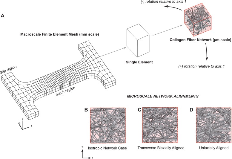
A notched dogbone macroscale FE mesh was used, which consisted of 624 hexahedral elements with trilinear basis functions for a total of 5792 microscale RVE networks (see Fig. 1). The mesh was on the scale of several millimeters (44.0 mm in its longest axis) and was statically gripped at one end and incrementally stretched from the opposing grip to a stretch ratio of 1.5. A notched geometry was chosen based on its previous use in the damage model [20] and its ability to standardize the point of macroscopic failure within the model for each simulation. Mesh convergence was checked against a highly refined mesh with 4992 elements and 39,936 RVEs (eight times the number of original elements, with roughly two times the number of elements in each dimension) for a selected simulation. Several key statistics used in the study remained consistent—the force-displacement area (0.8% absolute difference), the strain at peak force (1.2% absolute difference), stepwise forces (1.8% mean absolute difference), and the peak force (2.4% absolute difference)—with the coarser mesh chosen (to optimize computational time) for this particular study. Mesh symmetry was avoided since unique microscale RVE networks were used in each element of the entire FE domain.
Fig. 1.
(a) Multiscale damage model consisted of a millimeter-scale finite element continuum (in a notched dogbone geometry) with representative volume elements of micrometer-scale collagen fiber networks of varying alignment at each Gauss point. Fibers were allowed to fail when stretched beyond a critical value. The model contained 624 finite elements, with 8 Gauss points per element and with over 500 fibers in each network. The dogbone was fixed at one grip and extended under displacement control from the opposite grip along axis 1 to a final stretch ratio of 1.5. Microscale network fiber alignments were characterized using the orientation tensor Ω and were subsequently rotated relative to the axis of extension. (b) Isotropic networks had initial orientation tensor values of Ω11 = Ω22 = Ω33 = 0.33. (c) Transverse biaxially aligned networks had orientation values of Ω11 = 0.43, Ω22 = 0.13, and Ω33 = 0.43. (d) Uniaxially aligned networks had orientation values of Ω11 = 0.53, Ω22 = 0.23, and Ω33 = 0.23.
2.3. Study Design
2.3.1. Degree and Direction of Alignment in Homogeneous Networks.
Several simulations, varying the microscale fiber alignment and network rotation, were run using the macroscopic notched dogbone stretched to failure along axis 1 (see Fig. 1). Three types of network orientation were considered: isotropic (Ω11 = Ω22 = Ω33 = 0.33), uniaxially aligned (Ω11 = 0.53, Ω22 = 0.23, and Ω33 = 0.23), and transverse biaxially aligned (Ω11 = 0.43, Ω22 = 0.13, and Ω33 = 0.43; the network was transverse isotropic in the 1–3 plane, but was tested in the 1–2 plane). For each of the three cases, the network was also rotated 0 deg, 45 deg, and 90 deg around the 3-axis, producing a total of nine different cases to be analyzed.
2.3.2. Effect of Layering Networks and Merging Networks of Different Alignments.
Two simulations of crisscrossed fibers with composite +45 deg and −45 deg rotated aligned networks were also run for comparison using either: (a) the two-layer macroscale FE mesh with alternating layers (in axis 3) composed of networks rotated +45 deg in one layer and −45 deg in another layer, or (b) merged RVE networks throughout the mesh, which contained two populations of both ±45 deg rotated fibers within each single network (see Fig. 1). Prior to rotation (by either +45 deg or −45 deg relative to the extension axis 1) the mean network orientation tensor values for the networks were Ω11 = 0.6, Ω22 = 0.1, and Ω33 = 0.3. These composite models were then compared to the all +45 deg or all −45 deg rotated network cases for the notched dogbone failure simulation.
For all simulations, similar parameters from a previous study [20] were used: a fiber diameter of 100 nm, a fiber modulus (Ef) of 7.4 MPa, a fiber nonlinearity parameter (B) of 0.25, a collagen density of 1.8 mg/ml, and a fiber stretch failure threshold (λ crit) of 1.42 [26]. The λ crit value in the model was fit, in the previous study, to a series of collagen gel dogbone failure experiments [20] using force-displacement results. Since there were almost 3 × 10⁶ unique fibers modeled in each of the simulations for the present study, a parallel computation strategy at the Minnesota Supercomputing Institute was employed using multiple processors to reduce computation time. Simulations were parallelized using 32 processors with wall times approaching 14–15 h for each simulation case.
3. Results
3.1. Varying Alignment in Homogeneous Networks.
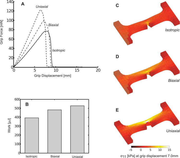
At the macroscale, uniaxially aligned networks produced the greatest grip force prior to failure, followed by biaxially aligned networks, and then by isotropic networks (see Fig. 2(a)). The uniaxially aligned case, however, failed at the smallest grip displacement, followed by the biaxial case, and then by the isotropic case, which failed at the largest grip displacement. Qualitatively, the general trend in the force-displacement response was similar for each case and included a monotonic rise in force, a sharp peak in the force, and then a rapid loss of grip force as the dogbone failed (Fig. 2(a)). At a fixed grip displacement of 7.0 mm, each case (uniaxial, biaxial, and isotropic) generated different macroscopic stress fields (see Figs. 2(c)–2(e)), although, as expected, the stress concentrated at the notch tip in all cases. The force-displacement plot for each case was integrated and the resulting areas (signifying the mechanical work to produce the deformation) were compared (see Fig. 2(b)). The work values followed the trend in peak force, where the uniaxial case generated the largest work and the isotropic case generated the smallest work under the force-displacement curve. However, whereas there was over a 50% difference between the greatest and least peak force values, there was a smaller spread of approximately 25% between the greatest and least work values.
Fig. 2.
(a) Macroscopic grip force varied based on model microscale fiber alignments as dogbone samples were uniaxially stretched to failure. (b) The corresponding mechanical work for these deformations also varied by the alignment case. (c)–(e) At the same grip displacement of 7.0 mm, differences in the stress and deformation for each case were apparent.
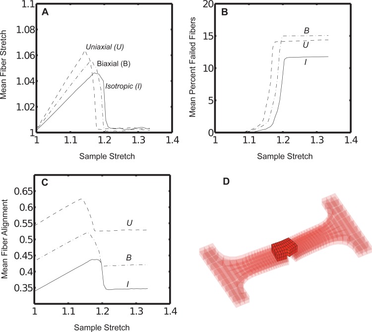
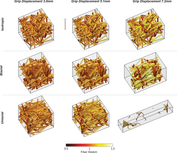
At the microscale, fibers in the uniaxial case experienced the sharpest rise and the largest peak value in mean fiber stretch plotted against the macroscopic dogbone grip-to-grip stretch (see Fig. 3(a)). The isotropic case experienced the smallest mean fiber stretch and the most shallow rise in fiber stretch, with the biaxial case bracketed between the uniaxial and isotropic cases. For this analysis and for all subsequent analyses of the microscale fiber properties in simulations, a subset of notch-adjacent elements was chosen (see Fig. 3(d)) as a sample set. The biaxial case, followed closely by the uniaxial case, experienced the largest loss of fibers over the failure stretch (see Fig. 3(b)). The isotropic case experienced the smallest loss of fibers. Similarly to the fiber stretch, the uniaxial case also experienced the sharpest rise in mean fiber alignment parallel to the axis of extension (measured via Ω11), but peaked at a smaller sample stretch as compared to the biaxial or isotropic cases (see Fig. 3(c)). A single microscale network from the notch-adjacent element set was plotted to visualize differences among the different simulation cases at various grip displacements (see Fig. 4). While the network initially appeared to deform uniformly across simulation type at a small grip displacement (3.0 mm), a displacement near the peak grip force value (7.2 mm) produced quite different outcomes based on network alignment. At 7.2 mm, the uniaxially aligned network had entirely failed (the collagen network no longer percolated across the axis of extension) while the biaxial network was on the verge of failure, and the isotropic network lagged the other two alignment cases in terms of fiber stretch (see Fig. 4). In all cases, RVEs distant from the notch (such as near the dogbone grips) remained largely intact and experienced recoil from the failure of notch-adjacent RVEs. This has also been discussed in a previous study considering failure in different portions of the chosen notched dogbone geometry [20].
Fig. 3.
(a) The mean fiber stretch, (b) the mean percentage of failed fibers, and (c) the mean fiber orientation parameter Ω11 varied over the macroscale sample stretch for each fiber alignment case. (d) Fibers were analyzed from a region of notch-adjacent elements. The same region was used to generate the plots in Figs. 7 and 8.
Fig. 4.
A single microscale network in the model experienced distinct fiber stretches and failure at varying grip displacements for each alignment case. The network was selected from a notch-adjacent element.
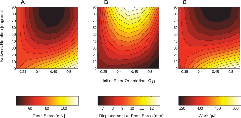
After rotating these three network types (uniaxial, biaxial, and isotropic) by 45 deg and 90 deg, interpolated contour plots of peak force, displacement at peak force, and work (integral of the force-displacement curve) were constructed as functions of the initial fiber orientation and network rotation (see Fig. 5). The largest peak forces generated by the model occurred when fibers were aligned parallel to the direction of the extension. Conversely, the greatest strains at peak force occurred with networks that contained fibers largely oriented perpendicular to the direction of extension. The plot demonstrated that while the initial fiber network helped shape the overall failure response of the dogbone, rotation of the networks produced similar responses for different initial fiber alignments (see Fig. 5).
Fig. 5.
Contour plots of the macroscale (a) peak grip force, (b) displacement at peak grip force, and (c) work were interpolated as functions of the initial network fiber orientation parameter Ω11 and the network rotation. The largest forces occurred when fibers were aligned parallel to extension and the largest prefailure strains when fibers were aligned perpendicular to extension.
3.2. Layering Networks and Merging Networks of Different Alignments.
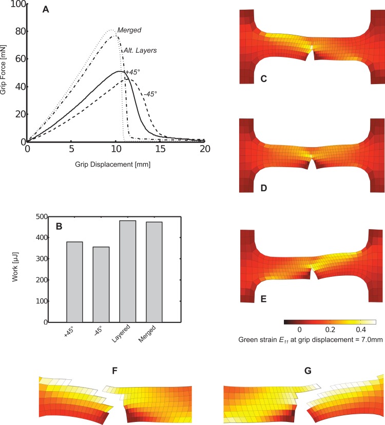
The model produced significantly different macroscale force-displacement responses by using either: (a) all +45 deg or all −45 deg networks, or (b) merged or alternating layers of +45 deg and −45 deg networks (se Fig. 6(a)). Using alternating layers or merged networks produced the largest peak forces, but at the smallest corresponding strains at peak force. Both the homogenous +45 deg and −45 deg cases produced smaller peak forces, but at greater strains. The merged and alternating layer cases resulted in peak forces and strains at peak forces that fell within 5% of one another and followed qualitatively similar force-stretch trajectories. The deformation work (area under the force-displacement curves) also varied relative to the peak force generated in each case, however, as previously seen when comparing alignment, the relative spread in work was less than the spread in peak force values across the simulation cases (see Fig. 6(b)).
Fig. 6.
(a) Macroscopic grip force varied based on differing microscale composite or uniform fiber alignments as dogbone samples were uniaxially stretched to failure. (b) The corresponding mechanical work for these deformations also varied based on the composite or uniform fiber alignment type. (c)–(e) At the same grip displacement of 7.0 mm, differences in the macroscopic Green strain were apparent between the (c) all +45 deg rotated aligned networks, (d) layered ±45 deg networks, and (e) all −45 deg network cases. To illustrate the propagation of failure along the direction of fiber alignment for the (f) all +45 deg and (g) all −45 deg cases, elements with the greatest fiber losses (approximately the top 10%) were removed from plots of notch strains at a grip displacement of 10.8 mm.
The macroscale deformation field also differed among the cases (see Figs. 6(c)–6(e)). In the alternating layer case, the deformation of the dogbone around the notch defect appeared largely symmetric. However, in the +45 deg and −45 deg cases, the deformation of the dogbone was clearly asymmetric around the notch defect. In the +45 deg case, greater element-wise deformation along the axis of extension (based on the E 11 component of the element Green strain) occurred in the region in the (+) axis 1 direction relative to the notch. Conversely, in the −45 deg case, greater deformation fell in the (–) axis 1 direction relative to the notch. Notch failure appeared to propagate in a path roughly parallel to the alignment of the network relative to the direction of extension for the +45 deg and −45 deg off-axis alignments (see Figs. 6(f) and 6(g).
At the microscale, these four cases (+45 deg, all −45 deg, merged, or alternating layers) produced varying trends in the mean fiber stretch, fiber failure, and in the Ω11 fiber orientation parameter (alignment along the axis of extension), as plotted against the macroscale stretch (see Fig. 7). In terms of fiber stretch, the merged and layered cases produced the largest mean fiber stretches and the sharpest rise in fiber stretch and closely followed each other along the entire macroscopic stretch. Both the +45 deg and −45 deg cases lagged behind in terms of stretch magnitude and in the rate of increase in the fiber stretch, but peaked at larger macroscopic stretches prior to failure, as compared to the layered and merged cases (see Fig. 7(a)). The merged and layered cases also showed a steeper rise in fiber loss as compared to the homogeneous cases, but the layered case appeared to lose approximately 20–25% fewer fibers over the stretch (see Fig. 7(b)). The +45 deg and −45 deg cases lost fibers at similar rates over the sample stretch. The greatest microscale differences between the homogeneous (±45 deg networks) and composite cases (layered or merged networks) appeared in comparisons of the change in the Ω11 parameter (see Fig. 7(c)). There was a much more gradual increase in the Ω11 value for the +45 deg or −45 deg cases, as compared to the composite cases, with a smaller peak which occurred at a greater macroscale stretch.
Fig. 7.
(a) The mean fiber stretch, (b) the mean percentage of failed fibers, and (c) the mean fiber orientation parameter Ω11 varied over the macroscale sample stretch for each composite or uniform fiber alignment case. Fibers were analyzed from the notch-adjacent elements depicted in Fig. 3.
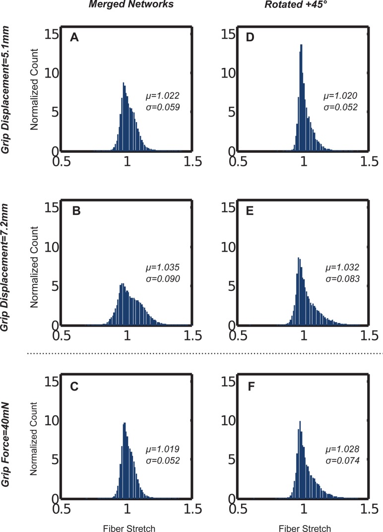
Microscale variation in the fiber stretch distributions for the composite cases was also evident (see Fig. 8). The mean and standard deviation of the fiber stretch varied between the homogeneous +45 deg and the merged cases at equivalent grip displacements (5.1 and 7.2 mm, chosen for comparison). At equivalent grip forces (40 mN), however, the peak fiber stretch and median values within the distributions were nearly equivalent, as compared to distinct differences at equivalent grip displacements. For both cases, the spread in microscopic fiber stretch increased at larger macroscopic stretches.
Fig. 8.
Fiber stretch distributions varied for the (a)–(c) merged, and (d)–(f) rotated aligned network cases at equivalent grip displacements, but were similar at equal grip forces. Fibers were analyzed from the notch-adjacent elements depicted in Fig. 3.
4. Discussion
The microstructural differences in the networks affected the macroscale failure of simulated collagen networks in several key ways. In terms of fiber alignment, notched dogbones populated with microscale networks aligned parallel to the direction of extension failed at smaller macroscopic strains, but generated larger peak forces prior to failure, as compared to the isotropic case (see Fig. 2). In terms of merged and layered networks, dogbones populated with homogenously aligned rotated networks at +45 deg or −45 deg failed at larger strains and smaller peak forces, as compared to alternating alignment layers or networks with merged alignments (see Fig. 6). Alternating layers or using merged networks to incorporate heterogeneity in alignment appeared to generate similar macroscale (local and grip-to-grip deformation) and microscale outcomes (fiber stretch and fiber orientations) (see Figs. 6 and 7). Using homogeneous +45 deg or −45 deg aligned rotated networks led to failure propagation and appeared to follow the direction of the off-axis alignment as macroscale and microscale stretch and failure appeared to follow the microscale fiber alignment of the dogbone (see Fig. 6).
Much of the variation in macroscale failure outcomes from differences in microscale fiber alignment and network type appeared to arise from differences in the microscale stretch, reorientation, and rearrangement of fibers (see Figs. 3, 7, and 8). The initial alignment and rotation of networks determined the ability of fibers to reorient and realign in response to macroscopic deformations. Fibers in networks initially aligned parallel to the axis of extension had limited opportunity to rotate and realign, leading to macroscopic failure at smaller strains compared to the isotropic case. However, since such fibers were already aligned in the direction of the loading, there was a rapid recruitment (and subsequent loss) of fibers that contributed to larger macroscopic grip forces along the axis of extension prior to macroscopic failure as compared to the isotropic case (see Fig. 3). The converse held true for networks with fibers aligned perpendicular to the axis of loading (see Fig. 5). When fibers were aligned largely perpendicular to extension, macroscale failure occurred at greater strains, but at diminished grip forces. Heterogeneity in alignment (layered or merged in RVE networks) changed the stiffness, peak force at failure, and strain at peak force (see Fig. 4). Differences in the microscale fiber reorientation between these two cases were also apparent (see Figs. 6–8).
Modeling the variation in macroscopic failure from microstructural differences in a simulated collagen material has direct relevance and potential applications in understanding failure at various length scales in native and engineered tissues. In native and engineered surrogates [30] for annulus fibrosus, the crisscrossing of alternating layers of differing collagen fiber alignment appear fundamental to the mechanics of the tissue. In particular, Nerurkar et al. developed a model system for exploring the mechanical role of alternating layers of fibers of varying alignment in engineered cell-seeded annulus fibrosus surrogates and observed significant mechanical effects from crisscrossing layers of differing fiber alignment [31]. The effects of crisscrossing alignment layers was also apparent in the model and could be further explored by directly examining microscale (fiber alignment, fiber stretch, and fiber orientation) and macroscale (grip force, local stress, and local deformation) simulated outcomes that may help to understand the complex multiscale mechanics of heterogeneous and anisotropic tissues. In addition, the role of the connections between the aligned layers must be explored further. The model can potentially be applied to help understand the role of microstructural differences in the mechanical failure of other soft tissues where spatial homogeneity or heterogeneity in fiber alignment plays a significant mechanical role, such as the supraspinatus tendon [32].
While differences in collagen fiber alignment played a role in prescribing macroscale failure outcomes, the model must be expanded to consider the role of fiber-to-fiber connectivity, intrafibrillar matrix, and multiple protein networks in order to simulate the failure of fiber reinforced native and engineered soft tissues. Previous work has explored the role of matrix in the prefailure behavior of collagen tissue analogs [27] and similar approaches can be used to include matrix into the current failure model employed in this study. Significant work experimentally characterizing or modeling the mechanics of multiple protein fiber systems such as those incorporating collagen with fibrin or collagen with elastin has been done by several groups [26,33] and can be incorporated into the current model by modifying the constitutive equation for fibers, modifying the failure mechanisms based on fiber type, and potentially include a fiber interaction component. This initial study was limited to uniaxial extension; multiaxial extension would be another important test in understanding the failure mechanics of tissue analogs subjected to physiologically relevant loading and in understanding the multiscale mechanics of the system over a broader range of deformations and with new sample geometries.
Acknowledgment
This research was supported by the National Institutes of Health (Grant No. R01-EB005813), by a National Science Foundation Graduate Research Fellowship, and by the Minnesota Supercomputing Institute.
Contributor Information
Mohammad F. Hadi, e-mail: hadix004@umn.edu
Victor H. Barocas, e-mail: baroc001@umn.edu, Department of Biomedical Engineering, University of Minnesota, 7-105 Hasselmo Hall, 312 Church Street SE, Minneapolis MN 55455.
References
- [1]. Anssari-Benam, A. , Gupta, H. S. , and Screen, H. R. , 2012, “Strain Transfer Through the Aortic Valve,” ASME J. Biomech. Eng., 134(6), p. 061003. 10.1115/1.4006812 [DOI] [PubMed] [Google Scholar]
- [2]. Quinn, K. P. , and Winkelstein, B. A. , 2011, “Detection of Altered Collagen Fiber Alignment in the Cervical Facet Capsule After Whiplash-Like Joint Retraction,” Ann. Biomed. Eng., 39(8), pp. 2163–2173. 10.1007/s10439-011-0316-3 [DOI] [PubMed] [Google Scholar]
- [3]. Keyes, J. T. , Haskett, D. G. , Utzinger, U. , Azhar, M. , and Van de Geest, J. P. , 2011, “Adaptation of a Planar Microbiaxial Optomechanical Device for the Tubular Biaxial Microstructural and Macroscopic Characterization of Small Vascular Tissues,” ASME J. Biomech. Eng., 133(7), p. 075001. 10.1115/1.4004495 [DOI] [PMC free article] [PubMed] [Google Scholar]
- [4]. Ritter, M. C. , Jesudason, R. , Majumdar, A. , Stamenović, D. , Buczek-Thomas, J. A. , Stone, P. J. , Nugent, M. A. , and Suki, B. , 2009, “A Zipper Network Model of the Failure Mechanics of Extracellular Matrices,” Proc. Natl. Acad. Sci., 106(4), pp. 1081–1086. 10.1073/pnas.0808414106 [DOI] [PMC free article] [PubMed] [Google Scholar]
- [5]. Ayturk, U. M. , Gadomski, B. , Schuldt, D. , Patel, V. , and Puttlitz, C. M. , 2012, “Modeling Degenerative Disk Disease in the Lumbar Spine: A Combined Experimental, Constitutive, and Computational Approach,” ASME J. Biomech. Eng., 134(10), p. 101003. 10.1115/1.4007632 [DOI] [PubMed] [Google Scholar]
- [6]. Kao, P. H. , Lammers, S. , Tian, L. , Hunter, K. , Stenmark, K. R. , Shandas, R. , and Qi, H. J. , 2011, “A Microstructurally-Driven Model for Pulmonary Artery Tissue,” ASME J. Biomech. Eng., 133(5), p. 051002. 10.1115/1.4002698 [DOI] [PMC free article] [PubMed] [Google Scholar]
- [7]. Hamed, E. , Jasiuk, I. , Yoo, A. , Lee, Y. , and Liszka, T. , 2012, “Multi-Scale Modelling of Elastic Moduli of Trabecular Bone,” J. R. Soc., Interface, 9(72), pp. 1654–1673. 10.1098/rsif.2011.0814 [DOI] [PMC free article] [PubMed] [Google Scholar]
- [8]. Hadi, M. F. , Sander, E. A. , Ruberti, J. W. , and Barocas, V. H. , 2012, “Simulated Remodeling of Loaded Collagen Networks via Strain-Dependent Enzymatic Degradation and Constant-Rate Fiber Growth,” Mech. Mater., 44, pp. 72–82. 10.1016/j.mechmat.2011.07.003 [DOI] [PMC free article] [PubMed] [Google Scholar]
- [9]. Wang, C. W. , and Sastry, A. M. , 2000, “Structure, Mechanics and Failure of Stochastic Fibrous Networks—Part II: Network Simulations and Application,” ASME J. Eng. Mater. Technol., 122, pp. 460–469. 10.1115/1.1288768 [DOI] [Google Scholar]
- [10]. Zhang, B. , Yang, Z. , Wu, Y. , and Sun., H. , 2010, “Hierarchical Multiscale Modeling of Failure in Unidirectional Fiber-Reinforced Plastic Matrix Composite,” Mater. Des., 31(5), pp. 2312–2318. 10.1016/j.matdes.2009.12.009 [DOI] [Google Scholar]
- [11]. Lee, D. J. , and Winkelstein, B. A. , 2012, “The Failure Response of the Human Cervical Facet Capsular Ligament During Facet Joint Retraction,” J. Biomech., 45(14), pp. 2325–2329. 10.1016/j.jbiomech.2012.07.015 [DOI] [PubMed] [Google Scholar]
- [12]. Raghavan, M. L. , Hanaoka, M. M. , Kratzberg, J. A. , Higuchi, M. D. L. , and Da Silva, E. S. , 2011, “Biomechanical Failure Properties and Microstructural Content of Ruptured and Unruptured Abdominal Aortic Aneurysms,” J. Biomech., 44(13), pp. 2501–2507. 10.1016/j.jbiomech.2011.06.004 [DOI] [PubMed] [Google Scholar]
- [13]. Volokh, K. , and Vorp, D. , 2008, “A Model of Growth and Rupture of Abdominal Aortic Aneurysm,” J. Biomech., 41(5), pp. 1015–1021. 10.1016/j.jbiomech.2007.12.014 [DOI] [PubMed] [Google Scholar]
- [14]. Drilling, S. , Gaumer, J. , and Lannutti, J. , 2009, “Fabrication of Burst Pressure Competent Vascular Grafts via Electrospinning: Effects of Microstructure,” J. Biomed. Mater. Res. Part A, 88(4), pp. 923–934. 10.1002/jbm.a.31926 [DOI] [PubMed] [Google Scholar]
- [15]. Hang, F. , and Barber, A. H. , 2011, “Nano-Mechanical Properties of Individual Mineralized Collagen Fibrils From Bone Tissue,” J. R. Soc., Interface, 8(57), pp. 500–505. 10.1098/rsif.2010.0413 [DOI] [PMC free article] [PubMed] [Google Scholar]
- [16]. Ito, S. , Ingenito, E. P. , Brewer, K. K. , Black, L. D. , Parameswaran, H. , Lutchen, K. R. , and Suki, B. , 2005, “Mechanics, Nonlinearity, and Failure Strength of Lung Tissue in a Mouse Model of Emphysema: Possible Role of Collagen Remodeling,” J. Appl. Physiol., 98(2), pp. 503–511. 10.1152/japplphysiol.00590.2004 [DOI] [PubMed] [Google Scholar]
- [17]. D'Amore, A. , Stella, J. A. , Wagner, W. R. , and Sacks, M. S. , 2010, “Characterization of the Complete Fiber Network Topology of Planar Fibrous Tissues and Scaffolds,” Biomaterials, 31(20), pp. 5345–5354. 10.1016/j.biomaterials.2010.03.052 [DOI] [PMC free article] [PubMed] [Google Scholar]
- [18]. Christian Gasser, T. , 2011, “An Irreversible Constitutive Model for Fibrous Soft Biological Tissue: A 3-D Microfiber Approach With Demonstrative Application to Abdominal Aortic Aneurysms,” Acta Biomater., 7(6), pp. 2457–2466. 10.1016/j.actbio.2011.02.015 [DOI] [PubMed] [Google Scholar]
- [19]. Nerurkar, N. L. , Elliott, D. M. , and Mauck, R. L. , 2010, “Mechanical Design Criteria for Intervertebral Disc Tissue Engineering,” J. Biomech., 43(6), pp. 1017–1030. 10.1016/j.jbiomech.2009.12.001 [DOI] [PMC free article] [PubMed] [Google Scholar]
- [20]. Hadi, M. F. , Sander, E. A. , and Barocas, V. H. , 2012, “Multiscale Model Predicts Tissue-Level Failure From Collagen Fiber-Level Damage,” ASME J. Biomech. Eng., 134(9), p. 091005. 10.1115/1.4007097 [DOI] [PMC free article] [PubMed] [Google Scholar]
- [21]. Chandran, P. L. , and Barocas, V. H. , 2007, “Deterministic Material-Based Averaging Theory Model of Collagen Gel Micromechanics,” ASME J. Biomech. Eng., 129(2), pp. 137–147. 10.1115/1.2472369 [DOI] [PubMed] [Google Scholar]
- [22]. Stylianopoulos, T. , and Barocas, V. H. , 2007, “Volume-Averaging Theory for the Study of the Mechanics of Collagen Networks,” Comput. Methods Appl. Mech. Eng., 196(31–32), pp. 2981–2990. 10.1016/j.cma.2006.06.019 [DOI] [Google Scholar]
- [23]. Barber, C. B. , Dobkin, D. P. , and Huhdanpaa, H. , 1996, “The Quickhull Algorithm for Convex Hulls,” ACM Trans. Math. Softw., 22(4), pp. 469–483. 10.1145/235815.235821 [DOI] [Google Scholar]
- [24]. Billiar, K. L. , and Sacks, M. S. , 2000, “Biaxial Mechanical Properties of the Native and Glutaraldehyde-Treated Aortic Valve Cusp—Part II: A Structural Constitutive Model,” ASME J. Biomech. Eng., 122(4), p. 327. 10.1115/1.1287158 [DOI] [PubMed] [Google Scholar]
- [25]. Sander, E. A. , Stylianopoulos, T. , Tranquillo, R. T. , and Barocas, V. H. , 2009, “Image-Based Multiscale Modeling Predicts Tissue-Level and Network-Level Fiber Reorganization in Stretched Cell-Compacted Collagen Gels,” Proc. Natl. Acad. Sci., 106(42), pp. 17675–17680. 10.1073/pnas.0903716106 [DOI] [PMC free article] [PubMed] [Google Scholar]
- [26]. Lai, V. K. , Lake, S. P. , Frey, C. R. , Tranquillo, R. T. , and Barocas, V. H. , 2012, “Mechanical Behavior of Collagen-Fibrin Co-Gels Reflects Transition From Series to Parallel Interactions With Increasing Collagen Content,” ASME J. Biomech. Eng., 134(1), p. 011004. 10.1115/1.4005544 [DOI] [PMC free article] [PubMed] [Google Scholar]
- [27]. Lake, S. P. , Hadi, M. F. , Lai, V. K. , and Barocas, V. H. , 2012, “Mechanics of a Fiber Network Within a Non-Fibrillar Matrix: Model and Comparison With Collagen-Agarose Co-Gels,” Ann. Biomed. Eng., 40(10), pp. 2111–2121. 10.1007/s10439-012-0584-6 [DOI] [PMC free article] [PubMed] [Google Scholar]
- [28]. Sander, E. A. , and Barocas, V. H. , 2009, “Comparison of 2D Fiber Network Orientation Measurement Methods,” J. Biomed. Mater. Res. Part A, 88(2), pp. 322–331. 10.1002/jbm.a.31847 [DOI] [PubMed] [Google Scholar]
- [29]. Sander, E. A. , Stylianopoulos, T. , Tranquillo, R. T. , and Barocas, V. H. , 2009, “Image-Based Biomechanics of Collagen-Based Tissue Equivalents: Multiscale Models Compared to Fiber Alignment Predicted by Polarimetric Imaging,” IEEE Eng. Med. Biol. Mag., 28(3), pp. 10–18. 10.1109/MEMB.2009.932486 [DOI] [PMC free article] [PubMed] [Google Scholar]
- [30]. Nerurkar, N. L. , Baker, B. M. , Sen, S. , Wible, E. E. , Elliott, D. M. , and Mauck, R. L. , 2009, “Nanofibrous Biologic Laminates Replicate the Form and Function of the Annulus Fibrosus,” Nature Mater., 8(12), pp. 986–992. 10.1038/nmat2558 [DOI] [PMC free article] [PubMed] [Google Scholar]
- [31]. Nerurkar, N. L. , Elliott, D. M. , and Mauck, R. L. , 2007, “Mechanics of Oriented Electrospun Nanofibrous Scaffolds for Annulus Fibrosus Tissue Engineering,” J. Orthop. Res., 25(8), pp. 1018–1028. 10.1002/jor.20384 [DOI] [PubMed] [Google Scholar]
- [32]. Lake, S. P. , Miller, K. S. , Elliott, D. M. , and Soslowsky, L. J. , 2009, “Effect of Fiber Distribution and Realignment on the Nonlinear and Inhomogeneous Mechanical Properties of Human Supraspinatus Tendon Under Longitudinal Tensile Loading,” J. Orthop. Res., 27(12), pp. 1596–1602. 10.1002/jor.20938 [DOI] [PMC free article] [PubMed] [Google Scholar]
- [33]. Cummings, C. L. , Gawlitta, D. , Nerem, R. M. , and Stegemann, J. P. , 2004, “Properties of Engineered Vascular Constructs Made From Collagen, Fibrin, and Collagen–Fibrin Mixtures,” Biomaterials, 25(17), pp. 3699–3706. 10.1016/j.biomaterials.2003.10.073 [DOI] [PubMed] [Google Scholar]


