Short abstract
Fluid flow back along the outer surface of a needle (backflow) can be a significant problem during the direct infusion of drugs into brain tissues for procedures such as convection-enhanced delivery (CED). This study evaluates the effects of needle insertion speed (0.2 and 1.8 mm/s) as well as needle diameter and flow rate on the extent of backflow and local damage to surrounding tissues. Infusion experiments were conducted on a transparent tissue phantom, 0.6% (w/v) agarose hydrogel, to visualize backflow. Needle insertion experiments were also performed to evaluate local damage at the needle tip and to back out the prestress in the surrounding media for speed conditions where localized damage was not excessive. Prestress values were then used in an analytical model of backflow. At the higher insertion speed (1.8 mm/s), local insertion damage was found to be reduced and backflow was decreased. The compressive prestress at the needle-tissue interface was estimated to be approximately constant (0.812 kPa), and backflow distances were similar regardless of needle gauge (22, 26, and 32 gauge). The analytical model underestimated backflow distances at low infusion flow rates and overestimated backflow at higher flow rates. At the lower insertion speed (0.2 mm/s), significant backflow was measured. This corresponded to an observed accumulation of material at the needle tip which produced a gap between the needle and the surrounding media. Local tissue damage was also evaluated in excised rat brain tissues, and insertion tests show similar rate-dependent accumulation of tissue at the needle tip at the lower insertion speed. These results indicate that local tissue damage and backflow may be avoided by using an appropriate insertion speed.
1. Introduction
Convection enhanced delivery (CED) is an investigational drug delivery technique for the treatment of neurological diseases such as epilepsy, Parkinson’s disease, and brain tumors [1–3] that respond poorly to systemic delivery due to transport barriers such as the blood-brain barrier. Unlike diffusion-based drug delivery, CED uses pressure-driven fluid flow in the extracellular space to convey and distribute macromolecules over a greater volume of tissue and directly to a specific target site. With CED, a needle (or cannula) is implanted into tissue and either a constant flow rate or pressure is applied to deliver infusate directly into the extracellular space. If transport is dominated by convection, CED can provide an almost uniform concentration throughout the distribution volume with a sharp drop-off at the border [3]. In comparison, diffusion delivery relies on a large concentration gradient from the site of deposition to the margins of the distribution volume.
Under certain infusion conditions, infusate flows back along the outer cannula wall in the space between the cannula and tissue instead of penetrating into and spreading out into surrounding tissue. This phenomenon is known as backflow. Higher driving fluid pressures are often needed during CED and this can frequently result in backflow especially when using high flow rates or large cannula diameters [4,5]. Backflow is normally undesirable because specific targeting is not achieved, and drugs can reach regions of the brain where they are not effective, toxic, or result in unintended side effects.
Previous experimental studies have shown that the risk of backflow can be reduced by decreasing the cannula diameter, selecting a target site at an appropriate tissue depth, or with a specially designed cannula [5–7]. However, many of the factors that influence backflow are still not completely understood. Morrison et al. [8] developed a mathematical model to calculate backflow distance and pressure at the cannula tip as a function of flow rate considering the tissue as a porous media with a linear elastic solid matrix. The backflow distance was defined as the length along the outer cannula where tissue separates from the surface allowing flow in the axial direction. More recently, Raghavan et al. [9] modified the Morrison et al. model by considering Poiseuille flow in the narrow zone between the cannula surface and surrounding tissue. They compared backflow and pressure predictions with infusions performed in agarose hydrogel. Although fluid and solid interactions were taken into account when developing these models, previous studies have not taken into account the preexisting stress between the tissue and the cannula due to the deformation of the tissue caused by insertion of the cannula. Specifically the tissue was considered as elastic material with zero initial stress at the contact surface with the cannula. However under certain conditions, a prestress can be produced with needle insertion because tissue that previously occupied the needle space is displaced and deformed in space surrounding the needle. If such prestress is considered during infusions, it can act to seal the interface between tissue and the cannula surface. Fluid pressure at the cannula tip may have to overcome this prestress for tissue separation to occur leading to backflow. In an alternative scenario, if tissue is damaged during the insertion process in such a way that a gap is created between the needle surface and tissue, prestress may not exist and backflow may easily take place through such a gap. Thus, backflow is likely sensitive to local tissue damage caused by needle insertion, and to avoid excessive backflow, such damage should be minimized. Alterovitz et al. [10], performing simulations of needle insertion on soft tissue, found that smaller deformations were produced with high insertion speeds. If this is the case, high insertion speeds may also produce lower levels of tissue damage. Bjornsson et al. [11] evaluated the influence of the insertion speed and the geometry of electrodes inserted in brain tissue. They found that, in general, fast insertions (2 mm/s) of sharp electrodes resulted in lower strain and less damage to the neurovasculature. For CED, fast needle insertion may also reduce local tissue damage and result in decreased backflow.
The objective of this study was to evaluate whether a fast insertion of the needle can reduce the backflow. First, infusion experiments were performed to measure the backflow distance as a function of insertion speed, needle diameter, and flow rate. Next, hydrogel and cannula interactions at the tip of the needle were imaged to determine the influence of needle insertion speed on local damage. To evaluate the presence of prestress, the diameter of the hole left by the needle after retraction was also measured. Change in open diameter was used with a hyperelastic model to estimate the prestress at the cannula interface, and a modified backflow model was used to evaluate the effect of this prestress on backflow distances. Model results were compared with experimental backflow results. Finally, to determine whether tissue is also influenced by needle insertion speed local tissue damage was evaluated ex vivo in excised rat brain samples.
2. Methods
2.1. Hydrogel Infusion Experiments.
Infusion tests were performed on 0.6% (w/v) agarose-based hydrogel (TreviGel 5000, Trevigen Inc., Gaithersburg, MD). The hydrogel samples were cast into cylinders of 4 cm diameter and 3 cm height. The infusion system consisted of a syringe pump driving a 100 μl gas-tight syringe (Hamilton, Reno, NV) coupled to 40 cm of minimally compliant polyaryletheretherketone (PEEK) tubing (1 mm inner diameter and 1.58 mm outer diameter). This infusion line was coupled via a reducing union to a stainless steel blunt tip needle which was inserted into the hydrogel. Two different needle diameters were tested, 22 and 32 gauge (0.7176 mm and 0.235 mm outside diameter, 50.8 mm length, Hamilton, Reno, NV). The needle was driven by hand with a micrometer attached to a stereotaxic frame (Kopf, Tujunga, CA) to a 2 cm depth at two speed levels, 0.2 mm/s ( mm/s) (low) and 1.8 mm/s ( mm/s) (high). These speeds were in the range of those evaluated by Bjornsson et al. [11]. Multiple infusion rates were used to evaluate the effect of flow rate on the extent of backflow, and 5.0 μl of bovine serum albumin labeled with Evans Blue (1:2 molar ratio) solution was infused at 0.5, 1, 2, 5, and 8 μl/min. Experiments were repeated six times for each test group.
Backflow distances were measured immediately after the end of infusion using the micrometer of the stereotactic frame. Backflow distances were measured as the length from the cannula tip to the point of maximum dye penetration back along the needle track. This method may overestimate the extent of backflow since tracers are also transported by convection and diffusion through the hydrogel and not just by backflow. Any error introduced by this assumption would be maximum at low rates of infusion since these experiments take a longer time and allow for more diffusion. The tracer penetration distance perpendicular to the needle surface for the minimum flow rate was measured to be approximately 0.23 cm. This provides an upper bound error for the backflow distances.
2.2. Needle Tip Damage and Plastic Deformation Experiments in Hydrogel and in Excised Rat Brain Tissues.
Local hydrogel damage was investigated by imaging the needle tip and surrounding media during insertion through hydrogel slices. Experiments were performed on 2 cm thick 0.6% (w/v) agarose hydrogel slices using 22 gauge stainless needles. Needles were advanced completely through the specimen. Tests were conducted using the same setup and insertion speeds tested in backflow experiments. Images were recorded with a digital camera located directly over the samples. This experiment was repeated 10 times for each insertion speed.
To determine local damage in brain tissue, this experiment was also conducted using excised rat brain tissue samples. Brain tissue sections were obtained from two adult (∼300 g) male Sprague-Dawley rats using protocols and procedures approved by the University of Florida Institutional Animal Care and Use Committee. Rats were first anesthetized by isoflurane inhalation and checked for absence of toe-pinch, righting, and corneal reflexes prior to euthanization. After euthanasia, standard protocols for tissue retrieval were used; then, excised brains were cut along a sagittal plane into two sections using a vibratome. These samples were embedded into 0.6% agarose hydrogel to provide mechanical support during insertion experiments. For these tests, a 22 gauge needle was used to penetrate through the brain tissue into the adjacent hydrogel. Images recorded the needle as it emerged from the tissue sample and entered hydrogel. Two insertions were done on each brain section at two different speed levels (n = 4 at each speed).
In another series of experiments, diameters of the open holes left after needle retraction were measured to quantify plastic deformation and provide a basis for estimating residual stress in the hydrogel. We employed 28, 22, and 20 gauge blunt tip needles with 0.362, 0.7176, and 0.9081 mm outside diameters, respectively. Needles were inserted through a 2 cm hydrogel slice and left in place for 5 min before retraction. These experiments were also performed at the same two insertion speeds. Hole diameters on the bottom surface of slices were also measured. Measurements were repeated 10 times at different sites for each needle.
2.3. Prestress Calculation.
A neo-Hookean prestress model was developed to model the stress state at a time point after the needle was fully inserted. An idealized insertion was assumed where tissue was radially displaced and conformed around the inserted needle. It should be noted that this model does not account for the no prestress case where tissue damage results in a gap between the tissue and the needle. Also, the prestress condition was determined at equilibrium some time after needle insertion; therefore viscoelastic effects were not considered. Plastic deformation within the hydrogel was estimated from hole measurements in hydrogel (see Sec. 2.2). The stress in the radial direction (prestress) was calculated as the compression load on the surface of the hole necessary to re-expand the opening radius after the retraction of the needle to the radius (a) of the needle. Our group has previously reported mechanical properties using a neo-Hookean model for 0.6% hydrogel [12]. A shear modulus of 1.75 kPa was estimated for a Poisson’s ratio of 0.499. In the current study, the hydrogel was considered approximately incompressible and stresses were calculated using
| (1) |
where s is a material constant, is the gradient deformation tensor, and is the Kronecker δ tensor. The simplified energy function was
| (2) |
where μ is the shear modulus. Axial symmetry and a semi-infinite medium were considered because of the relatively small diameter of the needle compared with the tissue sample. Also, a plane strain condition was assumed because of the relatively large length of the needle with respect to the diameter. This was assumed to be valid along the axial length of the needle where strains are basically planar due to the radial displacement of material. At the needle tip, stress and strain distributions are more complex and plane strain conditions no longer apply.
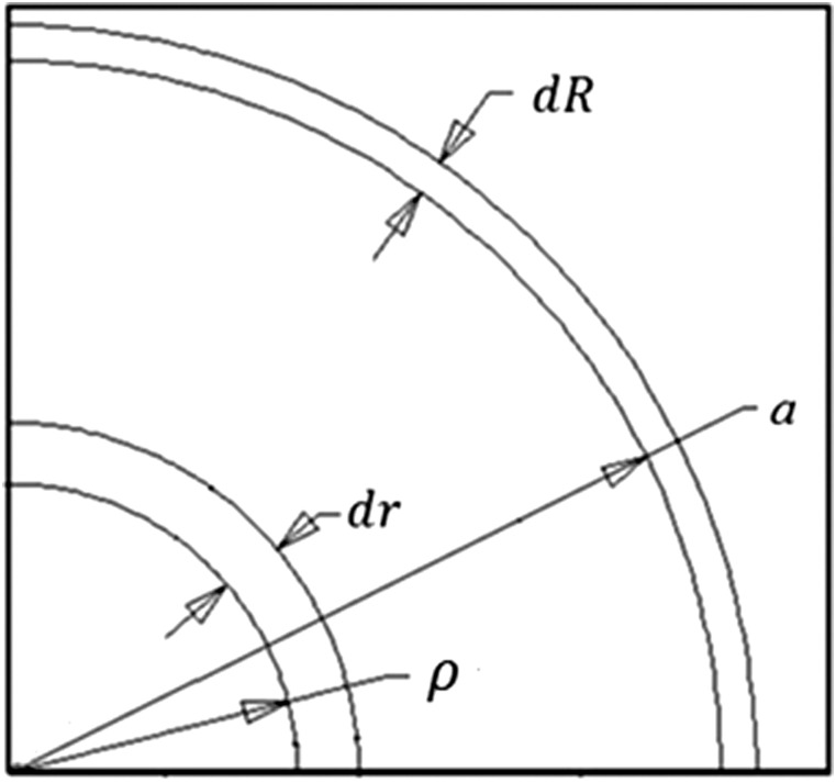
Stretch ratios were calculated by using a volume conservation approach. The material in the annular zone between and was displaced to the annular zone between a+dR and a (Fig. 1) where R and r are radial coordinates. Expressing this relation in equation form
Fig. 1.
Material displaced due to cannula retraction ( needle radius; position of the free surface after needle retraction)
| (3) |
Therefore, the stretch ratio in the radial direction was
| (4) |
The constant s was calculated far away from the cannula where the stress and displacements were zero, and the stretch ratio was equal to unity. From Eq. (1), s was equal to μ.
After calculating the derivative of W, the stress [Eq. (1)] becomes
| (5) |
For the prestress, only the normal stress in the radial direction was considered
| (6) |
2.4. Backflow Model.
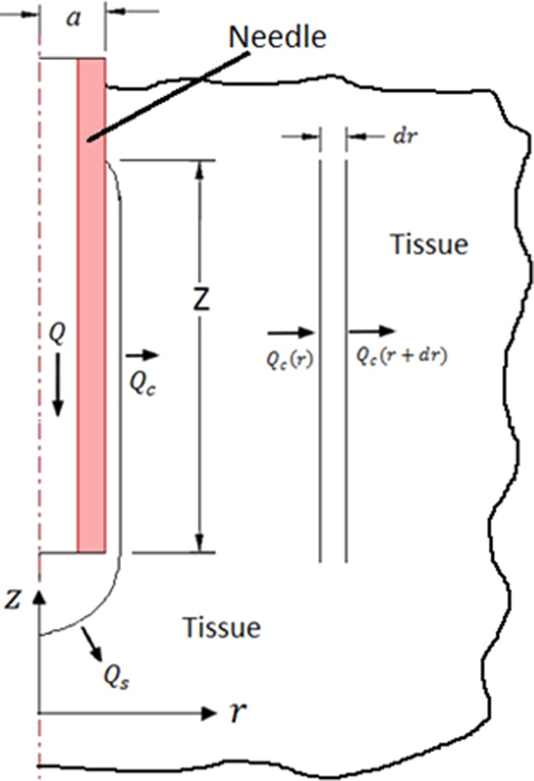
A simplified backflow model was implemented in which calculated prestress was used to estimate backflow distance. The model was based on the model of Morrison et al. [8], in which total flow is infused through a hemisphere at the needle tip and a cylindrical surface surrounding the needle where the tissue is separated from the cannula (Fig. 2). When prestress was present, backflow distances were assumed to be small. Therefore in this study, the pressure loss within the annular backflow region was neglected. Once the needle is inserted and if there is no flow, the stress in the solid matrix of the porous media is equal to the prestress and the pore pressure is zero. However, when infusion is taking place, pore fluid pressure is no longer zero. At the porous media interface, the infusion pressure P 0 was set equal to the total stress in the porous media
Fig. 2.
Mass conservation for cannula infusion with backflow. Radial symmetry was assumed. Q = total flow rate, flow through the spherical surface, flow through the cylindrical surface, cannula outer radius, radial coordinate, longitudinal coordinate, and backflow distance.
| (7) |
where φ is the porosity and p is the pore pressure. Due to continuity, P 0 is equal to p at this interface. A value of 0.6 was taken for the porosity based on our previous hydrogel studies [13].
The flow through the hemisphere at the tip of the cannula was taken to be half that for spherical cavity whose radius is equal to the radius of the needle. The flow into porous tissue is
| (8) |
where k is the tissue permeability. On the cylindrical surface, only unidirectional flow in the radial direction was considered. By doing a mass balance on a section of thickness dr inside the tissue under steady-state conditions and in the absence of sources and sinks of mass (Fig. 2)
| (9) |
Expressing by using Taylor series expansion and neglecting higher order terms
| (10) |
Combining these relations
| (11) |
By using Darcy’s law, the flow rate can be expressed as function of the pressure (p) gradient
| (12) |
where Z is the length of the cylindrical surface which in this study was the backflow distance. Substituting Eq. (12) into (11) and integrating, the pressure distribution was obtained
| (13) |
where C 1 and C 2 are integration constants. To evaluate these constants, the pressure at the interior surface was considered equal to the infusion pressure (P 0). Also a characteristic length L [8] was introduced which was the radial distance where the pressure was zero.
Because the displacement of the surrounding tissue caused by elevated fluid pressure was considered small [14], the radius of the internal cylindrical surface was consider to be equal to the radius of the needle (a). Applying boundary conditions to Eq. (13) and solving for the backflow distance Z resulted in the simplified relation
| (14) |
In this study, a value of cm was used [8]. (Varying this parameter between 2 and 6 cm resulted in only small changes in predicted backflow distance.) For the permeability, a value of was used as reported by Raghavan et al. [9]. Unlike previous studies [8,9], backflow distances did not depend on the porosity but only on the permeability of the porous media. Influence of porosity is implicit in the permeability.
3. Experimental Results
3.1. Infusion Experiments.
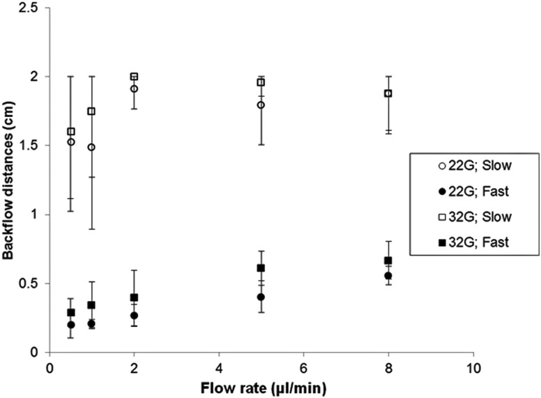
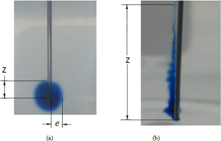
Figure 3 shows measured backflow distances for the two needle diameters, the two insertion speeds, and the flow rates evaluated. When the needle was inserted at high speed, backflow was considerably smaller than at the low insertion speed. For the 1.8 mm/s insertion speed, backflow distances smaller than 1 cm were obtained for both needle diameters. Infusions using the larger 22 gauge needle resulted in a slightly lower backflow distances. Extensive backflow was obtained in experiments performed using the 0.2 mm/s insertion speed, see Fig. 4. In the majority of cases, backflow reached the surface of the agarose hydrogel; therefore, the maximum reported backflow distance was 2 cm. Typical distribution patterns obtained inserting needles at high and low insertion speeds are shown in Figs. 4(a) and 4(b), respectively. For those experiments performed inserting the needle slowly, dye patterns were not as axisymmetric as those obtained when the needle was inserted more rapidly. Also, the tracer penetration distance (e) was smaller and not clearly defined when the needle was inserted slowly.
Fig. 3.
Backflow distances measured at varying flow rates, needle diameters, and insertion speeds (22G = 22 gauge needle; 32G = 32 gauge needle; slow: insertion speed of 0.2 mm/s; fast: insertion speed of 1.8 mm/s; bars indicate standard deviation)
Fig. 4.
Tracer distributions in hydrogel for a needle inserted at (a) 1.8 mm/s and (b) 0.2 mm/s. Both figures show tracer infusions with a flow rate of 0.5 μ/min. Z is the reported backflow distance and is the perpendicular tracer penetration distance in hydrogels (0.7176 mm needle diameter).
3.2. Needle Tip Damage and Plastic Deformation.
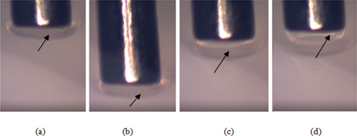
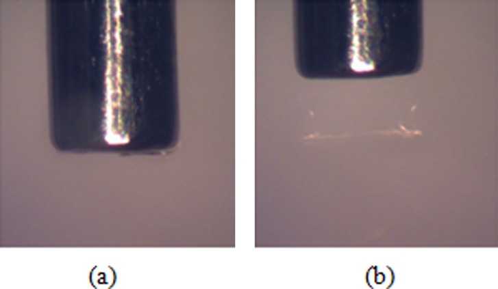
When needles were inserted at the lower speed (0.2 mm/s), accumulation of hydrogel and a large zone of damage was observed at the needle tip. Material was observed to build up and advance at the front of the needle tip during forward insertion, see Fig. 5. During retraction the accumulated material initially followed backwards movement of the needle tip [Fig. 5(c)], but at a certain retraction distance (∼0.3 mm) this material detached. The material build up was not transitory and was maintained after the needle stopped and following needle retraction. Small amounts of accrued material were also observed to go inside the hollow needle tip during insertion [arrow in Fig. 5(d)]. In addition, the zone of accumulated material was wider than the outer cannula diameter contributing to a region of damage wider than the inserted cannula. Build up of hydrogel at the needle tip was not observed when the needle was inserted at higher speed (1.8 mm/s) indicating less material damage during insertion, see Fig. 6.
Fig. 5.
Accumulation of hydrogel at the needle tip during: (a) insertion at 0.2 mm/s, (b) stop, (c) retraction, and (d) detachment (needle diameter = 0.7176 mm)
Fig. 6.
Insertion of the needle at 1.8 mm/s: (a) insertion and (b) retraction (diameter of the needle = 0.7176 mm)
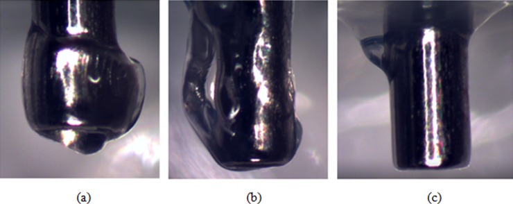
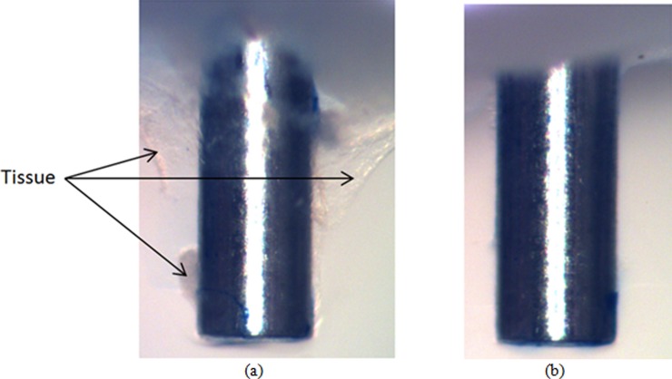
The difference in hydrogel damage modes between insertions at high and low speeds was more evident when the needle was allowed to exit the opposite side of the hydrogel sample. Figures 7(a) and 7(b) show two representative cases of needles inserted at low speed. In Fig. 7(a) there is an approximately symmetric accumulation of hydrogel material at the tip. The more common case, where the material was accumulated on one side of the needle, is shown in Fig. 7(b). Average thickness of accumulated material at the tip in the radial direction was 0.18 mm (±0.078 mm). When the needle was inserted at high speed, no measurable accumulation was observed on the needle tip, see Fig. 7(c). Although not to the same extent as in hydrogel, tissue accumulation at the needle tip was also observed for rat brain samples when the insertion was done slowly. Figure 8(a) shows characteristic behavior for slow needle insertion in which tissue was observed to be torn and detached from the tissue sample. Some level of tissue accumulation was observed for all slow insertion experiments. For fast insertion experiments, a clean needle surface with no tissue accumulation was observed for all experiments, see Fig. 8(b).
Fig. 7.
Needle tip accumulation of hydrogel after passing through a hydrogel slice at (a) and (b) 0.2 mm/s and (c) 1.8 mm/s (diameter of the needle = 0.7176 mm)
Fig. 8.
Needle tip accumulation of tissue after passi through a rat brain tissue sample at (a) 0.2 mm/s and (b) 1.8 mm/s (diameter of the needle = 0.7176 mm)
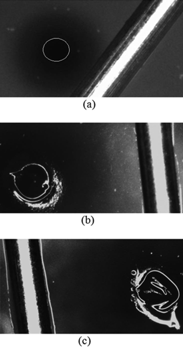
Figure 9(a) shows a surface hole left in the hydrogel after needle retraction. For high speed insertion, holes did not close after needle retraction, and open diameters were measured to be smaller than the needle outer diameter. Table 1 summarizes average diameter measurements, and calculated radial stretch ratios for different diameter needles inserted at high speed. When the needle was inserted at the low speed, holes were not clearly smaller than the inserted needle, see Fig. 9. In the majority of the cases the hole was not circular but irregular in shape. These larger diameter holes reflected greater local damage, and no prestress or backflow was predicted for these low speed cases.
Fig. 9.
Hole in the hydrogel left by the needle after retraction: (a) needle inserted at high speed (the circle outlines the hole); (b) and (c) needle inserted at low speed. The dark region surrounding the needle is the tracer. The needle was placed on hydrogel surface to provide a length scale (diameter of the needle = 0.7176 mm).
Table 1.
Hole diameters and radial stretch ratios for varying gauge needles inserted at a fast insertion speed (1.8 mm/s)
| Needle gauge | Outer diameter of needle (mm) | Hole diameter (mm) | Radial stretch ratio |
|---|---|---|---|
| 28 | 0.365 | 0.2570.023 | 0.7160.064 |
| 22 | 0.717 | 0.5480.040 | 0.7630.055 |
| 20 | 0.908 | 0.6430.047 | 0.7080.052 |
3.3. Prestress Calculation.
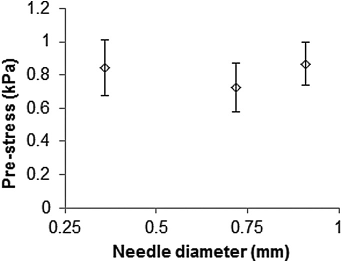
Prestress was calculated for high insertion speed tests. Figure 10 shows the calculated residual stress corresponding to measured radial stretch ratios for varying needle gauge. There was no significant difference in the average stress values, even though needle diameters were considerably different. The average value of prestress for all three gauges was calculated to be kPa. From Eq. (7) the calculated infusion pressure was kPa.
Fig. 10.
Hydrogel prestress for varying needle gauges. Prestress was calculated from hole diameters after fast insertion, see Table 1.
3.4. Backflow Model.
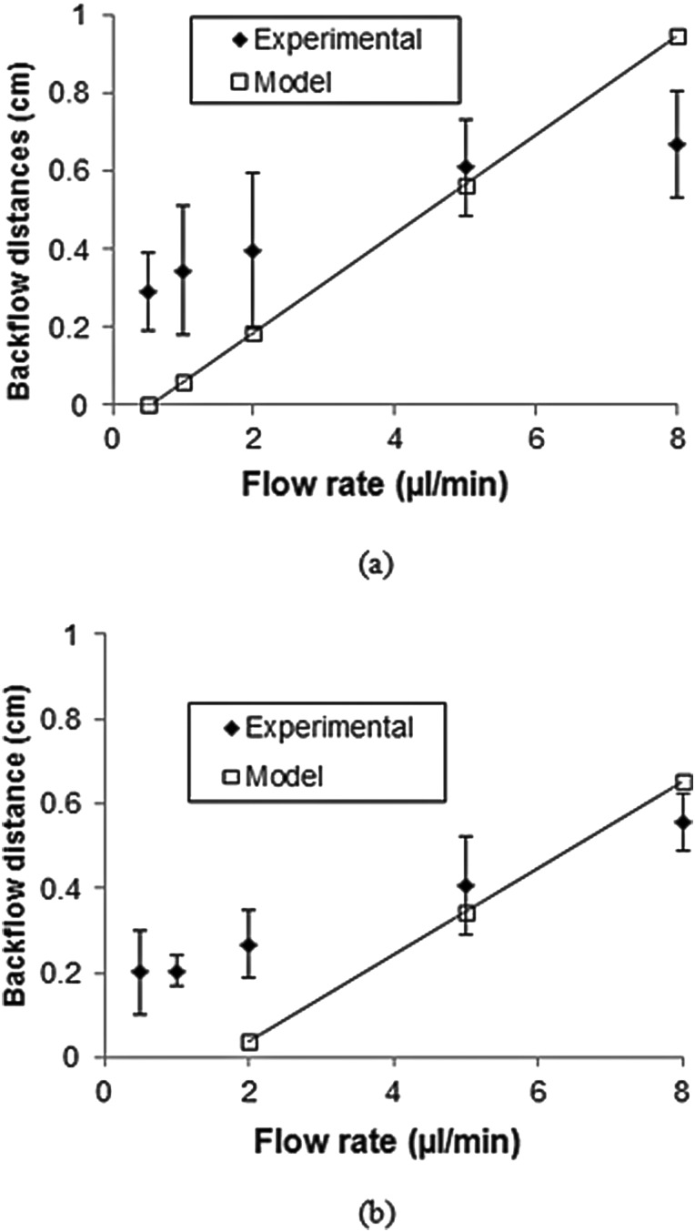
Backflow distance as a function of flow rate was predicted for high insertion speed tests. Figure 11 compares experimental and calculated backflow distances for 32 and 22 gauge needles. Calculated backflow values were determined to be greater than experimentally measured values at high flow rates, but predicted values were smaller than experimental values at low flow rates. It should be noted that the model did not apply when the flow rate was lower than 0.3 μl/min for the 32 gauge needle and 2 μl/min for the 22 gauge needle in which case all the infusate was infused at the cannula tip (hemisphere at end of needle) and no backflow along the cylindrical surface was predicted.
Fig. 11.
Predicted and experimental backflow distances for (a) 32 gauge and (b) 22 gauge needles
4. Discussion
In this study, influence of insertion speed on backflow was investigated using an agarose hydrogel which has been previously used as a facsimile of brain tissue for exploratory experiments [9,13,15,16]. The advantage of using this tissue phantom is that it is transparent and allows for direct measurement of backflow distances.
Some variation in the needle insertion speed was expected since micrometers were driven by hand. However, backflow and damage findings were found to be significantly different for the two speed levels tested, and an important reduction in backflow was obtained by inserting the needle at a faster speed (P value < 0.01). This improvement may be explained by lower levels of local hydrogel damage that were observed at this insertion speed. This finding is consistent with tissue damage observations reported by Bjornsson et al. [11] for electrodes which were inserted in brain tissue at similar speeds; they found that inserting electrodes at a faster speed produced less tissue deformation and damage consistent with vascular rupture. In hydrogel, local damage was assessed by observing accumulation of hydrogel at the needle tip during needle insertion and by the extent of plastic deformation in the hydrogel after needle removal. For the faster insertion speed, there was minimal observed accumulation of hydrogel at the needle tip, which corresponded to smaller backflow distances. On the other hand, when the needle was inserted more slowly, extensive accumulation of material at the needle tip was observed, and the holes left by the needles were irregularly shaped. It is likely that the accumulated material at the tip created a channel in the hydrogel that was larger than the outer diameter of the needle, forming a gap between the tissue and cannula that promoted extensive backflow. In most test cases, backflow was observed to reach the surface of the sample. To determine whether brain tissue behaves similarly to hydrogel, local damage experiments were also performed. Insertion experiments on excised tissue samples indicated that similar patterns of speed sensitive tissue accumulation occur in brain tissues when subject to the same conditions. Tissue accumulation was observed at the needle tip and the extent of accumulation was observed to be dependent on the needle insertion velocity. Overall, these results indicate that local tissue damage and backflow may be avoided by using an appropriate insertion speed. Backflow and prestress studies in brain tissue will be the focus of future studies.
Comparable backflow distances were obtained at the faster insertion speed and these backflow distances were smaller than those measured by Raghavan et al. [9] in hydrogel infusion experiments. This was probably due to differences in local hydrogel conditions near the needle. In their experiments the needle was put in place before the hydrogel solidified; therefore, no prestress was present due to needle insertion. These results suggest that the presence of prestress may reduce the extent of backflow. In hydrogel, evidence of prestress was the reduction of the insertion hole diameter after needle retraction. In brain tissues, White et al. [17] have conducted similar needle retraction experiments to investigate local tissue damage. They also saw that holes left in tissue after needle retraction were always smaller than the needle suggesting that prestress may also exist in brain tissues. Other evidence for prestress in tissues is indirect and based on studies measuring needle penetration and retraction forces in hydrogels and brain tissue [15,18,19]. These forces may result from radial prestress and friction, as well as, adhesion between the tissue and the needle surface. In addition, Chen et al. [15] have reported penetration forces to be similar between 0.6% (w/v) hydrogels and brain tissues which suggests similar interacting forces for tissue phantoms and brain tissue. However, it should be noted that hydrogels and brain tissues do not share the same mechanical properties, e.g., yield strength [20], and the mechanics of the damage may be different between materials.
In general, prestress and backflow will depend not only on elastic material properties but also on the plastic properties like yield strength. In this study, a simple approach based on an experimental measure of hydrogel deformation, i.e., changes in open hole diameter after needle retraction, was used to calculate the prestress. In this way, prestress was estimated directly without using plastic properties of the material which are poorly known. This approach makes several assumptions including that the material was incompressible, all displaced material conformed around the needle with no accumulation at the needle tip, there were no hardening effects, and plain strain conditions existed. Our current model also does not account for consolidation effects due to compaction of tissue at the needle-tissue interface. Rather, neo-Hookean mechanical properties were used based on a previous brain tissue slice indentation study by our group (Lee et al. [12]) in which mechanical properties were calculated for varying Poisson ratio. Any consolidation of tissues would also have occurred during compressive indentation testing.
In the presence of prestress, backflow distances were measured to be slightly shorter for larger diameter needles. While it might be expected that larger diameter needles have larger contact stress with the hydrogel, the prestress estimated using hole contraction measurements predicted similar values for varying gauges. Larger diameter needles also have a greater surface area at the tip of the needle and along the cylindrical surface around the needle. Because of this greater surface area, less backflow distance is required for larger needles for the same flow rate and prestress since they have greater surface area for infusate penetration into hydrogel compared to smaller needles. When considering only the pressure necessary to open a gap between the needle and an elastic material (without prestress), Morrison et al. [8] and Raghavan et al. [9] found that the backflow was higher for larger needle diameters. This is because only an elastic deformation around the needle was considered.
When compared to experimentally measured backflow distances, the simplified backflow model assumed a linear increase in backflow distance with increasing flow rate. This model tended to underpredict backflow distances at lower flow rates and overpredict backflow at higher flow rates. This discrepancy may be partially due to the tracer penetration distance which was maximum at low flow rates; in addition to certain model assumptions. For example, the idealized hemisphere and cylindrical geometry; also, the model assumed an unidirectional flow with a constant infusion pressure along the fluid-tissue interface. However, some loss of pressure likely occurs within the annular gap between the needle and tissue, and in this case, the fluid pressure within the tip region should be higher than the prestress value used in this study. With higher infusion tip pressure, more infusate is advected into tissue at the needle tip, and less infusate flows back to create backflow. This effect becomes larger at higher flow rates and explains backflow overprediction as flow rate increased.
Accumulation of material at the needle tip and the corresponding damage in the surrounding media was a main cause of backflow; therefore, the needle tip geometry may be an important factor since different tips may result in different patterns of material accumulation. In the present study, only blunt tip needles were tested but it is possible that sharp tip needles produce less backflow if they move more material away from the needle or if less tissue sticks to the needle.
5. Conclusions
For hydrogel infusions, the extent of backflow was found to vary with needle insertion speed. When the needle was inserted slowly, an accumulation of deformed material at the tip of the needle produce a region of damage that resulted in a gap between the needle and tissue that promoted backflow. This accumulation was also observed in brain tissue samples at a slow insertion speed. On the other hand, when the needle was inserted faster, contact between the surrounding media and the cannula was maintained. In hydrogels, the resulting prestress considerably reduced backflow. For these faster insertions, no significant difference in the prestress as a function of the needle diameter was found. This finding was reflected in small differences in measured backflow for varying needle gauge. For varying flow rates, the simplified backflow model tended to underpredict backflow distances at lower flow rates and overpredicted backflow at higher flow rates. Results of ex vivo tests and comparison with previous studies indicated that similar rate-dependent damage may occur in tissues, and future studies will determine the influence of needle insertion speed on backflow in biological tissues.
Acknowledgment
This work was supported by the Universidad del Valle, Cali, Colombia, by the Fulbright-COLCIENCIAS-DNP grant, and by award number R01NS063360 from the National Institute of Neurological Disorders and Stroke. The content is solely the responsibility of the authors and does not necessarily represent the official views of the National Institute of Neurological Disorders and Stroke or the National Institutes of Health.
Contributor Information
Fernando Casanova, Escuela de Ingenieria Mecanica, Universidad del Valle, Carrera 13 No. 100-00, Cali, Colombia; Department of Mechanical, and Aerospace Engineering, University of Florida, Florida 32611, e-mail: bando1271@yahoo.es.
Paul R. Carney, Department of Pediatrics, Neurology, Neuroscience, and, J. Crayton Pruitt Family, Department of Biomedical Engineering, Wilder Center of Excellence, for Epilepsy Research, University of Florida, 1600 SW Archer Road, Gainesville, Florida 32610, e-mail: carnepr@peds.ufl.edu
Malisa Sarntinoranont, Department of Mechanical, and Aerospace Engineering, 212 MAE A 212, Gainesville, Florida 32611, e-mail: msarnt@ufl.edu.
References
- [1]. Allard, E. , Passiraini, C. , and Benoit, J. P. , 2009, “Convection Enhanced Delivery of Nanocarriers for the Treatatment of Brain Tumors,” Biomaterials, 30, pp. 2302–2318. 10.1016/j.biomaterials.2009.01.003 [DOI] [PubMed] [Google Scholar]
- [2]. Bobo, R. H. , Laske, D. W. , Akbasak, A. , Morrison, P. F. , Dedrick, R. L. , and Oldfield, E. H. , 1994, “Convection-Enhanced Delivery of Macromolecules in the Brain,” Proc. Natl. Acad. Sci. U.S.A., 91, pp. 2076–2080. 10.1073/pnas.91.6.2076 [DOI] [PMC free article] [PubMed] [Google Scholar]
- [3]. Rogawski, M. A. , 2009, “Convection-Enhanced Delivery in the Treatment of Epilepsy,” Neurotherapeutics, 6(2), pp. 344–351. 10.1016/j.nurt.2009.01.017 [DOI] [PMC free article] [PubMed] [Google Scholar]
- [4]. Chen, M. Y. , Lonser, R. R. , Morrison, P. F. , Governale, L. S. , and Oldfield, E. H. , 1999, “Variables Affecting Convection-Enhanced Delivery to the Striatum: A Systematic Examination of Rate of Infusion, Cannula Size, Infusate Concentration, and Tissue-Cannula Sealing Time,” J. Neurosurg., 90, pp. 315–320. 10.3171/jns.1999.90.2.0315 [DOI] [PubMed] [Google Scholar]
- [5]. Yin, D. , Forsayeth, J. , and Bankiewicz, K. S. , 2010, “Optimized Cannula Design and Placement for Convection-Enhanced Delivery in Rat Striatum,” J. Neurosci. Methods, 187, pp. 46–51. 10.1016/j.jneumeth.2009.12.008 [DOI] [PMC free article] [PubMed] [Google Scholar]
- [6]. Ivanchenko, O. , and Ivanchenko, V. , 2011, “Designing and Testing of Backflow-Free Catheters,” ASME J. Biomech. Eng., 133, p. 061003. 10.1115/1.4004286 [DOI] [PubMed] [Google Scholar]
- [7]. Neeves, K. B. , Lo, C. T. , Foley, C. P. , Saltzman, W. M. , and Olbricht, W. L. , 2006, “Fabrication and Characterization of Microfluidic Probes for Convection Enhanced Drug Delivery,” J. Controlled Release, 111, pp. 252–262. 10.1016/j.jconrel.2005.11.018 [DOI] [PubMed] [Google Scholar]
- [8]. Morrison, P. F. , Chen, M. Y. , Chadwick, R. S. , Lonser, R. R. , and Oldfield, E. H. , 1999, “Focal Delivery During Direct Infusion to Brain: Role of Flow Rate, Catheter Diameter, and Tissue Mechanics,” Am. J. Physiol., 277, pp. 1218–1229. [DOI] [PubMed] [Google Scholar]
- [9]. Raghavan, R. , Mikaelian, S. , Brady, M. , and Chen, Z. J. , 2010, “Fluid Infusions From Catheters Into Elastic Tissue: I. Azimuthally Symmetric Backflow in Homogeneous Media,” Phys. Med. Biol., 55, pp. 281–304. 10.1088/0031-9155/55/1/017 [DOI] [PubMed] [Google Scholar]
- [10]. Alterovitz, R. , Goldhere, K. , Pouliot, J. , Taschereau, R. , and Hsu, I. , 2003, “Needle Insertion and Radioactive Seed Implantation in Human Tissues: Simulation and Sensitivity Analysis,” Proceedings of the 2003 IEEE International Conference on Robotics and Automation, Taipei, September, pp. 14–19. [Google Scholar]
- [11]. Bjornsson, C. S. , Oh, S. J. , Al-Kofahi, Y. A. , Lim, Y. J. , Smith, K. L. , Turner, J. N. , De, S. , Roysam, B. , Shain, W. , and Kim, S. J. , 2006, “Effects of Insertion Conditions on Tissue Strain and Vascular Damage During Neuroprosthetic Device Insertion,” J. Neural Eng., 3, pp. 196–207. 10.1088/1741-2560/3/3/002 [DOI] [PubMed] [Google Scholar]
- [12]. Lee, S. J. , Sun, J. , Flint, J. J. , Gou, S. , Xie, H. K. , King, M. A. , and Sarntinoranont, M. , 2011, “Optically Based-Indentation Technique for Acute Rat Brain Tissue Slices and Thin Biomaterials,” J. Biomed. Mater. Res. Part B, 97B, pp. 84–95. 10.1002/jbm.b.31789 [DOI] [PMC free article] [PubMed] [Google Scholar]
- [13]. Chen, X. , Astary, G. W. , Sepulveda, H. , Mareci, T. H. , and Sarntinoranont, M. , 2008, “Quantitative Assessment of Macromolecular Concentration During Direct Infusión Into an Agarose Hidrogel Phantom Using Contrast-Enhanced MRI,” Magn. Reson. Imaging, 26, pp. 1433–1441. 10.1016/j.mri.2008.04.011 [DOI] [PMC free article] [PubMed] [Google Scholar]
- [14]. Ivanchenko, O. , Sindhwani, N. , and Linninger, A. , 2010, “Experimental Techniques for Studying Poroelasticity in Brain Phantom Gels Under High Flow Microinfusion,” ASME J. Biomech. Eng., 132, p. 051008 10.1115/1.4001164 [DOI] [PubMed] [Google Scholar]
- [15]. Chen, Z. J. , Gillies, G. T. , Broaddus, W. C. , Prabhu, S. S. , Filmore, H. , Mitchell, R. M. , Corwin, F. D. , and Fatouros, P. P. , 2004, “A Realistic Brain Tissue Phantom for Intraparenchymal Infusion Studies,” J. Neurosurg., 101, pp. 314–332. 10.3171/jns.2004.101.2.0314 [DOI] [PubMed] [Google Scholar]
- [16]. Lee, S. J. , Pishko, G. L. , Astary, G. W. , Mareci, T. H. , and Sarntinoranont, M. , 2009, “Characterization of an Anisotropic Hydrogel Tissue Substrate for Infusion Testing,” J. Appl. Polymer Sci., 114, pp. 1992–2002. 10.1002/app.30639 [DOI] [PMC free article] [PubMed] [Google Scholar]
- [17]. White, E. , Bienemann, A. , Malone, J. , Megraw, L. , Bunnum, C. , Wyatt, M. , and Gill, S. , 2011, “An Evaluation of the Relationships Between Catheter Design and Tissue Mechanics in Achieving High-Flow Convection-Enhanced Delivery,” J. Neurosci Methods doi: 10.1016/j. jneumeth. 2011.04.027. [DOI] [PubMed] [Google Scholar]
- [18]. Howard, M. A. , Abkes, B. A. , Ollendieck, M. C. , Noh, M. D. , Ritter, R. C. , and Gillies, G. T. , 1999, “Measurement of the Force Required to Move a Neurosurgical Probe Through in vivo Human Brain Tissue,” IEEE Trans. Biomed. Eng., 46(7), pp. 891–894. 10.1109/10.771205 [DOI] [PubMed] [Google Scholar]
- [19]. Sharp, A. A. , Ortega, A. M. , Restrepo, D. , Curran-Everett, D. , and Gall, K. , 2009, “in vivo Penetration Mechanics and Mechanical Properties of Mouse Brain Tissue at Micrometer Scales,” IEEE Trans. Biomed. Eng., 56, pp. 45–53. 10.1109/TBME.2008.2003261 [DOI] [PMC free article] [PubMed] [Google Scholar]
- [20]. Franceschini, G. , Bigoni, D. , Regitnig, P. , and Holzapfel, G. A. , 2006, “Brain Tissue Deform Similarly to Filled Elastomers and Follows Consolidation Theory,” J. Mech. Phys. Solids, 54, pp. 2592–2620. 10.1016/j.jmps.2006.05.004 [DOI] [Google Scholar]


