Short abstract
Currently, aortic valve replacement procedures require a sternotomy and use of cardiopulmonary bypass (CPB) to arrest the heart and provide a bloodless field in which to operate. A less invasive alternative to open heart surgery is transapical or transcatheter aortic valve replacement (TAVR), already emerging as a feasible treatment for patients with high surgical risk. The bioprosthetic valves are delivered via catheters using transarterial or transapical approaches and are implanted within diseased aortic valves. This paper reports the development of a new self-expanding stent for minimally invasive aortic valve replacement and its delivery device for the transapical approach under real-time magnetic resonance imaging (MRI) guidance. Made of nitinol, the new stent is designed to implant and embed a commercially available bioprosthetic aortic valve in aortic root. An MRI passive marker was affixed onto the stent and an MRI active marker to the delivery device. These capabilities were tested in ex vivo and in vivo experiments. Radial resistive force, chronic outward force, and the integrity of bioprosthesis on stent were measured through custom design dedicated test equipment. In vivo experimental evaluation was done using a porcine large animal model. Both ex vivo and in vivo experiment results indicate that the self-expanding stent provides adequate reinforcement of the bioprosthetic aortic valve and it is easier to implant the valve in the correct position. The orientation and positioning of the implanted valve is more precise and predictable with the help of the passive marker on stent and the active marker on delivery device. The new self-expanding nitinol stent was designed to exert a constant radial force and, therefore, a better fixation of the prosthesis in the aorta, which would result in better preservation of long-term heart function. The passive marker affixed on the stent and active marker embedded in the delivery devices helps to achieve precise orientation and positioning of the stent under MRI guidance. The design allows the stent to be retracted in the delivery device with a snaring catheter if necessary. Histopathology reports reveal that the stent is biocompatible and fully functional. All the stented bioprosthesis appeared to be properly seated in the aortic root.
Keywords: minimally invasive aortic valve replacement, self-expanding nitinol stents, shape memory materials, real-time MRI guidance
1. Introduction
Aortic valve stenosis, characterized by narrowing of the aortic valve opening is the most common valvular heart disease in elderly patients. Open heart surgery for aortic valve replacement (AVR) with mechanical or biological heart valves is the treatment of choice for symptomatic or severe aortic valve stenosis. In the last few years, TAVR has emerged as a less invasive alternative to open heart surgery for patients at high surgical risk for AVR. The bioprosthetic valves are delivered through catheters using transarterial or transapical approaches and are implanted within the diseased aortic valve. Many medical experts predict that these new procedures could revolutionize the treatment of aortic valve disease [1–3].
The prosthesis used for percutaneous transcatheter valve replacement or transapical aortic valve replacement are comprised of a bioprosthetic valve affixed (sewn) into a balloon-expandable or self-expanding stent.
Made of stainless steel, platinum, cobalt-alloy, or tantalum, balloon-expandable stents are expanded by plastic deformation caused by the inflation of a balloon placed inside the stent.
Self-expanding stents made of shape memory materials such as nitinol allow for easier anatomically correct placement and flexible reinforcement of the bioprosthetic aortic valve. Self-expanding stents instead of being deformed to the vessel diameter expand by simply returning to their equilibrium shape.
Since 2002, when the first TAVR was performed in humans [4], there have been several TAVR technologies developed in an attempt to address the challenges of this new procedure.
The Edwards SAPIEN heart-valve system (Edwards Lifesciences Inc., Irvine, CA) consists of a trileaflet bovine pericardial valve mounted within a tubular, slotted, stainless steel or cobalt-chromium alloy balloon-expandable stent [1,5–8]. The valve is positioned under fluoroscopic guidance from a perpendicular projection and deployed with rapid pacing in order to control blood pressure below 40 mmHg, to avoid valve migration during deployment. The valve is implanted in the subcoronary position using an antegrade or retrograde transfemoral or transapical approach, and feasibility studies and clinical trials in Europe, the U.S., and Canada have been performed.
The CoreValve prosthesis (developed by CoreValve Inc. Irvine, CA) uses a trileaflet porcine pericardial valve mounted on a self-expanding nitinol frame [9–11]. The self-expandable nitinol frame is anchored by the high radial force area in the aortic annulus and by the low radial force area in the ascending aorta. The CoreValve prosthesis can be implanted via the transfemoral approach using an iliofemoral vascular access or transsubclavian approach [12] in cases where the femoral access is not suitable. Fluoroscopic guidance is employed in order to achieve accurate positioning of the bioprosthesis.
Engager™ System (Medtronic Inc., Minneapolis, MN) uses a bovine pericardial tissue valve affixed in a self-expanding nitinol frame and a transapical delivery system with support arms facilitating anatomically correct positioning and axial fixation [13]. Another valve system that incorporates features that facilitate anatomical positioning and orientation in relation to the native valve is JenaClip (JenaValve Inc., Germany). JenaClip is a porcine valve mounted on a nitinol stent, with feeler-guided positioning and clipping fixation on the diseased leaflets [14].
Acurate TA (Symetis Inc., Geneva, Switzerland) is a new transapical valve system that received Conformité Européene (CE) Marking approval in 2011 [15]. Symetis Acurate valve is a self-expandable nitinol porcine valve, delivered transapically, and designed for subcoronary implantation. The Symetis valve has two specific features, a stabilization arch, meant to prevent tilting of the valve during deployment, and a so-called “upper crown,” the most distal part of the stent body, designed to provide technical feedback for positioning.
Other types of minimally invasive aortic valve prosthesis and replacement systems (such as LotusTM—Boston Scientific Inc., or Direct Flow—Direct Flow Medical Inc.) have been proposed or are in various stages of development, but all face a common set of technical challenges, such as: difficulty to achieve correct positioning and orientation, migration, embolization, and operative complications.
Typically, the imaging used for percutaneous valve replacement is fluoroscopy with adjuvant echocardiography. Fluoroscopic guidance only provides 2D visualization with limited soft tissue contrast. Contrast agents must be repeatedly injected to determine the location of the aortic annulus and coronary ostia. Moreover, the patient and physician are exposed to radiation during the intervention.
MRI provides excellent visualization, particularly in its ability to deliver high-resolution images of blood filled structures, without additional risk of radiation or contrast agent reaction. One of the strengths of real-time MRI is the ability to interactively adjust image acquisition, reconstruction, and display parameters during the scan. MRI also provides the ability to assess results, such as ventricular and valvular function and myocardial perfusion immediately after intervention. However, the MRI environment has special requirements for the safety and compatibility of the aortic prostheses and their corresponding delivery devices.
The design geometry of the aforementioned stents is based on a diamond cell shape. This configuration may induce extra stress on the bioprosthetic valve from crimping to deployment. In addition, the prostheses implanted with the present beating heart approaches are of an unknown durability.
In this study, we propose to design a new stent based on a chevron like cell and a corresponding delivery device for a commercially available bioprosthetic valve (with known durability) and use real-time MRI guidance (rtMRI) for the transapical aortic valve implantation.
2. Materials and Methods
2.1. Stent Design.
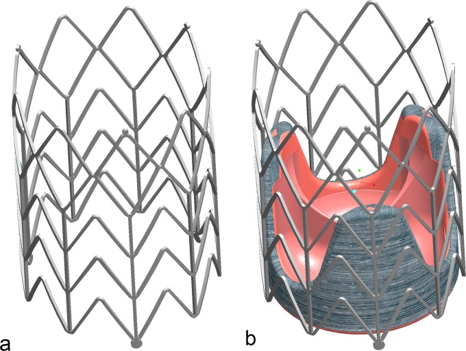
TAVR carries risks such as migration from the optimum position, coronary occlusion, valve malpositioning, embolization, or early deployment. To overcome these problems reported in previous research reports [4,7,9,11,14,16–24], we designed a new self-expanding stent dedicated to be used for aortic valve replacement. The stent (Fig. 1) is designed to maintain and affix a commercially available bioprosthetic aortic valve such as Toronto SPV (St. Jude Medical, Inc, Maple Grove, MN) or modified Freestyle (Medtronic Inc., Minneapolis, MN) in the aortic root.
Fig. 1.
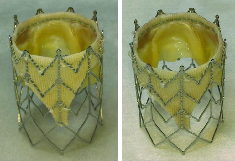
(a) Self- expanding stent; (b) bioprosthetic valve affixed in self-expanding stent
Alongside with the correct position and orientation, the prosthesis must be adequately fixed in the aortic root such that migration or embolization does not occur despite high blood pressures.
This self-expanding stent provides more anatomically correct placement and adequate support for the bioprosthetic aortic valve. Because the aortic valve lies in close proximity to both the mitral valve and the coronary ostia, the correct position and orientation of the implanted valve is critical. Misplacement of the prosthesis could result in mitral valve damage or can block the coronary ostia inducing a life threatening ischemic condition. Also, deployment of the prosthesis in a suboptimal location can result in poor hemodynamic performance with severe paravalvular leakages and/or high gradients.
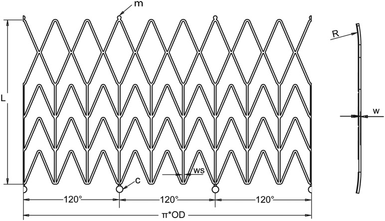
To help orient the stent, one passive marker (m) made from high-density metal (ferromagnetic stainless steel, monitored using MRI or gold, platinum, tantalum monitored using X-ray imaging) is affixed on the distal end of one of the longitudinal stent struts (Fig. 2). We then align this marker with one of the valve commissures to aid visualization in the MRI in order to make the orientation and positioning of the implanted valve more precise.
Fig. 2.
Unfolded geometry with technical details of the stent
The stent is a chevronlike cylinder made of a biocompatible nickel-titanium alloy (nitinol), which assumes a “preprogrammed” final configuration upon release from the delivery system and exposure to body temperature. The stent has nine rods—three of these are aligned with the valve commissures (Fig. 1(b))—and a chevron repeating pattern along the length of the cylinder (Fig. 2), with flared ends (R). The nine rods connected by the chevron-shaped struts form a nine-sided polygon. We consider that the design based on chevron repeating pattern along the length of the stent presents advantages over the preview stent design based on diamond cell configuration. In this design, the length of the stent stays unchanged at both crimped and expanded status, and therefore, it prevents stress on the bioprosthetic valve especially at commissures suturing areas. The chevron geometry also prevents the migration of the stent at systole (high blood pressure) because of the self-anchoring properties of the chevron spikes. Another important feature is the flare end that also helps to better affix the stent in the aortic root.
Unfolded geometry with technical details of the stent construction is presented in Fig. 2. The values of the geometry parameters, diameter (D), length (L), thickness (w) and strut width (ws) give the radial force and flexibility (strength) of the stent.
Pressures applied to a blood vessel will cause a hoop force, or circumferential loading of the vessel. The hoop force per unit length of vessel (fH) is defined in Ref. [25] as fH = p · d/2, where p is the pressure and d is the vessel diameter. Assuming a systolic pressure in the aorta of p = 120 mmHg and a 25 mm vessel diameter, a hoop force of 0.2 N will result. After insertion into the aortic root, the stent is released and is expands until it comes into contact with the aorta. At this point, further expansion of the stent is prevented. Because the stent did not expand to its preset shape, it continues to exert a low outward force, known as chronic outward force [26]. Therefore, we can associate the hoop force with chronic outward force. Otherwise, the stent needs to have enough radial force to stay in position but not to exert excessive radial force to the aortic root. To reach the proper chronic outward force (0.2 N), the stent should be 1–2 mm wider than the aortic root diameter and have the design parameters of stent thickness w = 0.43 mm and strut width ws = 0.5 mm. Unconstrained expanded stent diameter (D) and length (L) were chosen to properly accommodate a commercially available bioprosthesis in the aortic root of the animals for experiments. We found that the diameter of the aortic root of the average swine we operated on was in the range of 21–27 mm. For an aortic root with the most common dimension as 24–25 mm in diameter, a valve with 25 mm affixed with a stent with a 26 mm diameter was a good fit. A stent length of 35 mm was found to provide space for supporting commissure and extra length for proper scaffolding of the bioprosthesis in the aortic root.
In order to allow for retraction and redelivery of the prosthesis during the placement procedure, circular holders (c) were designed on the bottom of the stent (Fig. 2). The circular holders can be grasped by a snare loop catheter, which is then used to hold or retract the prosthesis for repositioning. The stent can be reconstrained if it has been partially released (approximately 66%) but cannot be reconstrained once it has been completely released. Partial release of stent not only helps the surgeon to better observe the stent's position and orientation on the MR image, it also helps to adjust the position and orientation of the stent. The loop snare wire system also prevents early or accidental prosthesis deployment.
The stent is machined from a nitinol tube using computer numerical control (CNC) Nd:YAG laser cutting followed by post cut shape forming. Subsequently, electropolishing techniques are used to remove the heat affected zone, recast materials, and sharp edges yielding a stent with smooth surfaces.
2.2. Stent Delivery System Design.
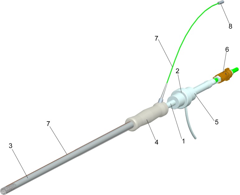
To deliver the bioprosthetic valve inside the aortic root a delivery device was developed. The delivery device is made from plastic materials and is fully MRI compatible (Fig. 3).
Fig. 3.
The bioprosthesis delivery systems with loop coil antenna
The bioprosthetic valve was sutured into a self-expanding stent; then the stent was crimped and placed inside outer sheath at the distal end of the delivery system (Fig. 3). Upon release of the stent by retraction of the outer sheath, the stent together with the bioprosthetic valve expands to its predetermined diameter.
The deployment system (Fig. 3) is a dual lumen, coaxial tube system consisting of an inner carrier rod (1), which connects to the back handgrip (2), and a coaxial outer sheath (3), which connects to the back handgrip (4). The interior carrier rod (1) with handle pushes the prosthesis for deployment and through an interior channel provides access for a loop snare wire.
To prevent blood leakage, a modified Check-Flo® Introducer set French size 14 (Cook, Bloomington, IN) is used inside of the spacer (5). The loop snare wire system (6) holds the stent and prevents accidental deployment. To improve visibility of the delivery device and bioprosthesis in the MR image before deployment a loop coil antenna was embedded in the delivery device. The loop coil antenna (7) was constructed and adapted to the valve delivery system in ISO class 7 cleanroom. The loop coil was manufactured using insulated 0.127 mm magnet copper wire (Heraeus Medical Components Inc., St. Paul, MN) and the coil length was adjusted to 28 mm with 0.66 mm outer diameter. As a transmission line for the loop coil antenna a 0.152 mm profile twisted pair was used. The whole structure was insulated by using medical grade polyester heat shrink tubing. The loop coil antenna was matched to 50 Ω and tuned to Larmour frequency of 1.5T MRI scanner. The matching/decoupling circuit box was attached to the loop coil antenna by microminiature coaxial (MMCX) type rf connectors (8) (Microstock Inc., West Point, PA). The loop coil antenna was fixed into the groove cut on exterior tube of valve delivery system by using medical grade ultraviolet (UV) adhesive (Loctite 3211, Loctite Inc. Rocky Hill, CT). The delivery system can be inserted through a 5–12 mm VersaStep™ Plus trocar (Tyco Healthcare Group LP, North Haven, CT) and is fully MRI compatible.
2.3. Stent Material.
Superelasticity, shape memory effect, excellent biocompatibility, corrosion resistance, MRI compatibility, and resistance to fatigue make nitinol the material of choice for medical applications, especially for stents.
The corrosion resistance, biocompatibility, and premature stent failures reported in some clinical studies are the subjects of research and are influenced by the technology of stent fabrications and methods of surface preparation [27–29]. Properly treated nitinol stents are very resistant to corrosion and are fully biocompatible [30].
Nitinol is MR safe and produces low susceptibility artifacts in MR image, similar to pure titanium. Nitinol's MRI compatibility offers the possibilities to use rtMRI for continuous evaluation of the delivery of the prosthesis throughout the procedure. For example, TAVR can be performed on the beating heart without requiring ventricular unloading.
For stent fabrication we chose a nitinol tube with o.d. = 5.842 mm and i.d. = 4.978 mm. Material composition (per ASTM 2063) was: 55.91%Ni weight and the balance Ti. Mechanical properties for this material are: loading plateau stress (at 4% strain) 381.9 MPa; ultimate tensile strength 1261.9 MPa; permanent set (after 8% strain) 0.50%.
2.4. Experiment Setup for Radial Force Measurement.
First, we tested the new nitinol stent in ex vivo experiments to determine the chronic outward force, radial resistive force, MRI compatibility, and integrity of bioprosthetic valve after each crimping.
Chronic outward force, defined by Stoeckel [26], is a measure of the force the stent exerts on the artery as it tries to expand to its nominal diameter. The radial resistive force [26] is a measure of the force the stent exerts as it resists squeezing by constriction of the artery.
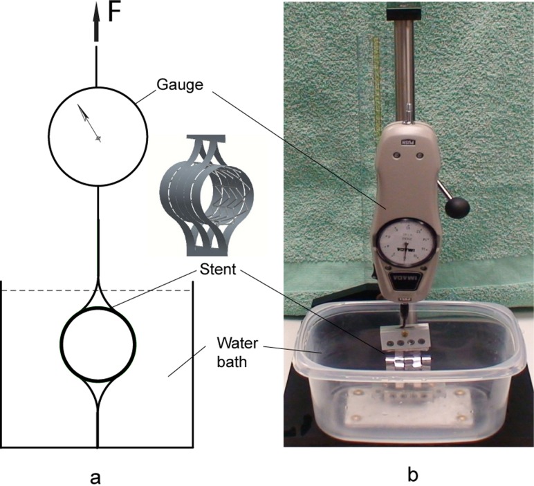
The critical parameters, chronic outward force, and radial resistive force were measured with a custom designed device presented in Fig. 4. The device consists of two sets of constraining loops; one set is connected to the base and the other is located in the opposite side of the stent and actuated with a force measured by a mechanical force gauge—model PS-20 (Imada Inc., Northbrook, IL). The test was performed in a temperature controlled (37 °C ± 1°) water bath.
Fig. 4.
Device for radial force measurement
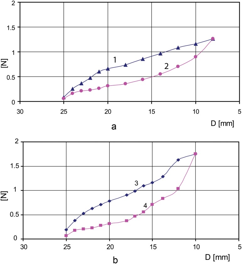
The stent sample (without bioprosthesis) in a fully expanded state (26 mm) was placed into the constraining loops (Fig. 4) of the testing device, and the device was actuated to crimp the stent to its minimum size (8 mm). Then the force was reversed until the stent achieved its fully expanded state of 26 mm diameter. The forces used to contract and expand the stent were incrementally recorded for each 1 mm change in stent diameter. The measurements were repeated for n = 5 stent samples with the same diameter.
The testing experiment was repeated for the stent/valve ensemble for n = 5 stent/valve samples. For each stent (26 mm in diameter), a matched size (25 mm) Toronto SPV aortic valve was sutured inside. The stent/valve sample in a fully expanded state was placed in the testing device (Fig. 4), and the device was actuated to shrink the stent/valve to its minimum size (10 mm). Then the force was reversed until the stent/valve achieved its fully expanded state of 26 mm in diameter. The minimum compressed stent/valve diameter was limited to 10 mm because this type of bioprosthetic valve has a tick cuff. The force to squeeze the stent was reported in Fig. 5 as radial resistive force per unit length and the force the stent exerted to gain its fully extended diameter was reported as chronic outward force per unit length in N. MRI compatibility was tested using the same MRI sequences that we used for aortic valve replacement under MRI guidance [17,31–33]. The marker visibility during MRI was evaluated. The passive marker is a small paramagnetic stainless steel strip with dimensions 0.6 × 0.25 × 0.1 mm, Nd:YAG laser welded on the outer surface of the stent aligned with one of the prosthesis commissures.
Fig. 5.
(a) Chronic outward force (curve 2) and radial resistive force (curve 1) for stent alone; (b) resistive force (curve 3) and chronic outward force (curve 4) for stent and Toronto SPV, St. Jude valve mounted together
2.5. In Vivo Experiments.
Finally, the stent was tested via in vivo experiments. After fabrication, ten stents were sterilized using ethylene oxide (ETO) sterilization and the appropriately sized aortic bioprostheses—Toronto SPV (St. Jude Medical) or modified Freestyle (Medtronic Inc.)—were mounted inside of the corresponding stent and were implanted through a direct left ventricular apical access under real-time MRI guidance in large animals. We chose Yucatan pigs (45–57 kg) as the animal model for the preclinical studies. The principle reasons for this choice are the similarity to the cardiac anatomy of humans and suitability for long-term studies because growth is somewhat limited compared to domestic strains over the 6 months of follow up.
We have previously described the transapical aortic valve replacement procedure under MR guidance [17,31–33] using both balloon-expandable and self-expanding stents. The goal of the study was to determine the feasibility of using real-time MRI to implant an approved commercially available aortic valve bioprosthesis. Standard MRI was used to precisely identify the anatomic landmarks of the aortic annulus, coronary artery ostia, and the mitral valve leaflets. Three imaging planes were selected for real-time imaging. Two of these provide long axis views of the left ventricle, aligned with the right coronary artery (RCA) origin (digitally marked) and the left anterior descending (LAD) coronary artery origin (also digitally marked). The third plane provides a short-axis view of the aortic valve. The long-axis and short-axis views were interactively modified to show the path of the delivery device. The surgeon viewed the real-time imaging on a projection screen in the MR room while manipulating the deployment device within the animal in the magnet. The loaded delivery device first enters into the ascending aorta and the edge of the inner rod is placed at the aorta annulus level. The retraction of the outer sheath will let the crimped prosthesis expand and affix to the desired position. During the procedure, the electrocardiographic rhythm, oxygen saturation, end-tidal CO2, and instantaneous arterial and ventricular blood pressure of the animals were monitored. The surgeon was in contact with the scanner operator by means of headphone and a microphone (Magnacoustics, Atlantic Beach, NY) to request changes in the imaging planes as needed. After implantation the trocar was removed and the apex closed with purse string sutures. Postplacement, MR images were acquired to confirm the position of the prostheses and assess the function of both the prosthetic valve and the heart. Gadolinium contrast enhanced MRI was performed to assess perfusion and rule out coronary ostia occlusion. Finally, phase contrast was done to evaluate for intra- or paravalvular leaks. The animals were evaluated with MRI and echocardiography at 1, 3, and 6 months. The animals were sacrificed and the hearts harvested at 6 months and the histopathologic evaluation was performed.
All experiments were performed under protocols approved by the NIH Animal Care and Use committee.
3. Results
3.1. Ex Vivo Experiment Results.
In Fig. 5(a), the chronic outward force (curve 2) and resistive force (curve 1) are depicted for a stent with the following geometric parameters: unconstrained expanded diameter D = 26 mm, length L = 35 mm, thickness w = 0.43 mm, strut width ws = 0.5 mm. For comparison, in Fig. 5(b) the resistive force (curve 3) and chronic outward force (curve 4) are depicted for the stent with the same geometric parameters with a 25 mm Toronto SPV valve sutured inside.
In Fig. 5(b), values of radial resistive force and chronic outward force are increasing sharply for crimping the stent and valve under 12 mm (Toronto SPV valve presents a thick cuff making it difficult to squeeze under 12 mm diameter). Stress hysteresis during compression and extension allow nitinol stents to exert relatively small chronic outward forces, which is desirable to not inflict damage to the aortic wall, but high enough to anchor the bioprostheses in the aortic root. Having greater radial resistive force the nitinol stents resist deformation with a greater force yielding an optimum geometry for the valve to be fully deployed.
A visual inspection trough direct vision and under magnified (10X) lenses was performed for each stented valve sample (n = 5) before crimping and after the stented valve was crimped and expanded. In Fig. 6 a 25 mm modified Freestyle, Medtronic valve is presented mounted in a 26 mm stent before crimping and after crimping/expansion. No structural damage was visible on the valve or stent.
Fig. 6.
A 25 mm modified Freestyle, Medtronic valve is presented mounted in a 26 mm stent before crimping and after crimping at 10 mm diameter
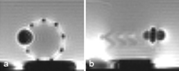
The stainless steel passive marker with its dimension presented in Sec. 2. 4 provides a distinct image artifact, visible as a dark spot with a diameter of about 10 mm (Fig. 7) and is used to indicate the orientation of the stented prosthesis at the time of implantation as well as after.
Fig. 7.
Image artifacts of the stainless steel marker on the stent under MRI. (a) Transversal section; (b) long axis section.
Because the contact of nitinol and stainless steel can result in corrosion if placed in a humid environment either an insulating layer between the stent and the marker is used or the entire assembly has to be coated with a protective coating.
It is well known that a metal stent creates a Faraday cage effect (it shields radio frequency signals) and makes the functionality of the bioprosthetic valve difficult to spot. The Faraday cage effect for the nitinol stent is less visible (Fig. 7) compared with platinum-iridium stent, for example.
3.2. In Vivo Experiment Results.
All ten large animals implanted with self-expanding stents and bioprostheses survived and were sacrificed per protocol at 6 months, then the hearts were harvested and histopathologically investigated.
rtMRI provided excellent visualization of the valve implantation with a self-expanding stent. In Fig. 8, three steps of the stented prosthesis deployment under MRI guidance are presented.
Fig. 8.

Self-expanding stented prosthesis deployment. (a) Stented prosthesis in delivery device, (b) stented prosthesis partially deployed, (c) stented prosthesis fully deployed.
The histopathology reports revealed that all the devices appeared to be properly seated in the aortic root, the stent is biocompatible, and fully functional. Both coronary ostia were widely patent and unobstructed by the stent frame or leaflets. The proximal end of the stent was well seated over the native valve annulus with no gaps noted between the stent frames, annulus, or aortic root. Distally, the stent was well opposed to the aortic wall and all strut tips appeared covered by neointimal growth.
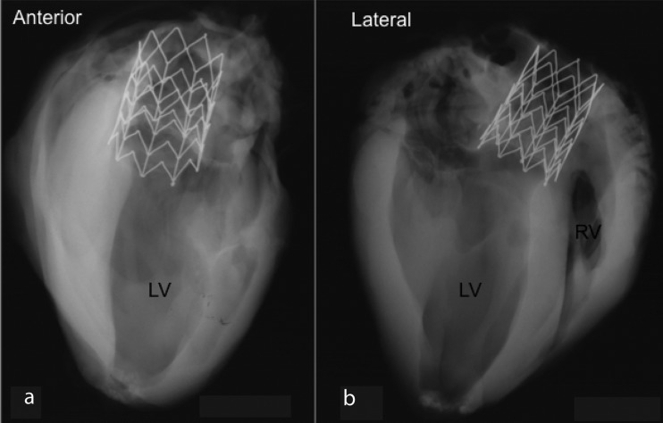
Radiographs of the heart taken from anterior and lateral aspects show a well-expanded frame in the aortic root. In Fig. 9 two radiographs of one specimen show an intact prosthetic valve stent frame without any fractures and mild tapering of the device from proximal to distal end.
Fig. 9.
Radiographs of the heart taken from anterior (a) and lateral (b)
At the proximal end of the device, the longitudinal struts were symmetrically expanded with all struts completely incorporated within neointimal growth. At the level distal to the prosthetic leaflets, the left and right coronary ostia were both widely patent and unobstructed by the commissure tips. However, stent struts are observed in the center of both ostia, but did not obstruct blood flow of either ostia and none were covered with neointimal tissue.
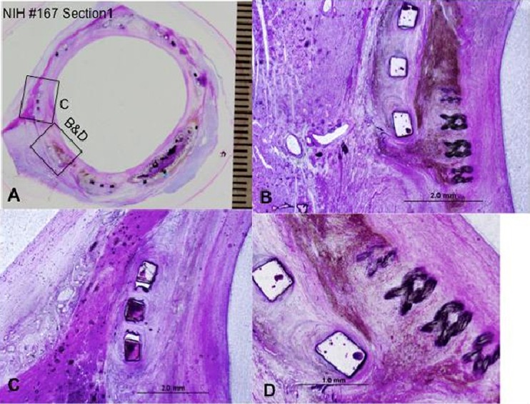
In Fig. 10(a) a whole mount view of a section at the proximal-most end of the device showing complete incorporation of the stent struts and focally where the skirt fabric (Dacron) bundles are presented; a high power view of the inferior edge of the device showing moderate chronic inflammation surrounding stent strut and adjacent skirt material and surrounding hemosiderin deposition (brown pigment) is presented in Fig. 10(b); and Fig. 10(c) presents higher magnification of a boxed area in 10(a) showing stent strut frame surrounded by a mild chronic inflammation and neointimal thickening with underlying right mitral valve trigone. Figure 10(d) presents higher magnification of the superficial region of the skirt fabric bundles and surrounding chronic inflammation and hemosiderin deposition.
Fig. 10.
The histopathology results at the proximal most end of the device. (a) Proximal section of the prosthetic valve; (b) high power view of the inferior edge of the device; (c) higher magnification of a boxed area in (a); (d) higher magnification of the superficial region of the skirt fabric bundles and surrounding chronic inflammation.
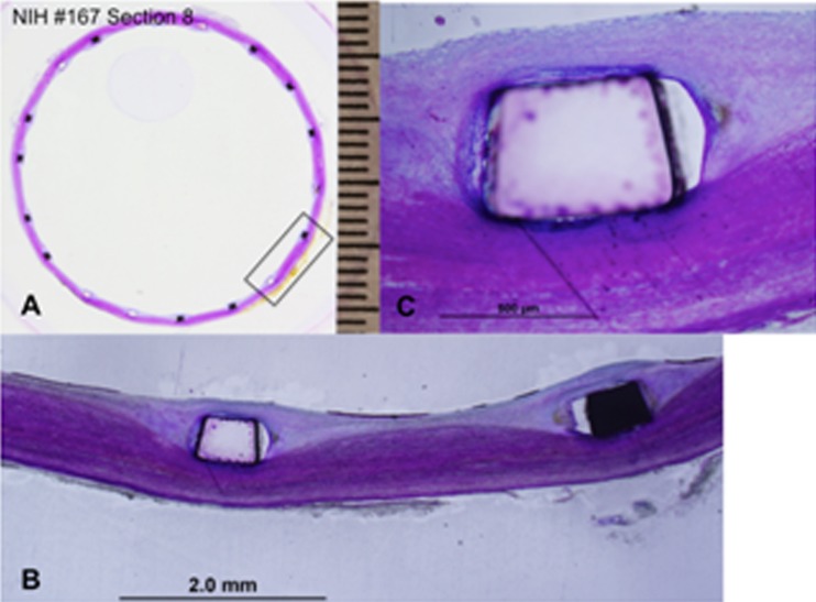
In Fig. 11(a), shows the most distal section of the prosthetic valve in aorta where only the stent frame is present and is surrounded by mild neointimal tissue which, completely covering the stent struts (Fig. 11(b)). Figure 11(c) is a high power view of the stent strut from Fig. 11(b) showing complete coverage of the stent strut by neointimal growth and surface endothelialization. The distal end of the stent was circular in shape with even apposition of the stent frame to the aortic wall and complete neointimal coverage of the stent struts with surface endothelialization and no peristrut inflammation. The aortic wall was free of luminal thrombus. The chronic inflammatory infiltration with surrounding neointima at the commissures and adjacent struts and skirt material is consistent with the normal healing processes.
Fig. 11.
The histopathology results at the most distal section of the prosthetic valve. (a) Distal section of the prosthetic valve; (b) mild neointimal tissue completely covering the stent struts; (c) is high power view of the stent strut from (b).
4. Discussion
Despite satisfying ex vivo and in vivo results in initial experiments, more stent design optimization and thorough stent/valve bench tests need to be conducted for future clinical application. Computational methods such as finite element method (FEM) play an important role in design optimization and evaluation of the mechanical properties of stents. The mechanical properties of the stents, especially radial force and fatigue depend on stents design parameters such as strut thickness, strut width, radius of curvature, stent geometry, stents material, and subsequent shape forming. In-depth FEM study of the stent design is necessary for evaluating the impact of design parameters on stent radial force and fatigue. Stress/strain analysis, combined with fatigue analysis of the stent, provides an indication of device durability. Accelerated durability testing of stents validates fatigue analysis and evaluates failure modes such as fretting, wear, and fracture. Also, durability testing can help in the identification of device conditions, such as manufacturing, shape forming, or material anomalies that are not previously modeled using analytical or computational methods. All the stents analyses and tests need to comply with Food and Drug Administration (FDA) recommendations for stents and associated delivery systems [34]. The durability of stent/replacement heart valves ensembles should be assessed using accelerated wear testing methods [35,36].
5. Conclusion
In this study, we proved that the custom designed self-expanding stent, a commercially available valve, and their associated delivery system are safe and reliable to be used for aortic valve replacement under rtMRI guidance.
The new self-expanding stent was designed to exert a constant radial force and therefore, better fixation of the prosthesis in the aorta, resulting in long-term preservation of normal valve and heart function.
The stent design consisting of nine longitudinal rods connected by chevron-shaped struts has three main advantages: prevents the stent from being dislodged by arterial pressure; allows the stent to be retracted in the delivery device; and allows the prosthetic valve to be compressed in the delivery device and deployed to the site without structural stress or damage. Also, the flared ends provide a better fixation of the stent to the implantation site.
The passive stainless steel marker aids precise orientation and positioning of the stent under MRI guidance.
The grasping members allow for the possibility of the stent to be retracted in the delivery device with a snare catheter.
Nitinol used for stent construction, presents several advantages: biocompatibility—shown by the histopathology report—and excellent corrosion resistance; good kink resistance—the stent can be completely compressed or crushed and will return to its original diameter when the acting force stops the interaction; and good MRI compatibility.
In vivo results show that all ten animals survived and the stented valves were properly seated in the aortic root. The histopathology reports confirm that the stent is biocompatible and the stented valve is fully functional. However, for clinical application, more research needs to be conducted. The next step is to work closely with the industry to further optimize the prosthesis, the delivery device, and the procedure overall.
Acknowledgment
The authors are supported through the Intramural Research Program of the National Heart, Lung, and Blood Institute, National Institutes of Health, United States Department of Health and Human Services (HHS). Also, the authors would like to thank Dr. Renu Virmani and Naima Carter-Monroe from CV Path Institute, Inc. for the pathology analysis.
Contributor Information
Dumitru Mazilu, e-mail: mazilud@nhlbi.nih.gov.
Ming Li, e-mail: lim2@nhlbi.nih.gov, Cardiothoracic Surgery Research Program, National Institutes of Health/National Heart, Lung, and Blood Institute, 10 Center Drive, MSC 1550, Bldg 10, Room B1D47, Bethesda, MD 20892 .
Ozgur Kocaturk, Cardiovascular Intervention Program, National Institutes of Health/National Heart, Lung, and Blood Institute, 10 Center Drive, MSC 1550, Bldg 10, Room B1D47, Bethesda, MD 20892 , e-mail: kocaturko@nhlbi.nih.gov.
Keith A. Horvath, Cardiothoracic Surgery Research Program, National Institutes of Health/National Heart, Lung, and Blood Institute, 10 Center Drive, MSC 1550, Bldg 10, Room B1D47, Bethesda, MD 20892, e-mail: horvathka@nhlbi.nih.gov
References
- [1]. Leon, M. B. , Smith, C. R. , Mack, M. , Miller, D. C. , Moses, J. W. , Svensson, L. G. , Tuzcu, E. M. , Webb, J. G. , Fontana, G. P. , Makkar, R. R. , Brown, D. L. , Block, P. C. , Guyton, R. A. , Pichard, A. D. , Bavaria, J. E. , Herrmann, H. C. , Douglas, P. S. , Petersen, J. L. , Akin, J. J. , Anderson, W. N. , Wang, D. , and Pocock, S. , 2010, “Transcatheter Aortic-Valve Implantation for Aortic Stenosis in Patients Who Cannot Undergo Surgery,” N. Engl. J. Med., 363(17), pp. 1597–160710.1056/NEJMoa1008232 [DOI] [PubMed] [Google Scholar]
- [2]. Walther, T. , Möllmann, H. , Blumenstein, J. , and Kempfert, J. , 2011, “Transcatheter Aortic Valve Implantation for Severe Aortic Stenosis—Overcoming the Challenges,” Interv. Cardiol., 6(2), pp. 165–169, available at http://www.touchbriefings.com/ebooks/A1tts5/Intcardio62/resources/71.htm [Google Scholar]
- [3]. Cribier, A. , 2012, “Development of Transcatheter Aortic Valve Implantation (TAVI): A 20-Year Odyssey,” Arch. Cardiovasc. Dis., 105(3), pp. 146–152 10.1016/j.acvd.2012.01.005 [DOI] [PubMed] [Google Scholar]
- [4]. Cribier, A. , Eltchaninoff, H. , Bash, A. , Borenstein, N. , Tron, C. , Bauer, F. , Derumeaux, G. , Anselme, F. , Laborde, F. , and Leon, M. B. , 2002, “Percutaneous Transcatheter Implantation of an Aortic Valve Prosthesis for Calcific Aortic Stenosis. First Human Case Description,” Circulation, 106, pp. 3006–300810.1161/01.CIR.0000047200.36165.B8 [DOI] [PubMed] [Google Scholar]
- [5]. Walther, T. , Simon, P. , Dewey, T. , Wimmer-Greinecker, G. , Falk, V. , Kasimir, M. T. , Doss, M. , Borger, M. A. , Schuler, G. , Glogar, D. , Fehske, W. , Wolner, E. , Mohr, F. W. , and Mack, M. , 2007, “Transapical Minimally Invasive Aortic Valve Implantation: Multicenter Experience,” Circulation, 116(11_suppl), pp. I-240–24510.1161/CIRCULATIONAHA.106.677237 [DOI] [PubMed] [Google Scholar]
- [6]. Chiam, P. T. L. , and Ruiz, C. E. , 2008, “Percutaneous Transcatheter Aortic Valve Implantation: Assessing Results, Judging Outcomes, and Planning Trials: The Interventionalist Perspective,” JACC: Cardiovasc. Interv., 1(4), pp. 341–35010.1016/j.jcin.2008.03.018 [DOI] [PubMed] [Google Scholar]
- [7]. Lichtenstein, S. V. , Cheung, A. , Ye, J. , Thompson, C. R. , Carere, R. G. , Pasupati, S. , and Webb, J. G. , 2006, “Transapical Transcatheter Aortic Valve Implantation in Humans Initial Clinical Experience,” Circulation, 114, pp. 591–59610.1161/CIRCULATIONAHA.106.632927 [DOI] [PubMed] [Google Scholar]
- [8]. Thomas, M. , Schymik, G. , Walther, T. , Himbert, D. , Lefèvre, T. , Treede, H. , Eggebrecht, H. , Rubino, P. , Michev, I. , Lange, R. , Anderson, W. N. , and Wendler, O. , 2010, “Thirty-Day Results of the SAPIEN Aortic Bioprosthesis European Outcome (SOURCE) Registry,” Circulation, 122(1), pp. 62–69 10.1161/CIRCULATIONAHA.109.907402 [DOI] [PubMed] [Google Scholar]
- [9]. Grube, E. , Schuler, G. , Buellesfeld, L. , Gerckens, U. , Linke, A. , Wenaweser, P. , Sauren, B. , Mohr, F.-W. , Walther, T. , Zickmann, B. , Iversen, S. , Felderhoff, T. , Cartier, R. , and Bonan, R. , 2007, “Percutaneous Aortic Valve Replacement for Severe Aortic Stenosis in High-Risk Patients Using the Second- and Current Third-Generation Self-Expanding CoreValve Prosthesis: Device Success and 30-Day Clinical Outcome,” J. Am. Coll. Cardiol., 50(1), pp. 69–7610.1016/j.jacc.2007.04.047 [DOI] [PubMed] [Google Scholar]
- [10]. Lamarche, Y. , Cartier, R. , Denault, A. Y. , Basmadjian, A. , Berry, C. , Laborde, J.-C. , and Bonan, R. , 2007, “Implantation of the CoreValve Percutaneous Aortic Valve,” Ann. Thorac. Surg., 83(1), pp. 284–28710.1016/j.athoracsur.2006.05.121 [DOI] [PubMed] [Google Scholar]
- [11]. Grube, E. , Laborde, J. C. , Gerckens, U. , Felderhoff, T. , Sauren, B. , Buellesfeld, L. , Mueller, R. , Menichelli, M. , Schmidt, T. , Zickmann, B. , Iversen, S. , and Stone, G. W. , 2006, “Percutaneous Implantation of the CoreValve Self-Expanding Valve Prosthesis in High-Risk Patients With Aortic Valve Disease: The Siegburg First-in-Man Study,” Circulation, 114, pp. 1616–162410.1161/CIRCULATIONAHA.106.639450 [DOI] [PubMed] [Google Scholar]
- [12]. Petronio, A. S. , De Carlo, M. , Bedogni, F. , Marzocchi, A. , Klugmann, S. , Maisano, F. , Ramondo, A. , Ussia, G. P. , Ettori, F. , Poli, A. , Brambilla, N. , Saia, F. , De Marco, F. , and Colombo, A. , 2011, “Safety and Efficacy of the Subclavian Approach for Transcatheter Aortic Valve Implantation With the CoreValve Revalving System/Clinical Perspective,” Circulation: Cardiovascular Interventions, 3(4), pp. 359–36610.1161/CIRCINTERVENTIONS.109.930453 [DOI] [PubMed] [Google Scholar]
- [13]. Falk, V. , Walther, T. , Schwammenthal, E. , Strauch, J. , Aicher, D. , Wahlers, T. , Schäfers, J. , Linke, A. , and Mohr, F. W. , 2011, “Transapical Aortic Valve Implantation With a Self-Expanding Anatomically Oriented Valve,” Eur. Heart J., 32(7), pp. 878–887 10.1093/eurheartj/ehq445 [DOI] [PubMed] [Google Scholar]
- [14]. Ferrari, M. , Figulla, H. R. , Schlosser, M. , Tenner, I. , Frerichs, I. , Damm, C. , Guyenot, V. , Werner, G. S. , and Hellige, G. , 2004, “Transarterial Aortic Valve Replacement With a Self Expanding Stent in Pigs,” Heart, 90, pp. 1326–133110.1136/hrt.2003.028951 [DOI] [PMC free article] [PubMed] [Google Scholar]
- [15]. Kempfert, J. , Holzhey, D. , Rastan, A. , Schoenburg, M. , Treede, H. , Thielmann, M. , van Linden, A. , Njezic, B. , Blumenstein, J. , Mohr, F. W. , and Wather., T. , 2011, “Transapical Aortic Valve Implantation Using the Symetis Accurate™ Device: Initial Clinical Experience,” 25th Annual Meeting of the European Association for Cardio-Thoracic Surgery (EACTS), Lisbon, Portugal, October 1–5. [Google Scholar]
- [16]. Boudjemline, Y. , and Bonhoeffer, P. , 2002, “Steps Toward Percutaneous Aortic Valve Replacement,” Circulation, 105, pp. 775–77810.1161/hc0602.103361 [DOI] [PubMed] [Google Scholar]
- [17]. McVeigh, R. E. , Guttman, A. M. , Lederman, J. R. , Li, M. , Kocaturk, O. , Hunt, T. , Kozlov, S. , and Horvath, A. K. , 2006, “Real-Time Interactive MRI-Guided Cardiac Surgery: Aortic Valve Replacement Using a Direct Apical Approach,” Magn. Reson. Med., 56(5), pp. 958–96410.1002/mrm.21044 [DOI] [PMC free article] [PubMed] [Google Scholar]
- [18]. Cribier, A. , Eltchaninoff, H. , Tron, C. , Bauer, F. , Agatiello, C. , Nercolini, D. , Tapiero, S. , Litzler, P.-Y. , Bessou, J.-P. , and Babaliaros, V. , 2006, “Treatment of Calcific Aortic Stenosis With the Percutaneous Heart Valve: Mid-Term Follow-Up From the Initial Feasibility Studies: The French Experience,” J. Am. Coll. Cardiol., 47(6), pp. 1214–122310.1016/j.jacc.2006.01.049 [DOI] [PubMed] [Google Scholar]
- [19]. Dewey, T. M. , Walther, T. , Doss, M. , Brown, D. , Ryan, W. H. , Svensson, L. , Mihaljevic, T. , Hambrecht, R. , Schuler, G. , Wimmer-Greinecker, G. , Mohr, F. W. , and Mack, M. J. , 2006, “Transapical Aortic Valve Implantation: An Animal Feasibility Study,” Ann. Thorac. Surg., 82(1), pp. 110–11610.1016/j.athoracsur.2006.02.035 [DOI] [PubMed] [Google Scholar]
- [20]. Horvath, K. A. , Guttman, M. , Li, M. , Lederman, R. J. , Mazilu, D. , Kocaturk, O. , Karmarkar, P. V. , Hunt, T. , Kozlov, S. , and McVeigh, E. R. , 2007, “Beating Heart Aortic Valve Replacement Using Real-Time MRI Guidance,” Innovations, 2(2), pp. 51–5510.1097/IMI.0b013e31805b8280 [DOI] [PubMed] [Google Scholar]
- [21]. Huber, C. H. , Cohn, L. H. , and von Segesser, L. K. , 2005, “Direct-Access Valve Replacement a Novel Approach for Off-Pump Valve Implantation Using Valved Stents,” J. Am. Coll. Cardiol., 46(2), pp. 366–37010.1016/j.jacc.2005.04.028 [DOI] [PubMed] [Google Scholar]
- [22]. Webb, J. , and Cribier, A. , 2011, “Percutaneous Transarterial Aortic Valve Implantation: What Do We Know?,” Eur. Heart J., 32(2), pp. 140–14710.1093/eurheartj/ehq453 [DOI] [PubMed] [Google Scholar]
- [23]. Webb, J. G. , Pasupati, S. , Humphries, K. , Thompson, C. , Altwegg, L. , Moss, R. , Sinhal, A. , Carere, R. G. , Munt, B. , Ricci, D. , Ye, J. , Cheung, A. , and Lichtenstein, S. V. , 2007, “Percutaneous Transarterial Aortic Valve Replacement in Selected High-Risk Patients With Aortic Stenosis,” Circulation, 116(7), pp. 755–76310.1161/CIRCULATIONAHA.107.698258 [DOI] [PubMed] [Google Scholar]
- [24]. Walther, T. , Falk, V. , Borger, M. A. , Dewey, T. , Wimmer-Greinecker, G. , Schuler, G. , Mack, M. , and Mohr, F. W. , 2007, “Minimally Invasive Transapical Beating Heart Aortic Valve Implantation—Proof of Concept,” Eur. J. Cardiothorac. Surg., 31(1), pp. 9–1510.1016/j.ejcts.2006.10.034 [DOI] [PubMed] [Google Scholar]
- [25]. Duerig, T. W. , Tolomeo, D. E. , and Wholey, M. , 2000, “An Overview of Superelastic Stent Design,” Min. Invas. Ther. Allied Technol., 9(3/4), pp. 235–24610.1080/13645700009169654 [DOI] [PubMed] [Google Scholar]
- [26]. Stoeckel, D. , Pelton, A. , and Duerig, T. , 2004, “Self-Expanding Nitinol Stents: Material and Design Considerations,” Eur. Radiol., 14(2), pp. 292–30110.1007/s00330-003-2022-5 [DOI] [PubMed] [Google Scholar]
- [27]. David, A. , and Armitage, T. L. P. D. M. G. , 2003, “Biocompatibility and Hemocompatibility of Surface-Modified NiTi Alloys,” J. Biomed. Mater. Res. A, 66A(1), pp. 129–13710.1002/jbm.a.10549 [DOI] [PubMed] [Google Scholar]
- [28]. Vojtech, D. , Joska, L. , and Leitner, J. , 2008, “Influence of a Controlled Oxidation at Moderate Temperatures on the Surface Chemistry of Nitinol Wire,” Appl. Surf. Sci., 254(18), pp. 5664–5669 10.1016/j.apsusc.2008.03.014 [Google Scholar]
- [29]. Wever, D. J. , Veldhuizen, A. G. , Sanders, M. M. , Schakenraad, J. M. , and van Horn, J. R. , 1997, “Cytotoxic, Allergic and Genotoxic Activity of a Nickel-Titanium Alloy,” Biomaterials, 18(16), pp. 1115–112010.1016/S0142-9612(97)00041-0 [DOI] [PubMed] [Google Scholar]
- [30]. Yeung, K. W. K. , Poon, R. W. Y. , Liu, X. Y. , Ho, J. P. Y. , Chung, C. Y. , Chu, P. K. , Lu, W. W. , Chan, D. , and Cheung, K. M. C. , 2005, “Corrosion Resistance, Surface Mechanical Properties, and Cytocompatibility of Plasma Immersion Ion Implantation-Treated Nickel-Titanium Shape Memory Alloys,” J. Biomed. Mater. Res. A, 75A(2), pp. 256–26710.1002/jbm.a.30413 [DOI] [PubMed] [Google Scholar]
- [31]. Horvath, K. A. , Mazilu, D. , Guttman, M. , Zetts, A. , Hunt, T. , and Li, M. , 2010, “Midterm Results of Transapical Aortic Valve Replacement via Real-Time Magnetic Resonance Imaging Guidance,” J. Thorac. Cardiovasc. Surg., 139(2), pp. 424–43010.1016/j.jtcvs.2009.08.005 [DOI] [PMC free article] [PubMed] [Google Scholar]
- [32]. Horvath, A. K. , Li, M. , Mazilu, D. , Guttman, A. M. , and McVeigh, E., R. , 2007, “Real-Time Magnetic Resonance Imaging Guidance for Cardiovascular Procedures,” Semin. Thor. Cardiovasc. Surg., 19(4), pp. 330–33510.1053/j.semtcvs.2007.10.006 [DOI] [PMC free article] [PubMed] [Google Scholar]
- [33]. Horvath, A. K. , Mazilu, D. , Guttman, A. M. , and Li, M. , 2009, “Beating Heart Aortic Valve Replacement Under Real Time MRI Guidance,” J. Surg. Res., 151(2), pp. 225–22610.1016/j.jss.2008.11.132 [DOI] [PubMed] [Google Scholar]
- [34].2010, “Guidance for Industry and FDA Staff—Non-Clinical Engineering Tests and Recommended Labeling for Intravascular Stents and Associated Delivery Systems,” Federal Register. U.S. Food and Drug Administration, Silver Spring, MD, available at http://www.fda.gov/medicaldevices/deviceregulationandguidance/guidancedocuments/ucm071863.htm
- [35].2005, “Cardiovascular Implants—Cardiac Valve Prostheses,” ISO 5840:2005, Federal Register. U.S. Food and Drug Administration, Silver Spring, MD, available at http://www.fda.gov/medicaldevices/deviceregulationandguidance/guidancedocuments/ucm193096.htm
- [36].2010, “Draft Guidance for Industry and FDA Staff—Heart Valves—Investigational Device Exemption (IDE) and Premarket Approval (PMA) Applications,” ISO (International Organization for Standardization), Geneva, Switzerland, available at http://www.iso.org/iso/catalogue_detail.htm?csnumber=34164


