Abstract
Stem cells niches are increasingly recognized as dynamic environments that play a key role in transducing signals that allow an organism to exert control on its stem cells. Live imaging of stem cell niches in their in vivo setting is thus of high interest to dissect stem cell controls. Here we report a new microfluidic design that is highly amenable to dissemination in biology laboratories that have no microfluidics expertise. This design has allowed us to perform the first time lapse imaging of the C. elegans germline stem cell niche. Our results show that this niche is strikingly dynamic, and that morphological changes that take place during development are the result of a highly active process. These results lay the foundation for future studies to dissect molecular mechanisms by which stem cell niche morphology is modulated, and by which niche morphology controls stem cell behavior.
Introduction
Regulation of fundamental stem cell behaviors — cycling and self-renewal — is a topic of high interest for understanding development and for making therapeutic use of stem cells. Stem cells are found in niches, whose makeup varies between organs and species1. The crucial role of these niches in stem cell maintenance is well established (e.g. 2), but the sophistication of stem cell regulation goes well beyond controlling their numbers by delimiting a fixed volume in which they can exist. Numerous lines of evidence suggest stem cell niches to be dynamic environments that allow for control not only of stem cell number3, but also of the behavior of stem cells and their descendants4 — perhaps in a way that allows for tight coordination between various stem cell types5, and that allows for control by the nervous system6. Characterizing niche dynamics will thus be a key step in dissecting in vivo extrinsic controls of stem cells and their descendants.
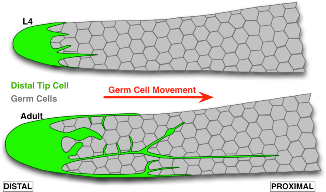
The C. elegans germline stem cell niche is a powerful model system to study niche dynamics. Indeed, this niche is well defined and can be imaged live in intact animals. It is made of a single somatic cell, the distal tip cell (DTC), which acts as a niche at least in part by presenting germline stem cells with Notch ligands. The DTC is located at the distal end of the gonadal arm, which essentially forms a tube of germ cells that are displaced in a distal to proximal direction as they proceed through differentiation (Fig. 1). Notch signaling in germ cells is required for maintenance of stem cells and the mitotic zone, as shown by premature germ cell differentiation when the DTC is ablated2 or when the Notch receptor is genetically inactivated7. As hermaphroditic larvae go through the last larval stage L4 and enter adulthood, the DTC extends striking long filopodia-like structures called “processes” that carry at least one Notch ligand8–10. The precise role of these processes remains unaddressed, but their similarity with structures found in other species and other organs11 strongly suggests that they are of functional significance.
Figure 1.
The C. elegans gonad forms a tube that is closed at the distal end, where stem cells are located, and open at the proximal end (not shown) from which differentiated gametes exit. The Distal Tip Cell (DTC) acts as a stem niche, at least in part by expressing Notch ligands. The DTC extends processes that start growing from the last larval stage (L4). These processes tightly intercalate between germ cells, especially in the distal region where stem cells are located, and in mature adults extend past the mitotic zone in which cells are proliferating.
The C. elegans germline stem cell niche is furthermore a relevant model system to study interactions between niches and their host organism. Indeed, expression of Notch ligand by the DTC has been shown to be regulated by extrinsic TGF-beta signaling, possibly under neuronal control12,13. DTC morphology is also altered during adult reproductive diapause14, suggesting a potential mechanism by which a small pool of stem cells is kept in a quiescent state for future regeneration. Control of Notch ligand levels on DTC processes and control of DTC process morphology could thus provide for coordination between germline stem cells and the rest of the organism.
But despite the high relevance of the DTC as a model dynamic stem cell niche and despite its striking morphology, little is known about the dynamics of its morphology. Although it is known that the processes start extending when hermaphrodites reach adulthood and continue doing so over the course of at least 3 days10, it is not known whether this extension is the result of active DTC growth, or merely the result of DTC membrane being passively dragged by proliferating germ cells as they are being displaced in a distal to proximal direction. Arguing for the latter is the adhesion often observed between stem cells and their niches15, the close association of the DTC with the distal-most germ cells9,10, and the apparent internalization of DTC content by germ cells16. Arguing for active growth is that the extension of DTC processes takes place in hermaphrodites but not in males17, at a specific stage of development. Resolving this question would be an important first step in addressing the role of DTC morphology as a control of germline stem cells.
The lack of current data on DTC morphology results in large part from limitations in tools to perform minimally-disruptive live imaging of C. elegans. Imaging of fixed samples only makes it possible to study population-level behavior; stochasticity and variability between individuals can mask dynamics, especially on a short time scale. Live imaging can be performed with permanent immobilization of worms, but such immobilization results in strong defects in germ cell proliferation (our unpublished observations). While methods exist to reversibly immobilize worms, they carry biological or technical drawbacks. Biological drawbacks include non-immediate recovery or other perturbation of animal physiology (as for anesthesia18, reversible cooling19, or exposure to CO220), or repetitive transfers of worms that can lead to damage (as for agarose bead immobilization21). Technical drawbacks exist for methods that rely on worm confinement based on deformable membranes, suction channels or tapered channels22–24, or are based on temperature-controlled transition of pluronic acid between liquid and gel phases25. These devices are based on complex, multi-layered microfluidic designs that require specialized equipment and expertise to build, and/or external pneumatic, hydraulic, or temperature control systems that also require specialized expertise to use. We thus designed a simple device, the manufacture and use of which are accessible to biology labs with no ad-hoc technical expertise. This device allowed us to reversibly immobilize worms under nearlyphysiological conditions, and to characterize the dynamics of DTC processes over short time intervals in individual worms.
Results
Device design and fabrication
Construction of microfluidic devices typically requires specialized equipment and training to perform photolithographic patterning and lamination of channels and actuated structures. Devices for C. elegans manipulation can require even greater complexity than is typical. For example, a nonstandard photoresist that is thick and capable of thermal reflow is required to form rounded channels that are both compatible with pneumatic valves and large enough to fit worms.22 This resist is very costly in comparison to standard photoresists. Actuation of on-chip components also requires a complex network of pneumatic tubing and computer-controlled solenoid valves, and in some cases, the piping of hot and cool liquids onto the chip.25 Here, we achieve large rounded channels simply by molding off of pencil leads in a very low-cost process. Further, device actuation is achieved simply by pressing on the structure.
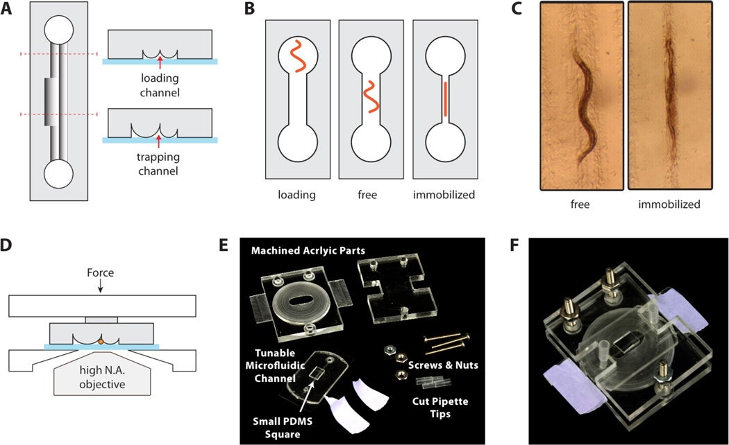
The core of the immobilization device is a microfluidic channel that can be tuned in diameter. The channel cross section is roughly triangular and is formed by sealing an elastomeric stamp with cylindrical ridges against a No. 2 glass coverslip (Fig. 2A). Downward compression on the elastomer collapses the cylindrical ridges against the glass, thus narrowing the channel. The dimensions of the channel were designed such that a young adult worm could move freely in an uncompressed channel and be immobilized in a compressed channel (Fig. 2B–C, Movie 1). The channel was designed to be narrower towards the inlet and outlet so that by partially compressing the device, a non-immobilized worm could be confined to the center of the device in order to keep it from drifting out of the microscope field of view. Individual worms were loaded through access ports punched at either end of the channel, and vacuum aspiration was used to draw the worm into the channel. Cut pipette tips were inserted into the access ports to serve as liquid reservoirs, and continuous flow could be maintained in the channel by asymmetric loading of the two reservoirs. Controlled compression of the device was accomplished by using a clamping structure machined in poly (methyl methacrylate) (Fig. 2D–F). Full engineering drawings are provided in the online supplemental material (Fig. S2). The bottom of the clamping structure tapers to a small oval hole to allow high-resolution microscope objectives to approach the sample while minimizing bending of the coverslip during compression. The structure was held together by three sets of nuts and screws, and compression was adjusted by turning the nuts while observing worm mobility under a microscope.
Figure 2.
Worm immobilization device. (A) Cross sections. A tunable-diameter microfluidic channel is formed by sealing an elastomer with cylindrical ridges onto a glass coverslip. The loading channels are narrower than the worm-trapping region to confine the worm in the middle of the device. (B) A worm is placed into one of the access ports and loaded by aspiration. The device is compressed to constrict the channel and immobilize the worm. (C) Microscope images of a worm in the device. An adult worm can be cultured for hours in an uncompressed channel and reversibly immobilized for imaging at specific time points. (D) An acrylic clamping rig maintains compression of the elastomer against the glass, while allowing microscope access for imaging through the coverslip. (E) The clamping rig includes slats to facilitate mounting on a microscope stage. A PDMS square (6 × 3 × 2 mm3) is placed over the microchannels to focus the compression force. (F) Assembled device.
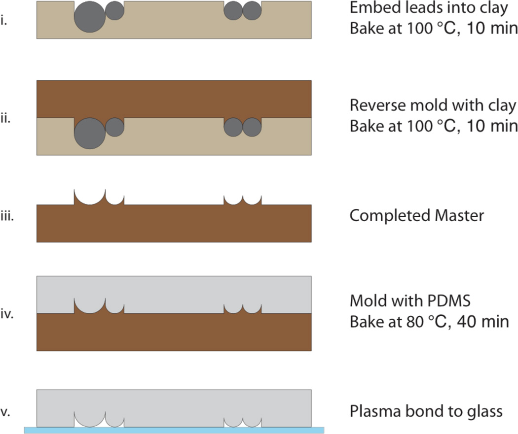
Fabrication of the elastomeric microchannels was accomplished without the need for any specialized equipment. As detailed in Fig. 3, a mold was created from sculpting clay (Original Sculpey Clay, Polyform Products, Elk Grove Village, IL) and 0.3 mm and 0.5 mm leads (Pentel, Torrance, CA) typically used in mechanical pencils. The leads were embedded into the clay in pairs and pressed down under a glass slide until the tops of the leads were flush with the surface of the clay. This structure was baked at 100°C for 10 min and then used as a mold to cast a second piece of clay. The surface of the mold was wet with a small amount of water prior to casting in order to prevent sticking. The second piece of clay, the inverse of the first mold, was also baked at 100°C for 10 min and then used as a master to cast polydimethylsiloxane (PDMS) stamps. PDMS casting was accomplished by thoroughly mixing prepolymer and linker (Sylgard 184, Dow Corning, Midland, MI) at 15:1 by weight, pouring this mixture over the clay mold, degassing in a vacuum chamber, and baking at 80°C for 40 minutes. Access holes were created in the molded PDMS stamps by using a 3 mm biopsy punch, and the stamps were then plasma bonded (2 min, ambient gas) to glass coverslips to create tunable microchannels. Plasma bonding was helpful to eliminate the possibility for worms to slide into parallel channels. However, bonding was not absolutely essential as long as the PDMS stamp remained pressed against the glass.
Figure 3.
Device fabrication process. (i) 0.5 mm and 0.3 mm mechanical pencil leads are pressed into molding clay until the tops of the cylinders are flush with the clay surface, and the entire structure is baked. The use of a wider lead results in a larger channel diameter in the completed device. (ii) Additional sculpting clay is pressed into the baked structure. (iii) The reverse-molded clay is baked to form the master mold. (iv) The master is used to cast a PDMS stamp. (v) Access holes are created in the PDMS by using a 3-mm biopsy punch, and the PDMS stamp is attached to a glass coverslip by plasma bonding.
Device validation
We first assayed the impact of worm immobilization and imaging on germ cell cycling and on reproductive activity. We immobilized and acquired 0.2µm-interval confocal stacks of young adult hermaphrodites 9 times at one-hour intervals; each individual was imaged in less than 2 minutes. Controls were incubated in culture medium identical to that of imaged worms, but were kept in 24-well plates rather than in our device and were not immobilized or imaged. After 9 hours, imaged and control worms were each split into two groups. One group had gonads stained for DNA and phosphorylated histone H3 to assay mitotic index, and another group was returned to agar plates to score reproductive output.
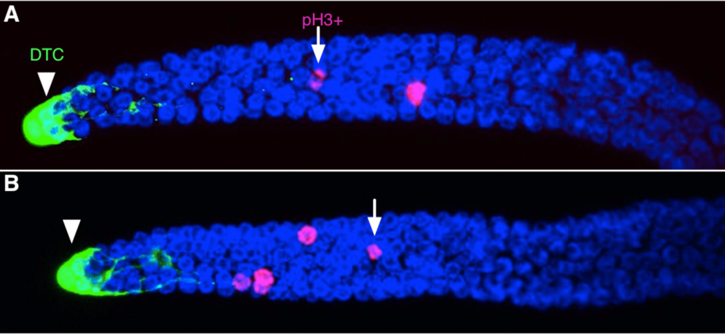
Overall gonad morphology of imaged and control worms was indistinguishable (Fig. 4). Average mitotic index was 3.0 for imaged worms (n=11), and 3.5 for control worms (n=11). This ~15% difference was not significant (p>0.33) and both values fall within the range of previous reports (e.g.26,10), which suggests that germ cell cycling is not appreciably perturbed by immobilization or imaging.
Figure 4.
Gonadal arms extruded, fixed, and stained with antibodies and DAPI show indistinguishable morphology whether they were repeatedly immobilized and imaged live (A) or kept in identical liquid culture medium without immobilization or live imaging (B). The DTC is shown with an arrowhead, and examples of pH3-positive cells with arrows. Images shown are standard deviation projections of confocal stacks.
Average number of progeny was 170 for imaged worms (n=9), and 248 for control worms (n=21). The difference — 30% — is modest and not statistically significant (p>0.11). Furthermore, this difference stems specifically from 3 imaged specimens that died within 3 days of imaging; when excluding specimens that died within the first 3 days after imaging, average progeny number is 247 (n=6) and is indistinguishable from the control average of 259 progeny (n=20; p>0.6; 1/21 control died within 6 days). We thus conclude that immobilization and imaging in our device do not appreciably affect reproductive output.
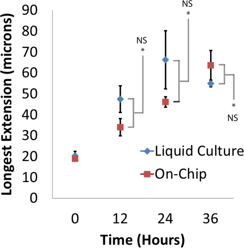
We next asked whether the dynamics of DTC process extension were affected by hermaphrodite immobilization and imaging. We compared DTC growth in single worms that were immobilized and imaged at multiple time points, against average DTC growth in worms maintained in standard liquid culture and sacrificed for imaging at a single time point (Fig. 5). Worms in the device and control worms were all in S medium supplemented with E. coli. No significant difference was observed in the length of the longest DTC process over 4 rounds of immobilization spanning 36 hours (p>0.05 with t-test; n=7).
Figure 5.
DTC process extension is not detectably affected by repeated immobilization in the device. Liquid culture: hermaphrodites were cultured for the specified amount of time in S-medium supplemented with E. coli, and permanently immobilized with polystyrene beads for imaging at the time indicated. On chip: worms were kept in the device and temporarily immobilized for live imaging of processes at each indicated time point.
Device reveals dynamics that are obscured in population averages
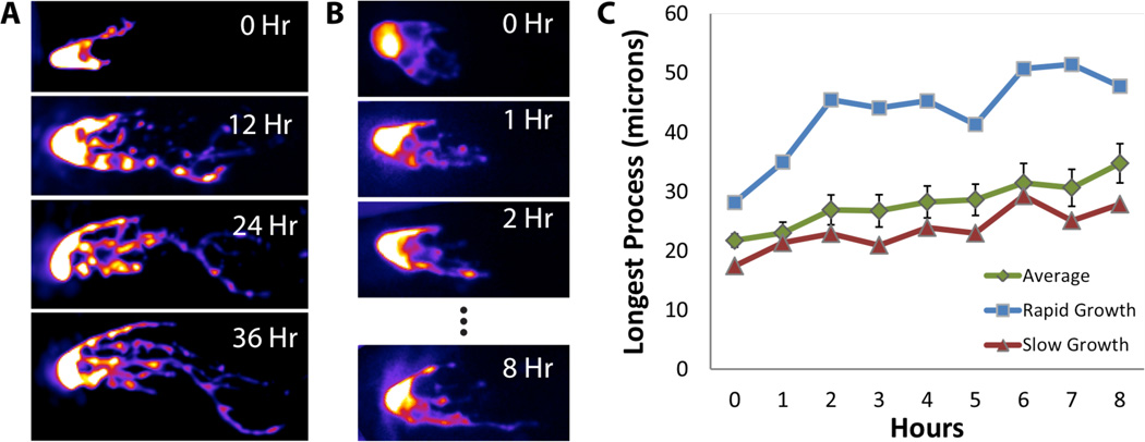
To ask whether the dynamics of DTC growth are uniform across time and individuals, we imaged the DTC at 1-hour intervals from L4. While the population average of length of the longest DTC process progressed linearly, striking variability was apparent between individuals. Some experienced slow growth, while others experienced rapid growth (Fig. 6). The difference in growth rates could be attributable to slight differences in developmental stages of the individuals in the population. In any case, imaging individuals through time reveals that the population average is not representative of individual behavior. Furthermore, spurts of growth observed in fast-growing DTCs suggested the possibility of an active growth mechanism rather than passive DTC stretching over time.
Figure 6.
Time lapse imaging of the DTC at long (12 h) or short (1 h) intervals reveals growth of individual processes. Dynamics of growth differ between individuals. While average growth is close to linear (green curve in C), some DTCs experience apparent spurts of growth (blue curve in C) while others experience more even, slow growth (red curve in C).
Local remodeling, backwards growth, and branch points
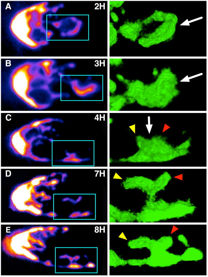
We next asked what local shape changes underlie the overall lengthening of the DTC. We tracked individual DTCs through time at 1-hour intervals. We made three striking observations. First, process elongation can take place following two distinct steps: a process first forms a ring, which subsequently regains a linear topology (Fig. 7A). Second, growing processes can form branch points that give rise to multiple small nascent extensions (Fig. 7C; Fig. S1); after a period of time, a single extension appears to grow further while others retreat, suggesting potential competition between nascent extensions (Fig. 7C to 7E). Third, process elongation can take place not only along the direction of overall DTC growth (from distal to proximal), but also in the reverse direction (Fig. 7D). Branch points with multiple nascent extensions or backward growth of processes were observed in 5 of 10 samples (see Fig. S1 for another example).
Figure 7.
Time lapse imaging of DTC processes shows an active growth and infiltration of the mitotic region (left: confocal section; right: ray tracing rendering of region boxed on left). Two important features emerge. First, some processes extend proximally by forming a transient ring-like structure (arrow on row A) that subsequently regains a linear topology (arrow on row B). Second, some processes form a bulb-like structure (arrow on row C) that changes shape over time and results in distal and thus “backward” growth of an extension (yellow arrow heads in C–E). Such extensions appear to tightly intercalate between germ cells. Another extension shows more limited growth (red arrowheads). Confocal stacks of each time point in this dataset are available in the Electronic Supplementary Information.
Discussion
Our observations of DTC processes over time strongly suggest that their growth is an active process. The transient ring structure that we observe during process elongation shows that processes are not simply stretched by a pulling force generated by germ cell migration along the distal to proximal axis. A ring structure similar to what we observed has been reported by electron microscopy9, lending evidence that our ring is not an artifact (due for example to a very thin central layer that does not contain a detectable amount of cytoplasmic GFP).
The branch points with nascent extensions suggest that the DTC could be actively exploring the environment formed by germ cells. The fact that in some instances only one of these extensions appears to persist and grow suggests possible competition between processes. Biases in the outcome of that competition could result from local signaling between DTC processes and germ cells, perhaps transduced by changes in membrane tension27,28. An important question to address in future experiments will be whether DTC processes actually do respond to germ cell state, and thus whether there is feedback from germline stem cells to their niche.
Our results suggest that the C. elegans germline stem cell niche is a dynamic entity that actively seeks contact with a subset of proliferating germ cells. Active movement of the stem cell niche has been observed in the Drosophila ovary29 (this movement does not result in net migration); human hematopoietic stem cells also have a dynamic, elaborate contact surface with osteoblasts that plays a role in polarization30. Dynamic control of the contact surface between stem cells and their niche could thus be a general feature of stem cell systems. The C. elegans germline, when imaged live with a device such as the one we report here, provides a powerful model system to address this dynamic control: the niche can be imaged in its native environment, and the relationship between niche and stem cells dissected with genetic tools.
An important question to address in the future will be the functional significance of the spatial pattern of contact between cycling cells and the DTC, which is established by the infiltration process reported here. A role of the DTC in controlling the length of the mitotic zone has long been suspected31,8,9, but the shortening of the mitotic zone in aging worms despite concomitant DTC process lengthening could be at odds with this idea10. One possibility is that DTC spatial patterns contribute to the control of transitions between differentiation states identified more recently within the mitotic zone32.
Materials and Methods
Worm handling
The strain used was JK2868 (qIs56[lag-2::gfp] V)33, which was maintained at 20°C outside of the microfluidic device as described34 using E. coli HB101 as a food source. Looselysynchronized populations were obtained by isolating young adults from unsynchronized populations; devices were loaded with descendants that were at the L4 stage (as identified by visual inspection of vulval shape) at the desired time. The microfluidic device was operated with S medium35 supplemented with E. coli HB101 concentrated to 109—1010/mL; constant gravity flow of the medium through the device guarded against local depletion of bacteria. During time course imaging, worms were immobilized for a maximum of 2 minutes at each time point. In between time points, the channels were expanded by releasing compression, allowing the worms to move freely. Both pharynx pumping and head foraging movements were observed in released worms. We did not assay whether worms actively feed during the short periods of immobilization, but normal reproductive output, mitotic index, and DTC growth suggest that potential nutrient deprivation during immobilization is not detrimental.
Gonad extrusion and staining were performed as described36. Mitotic index was computed as the ratio of pH3-positive cells to the total number of cells counted in the mitotic zone. Live imaging of permanently-immobilized worms reported in Fig. 5 was performed using agarose and polystyrene beads21.
Progeny counts
Hermaphrodites were passaged every day to fresh plates, until the end of reproductive activity. Plates on which embryos had been laid were incubated for ~2 days to let progeny hatch and grow in size; progeny were counted before they reached the adult stage. Mothers that crawled off agar (n=3) were censored from the analysis.
Imaging
Images were acquired on a Zeiss Cell Observer SD spinning disc confocal microscope, and on a Yokagawa CSUX M1-N Spinning Disk Confocal (Solamere Technology Group) mounted on a Nikon TI-E motorized inverted microscope and equipped with a Hamamatsu 9100c-13 EM-BT EMCCD camera. Residual movement in confocal stacks was corrected using the StackReg ImageJ plugin37. Ray tracing rendering was performed using Volocity (PerkinElmer, Waltham, MA).
Statistics
Calculations were performed by using R (http://r-project.org) or Microsoft Excel. Unless otherwise stated, the asymptotic Wilcoxon rank sum test was used for pairwise comparisons (twosided tests).
Supplementary Material
Insight, Innovation, Integration.
The C. elegans germline stem cell niche is a model system that is uniquely suitable to the study of stem cell niche dynamics by live imaging: C. elegans is small and transparent, and the one-cell germline stem cell niche is particularly well defined. We took advantage of a new microfluidic design to perform live imaging of the germline stem cell niche for the first time, and showed that niche growth is the result of a highly active process. Devices following our design are simple to build and to operate. We thus report striking initial observations and a novel microfluidic tool, which combined will make it possible to dissect stem cell niche dynamics and their role in controlling stem cells.
Acknowledgements
We thank Brian Cummings, Peter Donovan, the Sue & Bill Gross Stem Cell Research Center, and Susanne Rafelski and UCI's Department of Developmental & Cell Biology for providing access to a spinning disk microscope. This work was supported by the National Institutes of Health [P50-GM076516, R01-GM102635], the National Science Foundation [ECCS-1102397], and the University of California at Irvine.
Footnotes
Electronic Supplementary Information (ESI) available: Supplementary figures, confocal stacks, and movie. See DOI: 10.1039/b000000x/
Contributor Information
Olivier Cinquin, Email: ocinquin@uci.edu.
Elliot E. Hui, Email: eehui@uci.edu.
Notes and references
- 1.Losick VP, Morris LX, Fox DT, Spradling A. Dev Cell. 2011;21:159–171. doi: 10.1016/j.devcel.2011.06.018. [DOI] [PMC free article] [PubMed] [Google Scholar]
- 2.Kimble J. Dev Biol. 1981;87:286–300. doi: 10.1016/0012-1606(81)90152-4. [DOI] [PubMed] [Google Scholar]
- 3.Toledano H, D'alterio C, Czech B, Levine E, Jones DL. Nature. 2012;485:605–610. doi: 10.1038/nature11061. [DOI] [PMC free article] [PubMed] [Google Scholar]
- 4.Raaijmakers MHGP, Mukherjee S, Guo S, Zhang S, Kobayashi T, Schoonmaker JA, Ebert BL, Al-Shahrour F, Hasserjian RP, Scadden EO, Aung Z, Matza M, Merkenschlager M, Lin C, Rommens JM, Scadden DT. Nature. 2010;464:852–857. doi: 10.1038/nature08851. [DOI] [PMC free article] [PubMed] [Google Scholar]
- 5.Lander AD, Kimble J, Clevers H, Fuchs E, Montarras D, Buckingham M, Calof AL, Trumpp A, Oskarsson T. BMC Biol. 2012;10:19. doi: 10.1186/1741-7007-10-19. [DOI] [PMC free article] [PubMed] [Google Scholar]
- 6.Méndez-Ferrer S, Lucas D, Battista M, Frenette PS. Nature. 2008;452:442–447. doi: 10.1038/nature06685. [DOI] [PubMed] [Google Scholar]
- 7.Austin J, Kimble J. Cell. 1987;51:589–599. doi: 10.1016/0092-8674(87)90128-0. [DOI] [PubMed] [Google Scholar]
- 8.Fitzgerald K, Greenwald I. Development. 1995;121:4275–4282. doi: 10.1242/dev.121.12.4275. [DOI] [PubMed] [Google Scholar]
- 9.Hall DH, Winfrey VP, Blaeuer G, Hoffman LH, Furuta T, Rose KL, Hobert O, Greenstein D. Dev Biol. 1999;212:101–123. doi: 10.1006/dbio.1999.9356. [DOI] [PubMed] [Google Scholar]
- 10.Crittenden SL, Leonhard KA, Byrd DT, Kimble J. Mol Biol Cell. 2006;17:3051–3061. doi: 10.1091/mbc.E06-03-0170. [DOI] [PMC free article] [PubMed] [Google Scholar]
- 11.Cinquin O. J. Pathol. 2009;217:186–198. doi: 10.1002/path.2481. [DOI] [PMC free article] [PubMed] [Google Scholar]
- 12.Park D, Estevez A, Riddle DL. Development. 2010;137:477–485. doi: 10.1242/dev.043752. [DOI] [PMC free article] [PubMed] [Google Scholar]
- 13.Dalfó D, Michaelson D, Hubbard EJA. Curr Biol. 2012 doi: 10.1016/j.cub.2012.02.064. [DOI] [PMC free article] [PubMed] [Google Scholar]
- 14.Angelo G, van Gilst MR. Science. 2009;326:954–958. doi: 10.1126/science.1178343. [DOI] [PubMed] [Google Scholar]
- 15.Marthiens V, Kazanis I, Moss L, Long K, ffrench-Constant C. J Cell Sci. 2010;123:1613–1622. doi: 10.1242/jcs.054312. [DOI] [PMC free article] [PubMed] [Google Scholar]
- 16.Henderson ST, Gao D, Lambie EJ, Kimble J. Development. 1994;120:2913–2924. doi: 10.1242/dev.120.10.2913. [DOI] [PubMed] [Google Scholar]
- 17.Morgan DE, Crittenden SL, Kimble J. Dev Biol. 2010;346:204–214. doi: 10.1016/j.ydbio.2010.07.022. [DOI] [PMC free article] [PubMed] [Google Scholar]
- 18.Yochem JK. WormBook : the online review of C elegans biology. 2006:1–47. doi: 10.1895/wormbook.1.100.1. [DOI] [PMC free article] [PubMed] [Google Scholar]
- 19.Chung K, Crane MM, Lu H. Nat Methods. 2008;5:637–643. doi: 10.1038/nmeth.1227. [DOI] [PubMed] [Google Scholar]
- 20.Chokshi TV, Ben-Yakar A, Chronis N. Lab on a Chip. 2009;9:151–157. doi: 10.1039/b807345g. [DOI] [PubMed] [Google Scholar]
- 21.Fang-Yen C, Wasserman S, Sengupta P, Cassman M, Samuel A. The Worm Breeder's Gazette. 2009;18:32. [Google Scholar]
- 22.Rohde CB, Zeng F, Gonzalez-Rubio R, Angel M, Yanik MF. Proc Natl Acad Sci USA. 2007;104:13891–13895. doi: 10.1073/pnas.0706513104. [DOI] [PMC free article] [PubMed] [Google Scholar]
- 23.Hulme SE, Shevkoplyas SS, Apfeld J, Fontana W, Whitesides GM. Lab on a Chip. 2007;7:1515–1523. doi: 10.1039/b707861g. [DOI] [PubMed] [Google Scholar]
- 24.Allen PB, Sgro AE, Chao DL, Doepker BE, Scott Edgar J, Shen K, Chiu DT. J Neurosci Methods. 2008 doi: 10.1016/j.jneumeth.2008.05.007. [DOI] [PMC free article] [PubMed] [Google Scholar]
- 25.Krajniak J, Lu H. Lab on a Chip. 2010;10:1862–1868. doi: 10.1039/c001986k. [DOI] [PMC free article] [PubMed] [Google Scholar]
- 26.Maciejowski J, Ugel N, Mishra B, Isopi M, Hubbard EJA. Dev Biol. 2006;292:142–151. doi: 10.1016/j.ydbio.2005.12.046. [DOI] [PubMed] [Google Scholar]
- 27.Heiman MG, Shaham S. Curr Opin Neurobiol. 2009:1–6. doi: 10.1016/j.conb.2009.10.016. [DOI] [PMC free article] [PubMed] [Google Scholar]
- 28.Houk AR, Jilkine A, Mejean CO, Boltyanskiy R, Dufresne ER, Angenent SB, Altschuler SJ, Wu LF, Weiner OD. Cell. 2012;148:175–188. doi: 10.1016/j.cell.2011.10.050. [DOI] [PMC free article] [PubMed] [Google Scholar]
- 29.Morris LX, Spradling AC. Development. 2011;138:2207–2215. doi: 10.1242/dev.065508. [DOI] [PMC free article] [PubMed] [Google Scholar]
- 30.Gillette JM, Larochelle A, Dunbar CE, Lippincott-Schwartz J. Nat Cell Biol. 2009;11:303–311. doi: 10.1038/ncb1838. [DOI] [PMC free article] [PubMed] [Google Scholar]
- 31.Crittenden SL, Troemel ER, Evans TC, Kimble J. Development. 1994;120:2901–2911. doi: 10.1242/dev.120.10.2901. [DOI] [PubMed] [Google Scholar]
- 32.Cinquin O, Crittenden SL, Morgan DE, Kimble J. Proc Natl Acad Sci U S A. 2010;107:2048–2053. doi: 10.1073/pnas.0912704107. [DOI] [PMC free article] [PubMed] [Google Scholar]
- 33.Blelloch R, Anna-Arriola SS, Gao D, Li Y, Hodgkin J, Kimble J. Dev Biol. 1999;216:382–393. doi: 10.1006/dbio.1999.9491. [DOI] [PubMed] [Google Scholar]
- 34.Brenner S. Genetics. 1974;77:71–94. doi: 10.1093/genetics/77.1.71. [DOI] [PMC free article] [PubMed] [Google Scholar]
- 35.Stiernagle T. WormBook : the online review of C elegans biology. 2006:1–11. doi: 10.1895/wormbook.1.101.1. [DOI] [PMC free article] [PubMed] [Google Scholar]
- 36.Crittenden SL, Kimble J. Methods Mol Biol. 1999;122:141–151. doi: 10.1385/1-59259-722-x:141. [DOI] [PubMed] [Google Scholar]
- 37.Thevenaz P, Ruttimann UE, Unser M. IEEE Trans Image Process. 1998;7:27–41. doi: 10.1109/83.650848. [DOI] [PubMed] [Google Scholar]
Associated Data
This section collects any data citations, data availability statements, or supplementary materials included in this article.


