Abstract
Purpose: Metal artifact reduction has long been an important topic in x-ray CT image reconstruction. In this work, the authors propose an iterative method that sequentially minimizes a reweighted total variation (TV) of the image and produces substantially artifact-reduced reconstructions.
Methods: A sequentially reweighted TV minimization algorithm is proposed to fully exploit the sparseness of image gradients (IG). The authors first formulate a constrained optimization model that minimizes a weighted TV of the image, subject to the constraint that the estimated projection data are within a specified tolerance of the available projection measurements, with image non-negativity enforced. The authors then solve a sequence of weighted TV minimization problems where weights used for the next iteration are computed from the current solution. Using the complete projection data, the algorithm first reconstructs an image from which a binary metal image can be extracted. Forward projection of the binary image identifies metal traces in the projection space. The metal-free background image is then reconstructed from the metal-trace-excluded projection data by employing a different set of weights. Each minimization problem is solved using a gradient method that alternates projection-onto-convex-sets and steepest descent. A series of simulation and experimental studies are performed to evaluate the proposed approach.
Results: Our study shows that the sequentially reweighted scheme, by altering a single parameter in the weighting function, flexibly controls the sparsity of the IG and reconstructs artifacts-free images in a two-stage process. It successfully produces images with significantly reduced streak artifacts, suppressed noise and well-preserved contrast and edge properties.
Conclusions: The sequentially reweighed TV minimization provides a systematic approach for suppressing CT metal artifacts. The technique can also be generalized to other “missing data” problems in CT image reconstruction.
Keywords: computed tomography, metal artifacts, sequential TV minimization, image reconstruction
INTRODUCTION
Streak artifacts caused by metallic implants degrade the image quality and limit the diagnostics in various CT applications. Two major types of methods have been proposed for CT metal artifact correction: analytical one-shot algorithms1, 2 and iterative reconstruction algorithms.3, 4, 5, 6 Conventionally, metal corrupted projections are segmented out and replaced by interpolated values based on surrounding “clean” projections. CT image is then reconstructed from the completed sinogram using filtered-back-projection typed algorithms. The interpolation-based schemes may involve unrealistic assumption about the corrupted data. In alternative iterative methods, metal projections are usually segmented out and ignored. Iterative algorithms are applied to interpret the incomplete projection data with prior assumptions made on some physical properties of the image to be reconstructed. In this way, iterative algorithms usually lead to better reconstructions. An iterative approach generally consists of two parts: segmentation of metal projections from the complete sinogram and reconstruction of the metal-excluded background image consistent with the remaining measurement data. A prerequisite of all these methods is the accurate segmentation of metal projections,7 either in image or projection domain. A major source of reconstruction artifacts is the inaccuracy of metal segmentation before or during calculation.
Conventionally, CT imaging system is assumed to be approximately linear and the image reconstruction is formulated as a Bayesian inference problem in which the image is estimated by maximizing the posterior probability. Therefore, the prior probability can encode information on the image to be reconstructed.8 When the measurement data are incomplete, or the data are severely corrupted by noise, the prior knowledge can play a vital role in successfully recovering of the image. Recent research on image reconstruction of sparse data using compressed sensing9, 10, 11, 12, 13, 14, 15, 16 presents a good example of this. To reconstruct the x-ray linear attenuation coefficients, we solve the following constrained optimization problem:
| (1) |
Subject to
| (2) |
| (3) |
where matrix A represents the discrete model of the CT imaging system, is the vector of attenuation coefficients to be reconstructed, is the vector of log-transformed projection measurements, and ɛ is the tolerance specified to enforce data fidelity constraint. For positive ɛ values, this is a variant of the LASSO model17 in compressed sensing where sparsity of the image gradient (IG) is described by l1-norm, i.e., TV of the signal.
In metal artifact reduction, the concept of compressed sensing can be utilized to exploit the sparse assumption and recover image from partially missing, noise corrupted projection data. Although sparsity is in general not a valid assumption on the image itself, the IG is usually sparse for medical images. A prior representing the image sparsity in a certain domain can play a vital role in reconstructing images with desired properties. In this work, we propose a sequentially reweighted TV minimization algorithm that accomplishes metal artifact reduction in a two-stage process: binary reconstruction and background reconstruction. This algorithm exploits the sparseness of the IG and sequentially enhances it by updating a weighting function. It first identifies the metal objects by encouraging an extremely sparse IG that leads to an image from which metal objects are well separable. Forward projection of the metal objects to the projection space provides accurate information of the metal corrupted projection data, which is crucial to ensure the success of the subsequent iterative reconstruction of the background image.18 By employing a different set of weights, the algorithm is then applied to the metal-trace-excluded projection data to reconstruct the background image with significantly suppressed noise, preserved edge properties, and enhanced resolution.
The idea of reweighted TV originates from the effort of minimizing a concave function that approximates the l0-norm, which can eventually be converted to solving a sequence of reweighted l1-norm problems. It has been explored in various areas of theory and practice in signal processing. Candes et al. proposed a reweighted l1 minimization algorithm and presented analytical justifications on the weights choice by minimizing a log-sum function that closely resembles the l0-norm.19 Figueiredo et al. have used an l1 penalty to majorize the nonconvex lp penalty for solving penalized likelihood signal restoration problem.20, 21 Similarly, Chartrand and Yin exploit the lp-norm for computing local minima of the nonconvex problem.22 Wipf and Nagarajan have proposed an iterative reweighted l1 minimization with a concave, nondecreasing penalty for a feature selection problem.23 Zou has proposed an iterative reweighted version of the LASSO algorithm.24 In medical imaging, nonconvex approaches25, 26 that employ the lp-norm and weighted TV strategy27 have been explored in breast tomosynthesis and computed tomography. In this work, the idea of reweighted l1-norm inspired the development of a systematic iterative approach for CT metal artifact reduction.
In Secs. 2, 3, 4, we will first describe the sequentially reweighted TV minimization algorithm and the two-stage image reconstruction in Sec. 2. In Sec. 3, evaluation of the proposed algorithm is shown with a digital quality assurance (QA) phantom, a dental head phantom, the experimental CatPhan®600 and an anthropomorphic head phantom, followed by discussions in Sec. 4.
METHODS AND MATERIALS
Sequentially reweighted TV minimization
Constrained optimization with weighted TV
Consider the weighted TV minimization problem
| (4) |
Subject to
| (5) |
| (6) |
where wi, j and are positive weights for each (i, j)-pair. The unweighted counterpart 1 is a special case with all weights set equal to unity. As a parameter in the constrained optimization, ɛ is based on our estimation of data inconsistency from all sources in the system, including noise, x-ray scatter, and a simplified data model. Sidky and Pan have shown in their work13 that the best image root-squared-error (RSE) is achieved when the selected ɛ is around the actual error in the projection data when solving an unweighted TV minimization problem. In reality, the noise level of a system is generally unknown. The ɛ value is chosen in such a way that best reconstruction is obtained.
Sequential optimization with updated weights
In the objective function Eq. 4, the weights are imposed on the individual entries of the IG to encourage sparsity. In general, a large weight should be applied to a small gradient and vise versa. An intuitive choice is to set the weight inversely proportional to the IG. To proceed along this line, a sequential optimization scheme that keeps updating the weights based on the current reconstruction is necessary because the IG is not known until the image is reconstructed.
The sequential optimization scheme alternates between solving the constrained optimization problem and updating the weights wi, j and for all (i, j) pairs. The following summarizes the proposed calculation procedure:
Initialize the weights for all (i,j) pairs.
-
Solve the weighted TV minimization problemSubject to
- Refine the weights for each (i, j) pair
Terminate when k attains a prespecified number of iterations kmax or the solution satisfied a certain optimal criterion. Otherwise, go to step 2.
The key idea of choosing the form of weights refining function in step 3 is based on formalism by Candes et al.19 Ideally, we want to minimize the l0-norm, i.e., the number of nonzeros, to recover a sparse signal. The l1-norm serves as an approximation that eases the implementation and is proved to be effective in practice. Unlike the l0-norm, larger signal magnitudes are penalized more heavily than smaller ones in the l1-norm. Therefore, by choosing a function closer to the l0-norm in terms of magnitude dependence, the sparse recovery is expected to be improved. In our work, the improved sparse recovery of the IG usually leads to better image quality and edge performance. It also creates an opportunity for identifying the shape and location of metal objects in image domain. A detailed justification of our weight function is available in Appendix A.
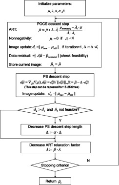
There are various ways of solving the intermediate constrained optimization problem in step 2. We use a gradient method that constantly alternates between projection-onto-convex-sets (POCS) and gradient descent of the objective function13, 28, 29 (see Appendix B). While with no theoretical guarantee to converge to the mathematically optimal solution, this method can efficiently reconstruct images with practically optimal qualities. The value of kmax is empirically determined by setting a threshold for the differences between two successive solutions. For example, the entire sequential process of the background image reconstruction in our simulation study is ended when k reaches kmax = 5, as the resulted image only differs slightly from when k = 4.
Two-stage image reconstruction
Binary image reconstruction
The idea of binary reconstruction30 is to obtain a binary image with the metal objects having high attenuation of 1 and the remaining background tissues having low attenuation of 0. Metal traces in the projection space are then determined by a forward projection of the binary metal image. The problem is to reconstruct an image from which the metal objects can be accurately extracted. In an image containing metal objects, the linear attenuation coefficients at the boundary of the metal change drastically. Ignoring the relatively much smaller gradient values, IG is approximately sparse only with substantial values on the boundary of the metal objects. The problem thus becomes reconstructing an image with extremely sparse gradient. The sequentially reweighted algorithm in Sec. 2A2 is applied here with representing the scanner-acquired projection data. By sequentially encouraging the image to have a highly sparse IG, we can recover the sharp edges of the metal boundary, leading to roughly two substantially different parts in the reconstructed image: the metal objects and the background, which can be binarized by simple thresholding.
ς is the essential parameter that regulates the sparsity of the IG. Following the argument in Sec. 2A2, ς should be set arbitrarily small to discourage the relatively low variations inside and outside the metal. However, when ς is close to zero, the reweighted algorithm becomes unstable and less capable of correcting inaccurate gradient estimates.19 This means that, if streak artifacts are generated somewhere in the sequential process, they are likely to persist in the image estimates and propagate along the subsequent optimizations. In our evaluations, ς is set empirically according to the variations of the attenuation coefficients to be reconstructed. For our digital QA example, the difference of attenuation coefficients between metal objects and tissues is around 0.5, while the variations within tissues or metals are [0.02, 0.16]. We chose ς = 0.01 because it eventually penalizes the smaller variations at least 1015 more and is sufficient to separate the image into two parts.
Background image reconstruction
To reconstruct the background image, i.e., the image excluding metal objects, the algorithm in 2A2 is applied with representing the projection measurements excluding the metal corrupted part identified in the previous stage. In this case, the sparse assumption is used to recover image from noisy, incomplete projection data. Unlike the binary reconstruction, we need to recover all the structures in the image without introducing oversmoothness, i.e., losing subtle variations within each specific structure. Enhanced IG sparsity is expected to lead to better preserved edges and improved image contrast. An appropriate ς enables SeqTV to steadily gain competitive edge over the unweighted counterpart in Eq. 1. In this work, the value of ς is manually chosen. A good value to start with would be the 90th percentile of the gradient magnitude of the FDK reconstructed image. We then move up and down to test out a few values and select the one that works best for the specific case. Once the background image is reconstructed, it is fused with the binary metal mask to form the complete image.
Data acquisition
Two simulation phantoms are used to evaluate the performance of the proposed algorithm. The first is a digital 2D QA phantom consisting of 350 × 350 pixels, 1 × 1 mm2 per pixel. The outer circle is composed of water, and the inner circular area is tissue equivalent material. The two circles have diameters of 210 and 90 mm, respectively. We have four objects lying within the inner circle, which are iron (left), brass (right), aluminum (upper), and bone (lower), each with a diameter of 12 mm. The iron object is designed to have a concave structure. The second is a 2D dental head phantom (350 × 350 pixels, 1 × 1 mm2 per pixel) designed similar to Ref. 6. Three disk-shaped dental fillings (silver, diameters 9, 8, and 7 mm) were inserted into the teeth. Four circular ROIs (diameter 18 mm) with a contrast of 150 HU respect to the soft tissue background were located between the teeth and dental fillings. Projection data are generated through a simulated projector for fan-beam CT geometry. The source-to-axis distance is 128.9 cm and the source-to-detector distance is 193.2 cm. The projection of each view consists of 500 × 1 pixels with detector bin size being 1 × 1 mm2. A total of 339 views are simulated over 360° rotation. A monochromatic spectrum is assumed and the photon energy is set to 80 KeV. Each projection value is computed from the known densities of the phantom along the ray and its intersection lengths with the corresponding pixels. The projection data generated from the simulator is noise-free. To simulate the noisy measurements, we use the following model:28, 31
| (7) |
where I0 is the incident x-ray intensity and is the background electronic noise variance. The noisy projection data are calculated as
| (8) |
where we set the threshold of Ii to 1 to enforce that the logarithm transform is applied on positive numbers.
A commercial calibration phantom CatPhan®600 (The Phantom Laboratory, Inc., Salem, NY) and an anthropomorphic head phantom are used in our experimental study. Cone-beam CT projection data are acquired by an Acuity simulator (Varian Medical Systems, Palo Alto, CA). The tube voltage was set to 125 kVp. The duration of x-ray pulse at each projection view was 10 ms during the acquisition of CBCT projection data. The x-ray tube current was set to 10 mA for CatPhan®600 and 80 mA for the head phantom. The projection data were acquired in full-fan mode with a full-fan bow-tie filter. The distance of source-to-axis is 100 cm and the source-to-detector distance is 150 cm. The number of projections for a full 360° rotation is 680. The dimension of each acquired projection image is 397 × 298 mm, containing 1024 × 76 8 pixels. The projection data at each projection view were down-sampled by a factor of 2 and only the average of the central two slices along axial direction was selected. The size of reconstructed image is two-dimensional with 350 × 350 pixels, 0.776 × 0.776 mm2 per pixel.
RESULTS
Digital QA phantom
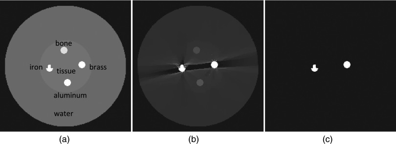
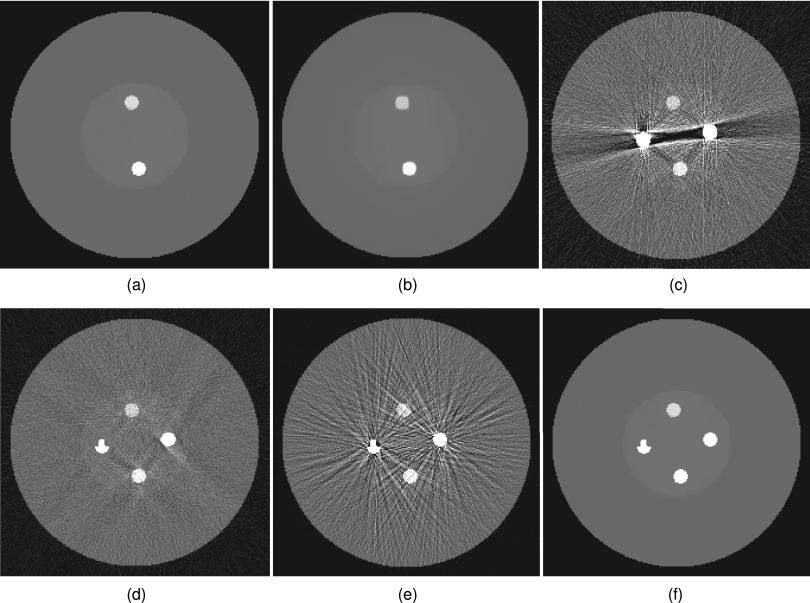
The projection data for the digital QA phantom are simulated by setting I0 = 2 × 10⁴, and = 10. Figure 1 shows the stage 1 reconstruction results with kmax = 10. The sequentially reweighted TV (SeqTV) optimization yields an image in which the two metal objects can be separated from the surrounding structures, as shown in Fig. 1b. Simple thresholding extracts all pixels associating with metal and gives the metal mask in Fig. 1c. To better show the comparison between SeqTV and unweighted TV, we designed two more challenging scenarios for stage 2 background image reconstruction: (1) An enhanced-noise scenario with I0 = 5 × 10³, and = 10; (2) A limited-view scenario by simulating only 29 views, equally spaced over 360° rotation. In Figs. 2a, 2b, we show the reconstructed background images from metal-trace-excluded projection data for the enhanced-noise scenario using SeqTV and unweighted TV methods. In Fig. 2f, we show the complete SeqTV reconstruction with the binary metal mask combined. SeqTV was compared with several analytical and iterative algorithms through Figs. 2c, 2d, 2e. Among them, FDK was applied to the original metal-corrupted projection data [Fig. 2c]. Severe streak artifacts can be observed in the FDK reconstruction and the image appears to be very noisy. Linear interpolation refers to that the projection is first linearly interpolated in the metal traces region based on the neighboring values and then back projected to the image domain. As shown in Fig. 2d, streak artifacts were reduced but noise was not effectively suppressed. In Fig. 2e, POCS was applied to the metal-trace-excluded projection by iteratively solving the data constraints 2, 3 alone. Apparently, POCS had very noisy reconstruction with extensive artifacts across the entire image domain. SeqTV not only removed the artifacts completely but also had the noise reduced significantly in the reconstructed image. Compared to TV, better preserved bone structure and soft tissue edges can also be observed in SeqTV reconstruction. Similar conclusions can be drawn from the observations through Figs. 3a, 3b, 3c, 3d, 3e, 3f, where SeqTV well reflected the ground truth even with significantly undersampled measurements. In comparison, FDK reconstructed an image completely dominated by artifacts. Linear interpolation and POCS had prominent artifacts residuals with severely blurred structures. In this case, SeqTV was superior to TV with vastly suppressed artifacts and better preserved image structures.
Figure 1.
Stage 1 SeqTV reconstructions for the digital QA phantom. (a) Ideal phantom; (b) SeqTV reconstruction (metal), sigma = 0.01, kmax = 10; (c) binary extraction from (b).
Figure 2.
Digital QA reconstructions for the enhanced-noise scenario. (a) SeqTV reconstruction (background), sigma = 0.1, kmax = 5; (b) TV reconstruction (background); (c) FDK reconstruction; (d) linear interpolation; (e) POCS reconstruction; (f) SeqTV, fused with metal mask.
Figure 3.
Digital QA reconstructions for the limited-view scenario. (a) SeqTV reconstruction (background), sigma = 0.1, kmax = 5; (b) TV reconstruction (background); (c) FDK reconstruction; (d) linear interpolation; (e) POCS reconstruction; (f) SeqTV, fused with metal mask.
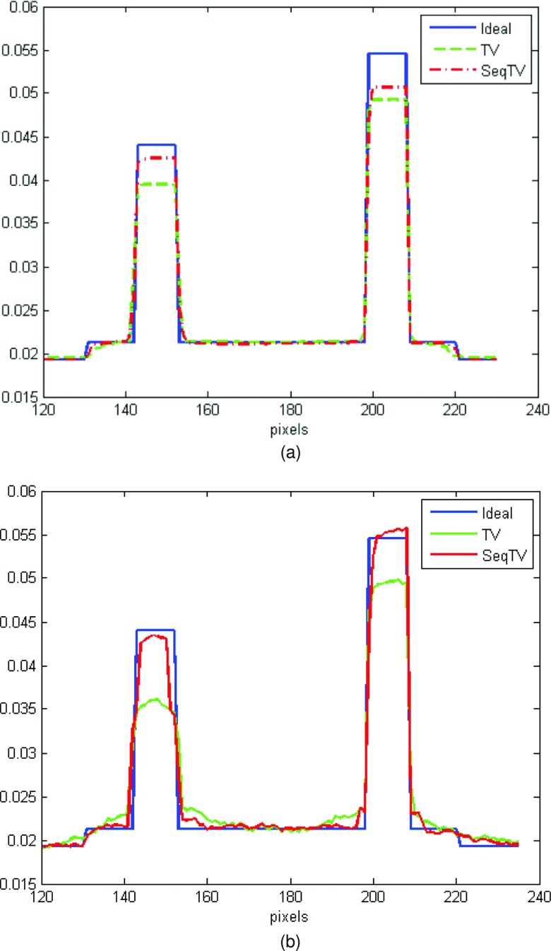
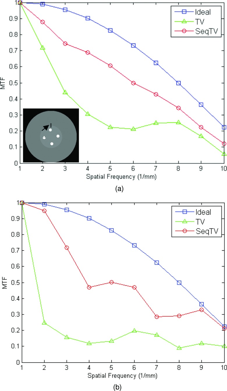
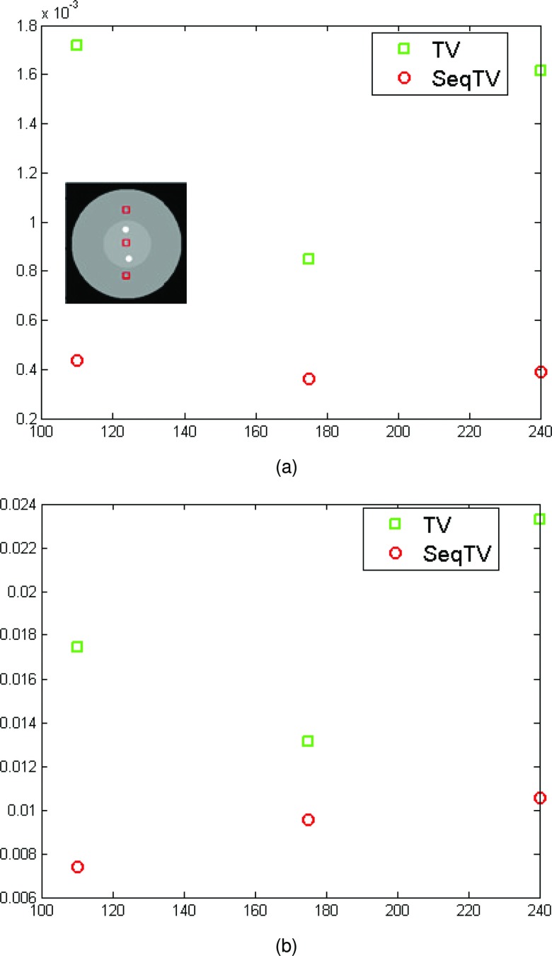
As can be seen, SeqTV and TV both perform well in suppressing streak metal artifacts with nearly invisible residuals. SeqTV, however, preserves the resolution better, especially along the edges of different structures. The complete SeqTV reconstruction, compared with the standard FDK, linear interpolation and POCS, is superior in terms of both artifacts reduction and noise suppression. Several criterions were used to quantify the performance and show further comparisons between SeqTV and TV. In Fig. 4, vertical profiles of the reconstructed linear attenuation coefficients through column 175 illustrate that, even for very noisy measurements [Fig. 4a] and limited number of views [Fig. 4b], SeqTV was able to recover the image that is fairly close to the ground truth and outperform TV especially on the edges. Furthermore, the modulation transfer function (MTF) that characterizes the spatial resolution of images was calculated for SeqTV, TV, and the ground truth. The line segment indicated by the black arrow in Fig. 5a provides a step function (edge spread function) from which the line spread function can be calculated by taking gradient and the MTF is obtained by one dimensional discrete Fourier transform. It can be observed from Fig. 5 that SeqTV produces better image resolution for both scenarios, which agrees with the observation in Figs. 23. Root-mean-square error (RMSE) is also computed to assess the image quality at three different regions shown in Fig. 6a. The ROI is defined as a 10 × 10 square and the RMSE is calculated by
| (9) |
where the summation is over the ROI. Lower RMSEs for SeqTV are consistent with the observations from previous figures.
Figure 4.
Vertical profiles of the reconstructed attenuation coefficients through the 175th column for TV and SeqTV in Figs. 23. (a) Enhanced-noise scenario; (b) limited-view scenario.
Figure 5.
MTF curves for TV and SeqTV reconstructions in Figs. 23, calculated from the indicated line segment. (a) Enhanced-noise scenario; (b) limited-view scenario.
Figure 6.
RMSEs for TV and SeqTV reconstructions in Figs. 23, calculated from the indicated squares. (a) Enhanced-noise scenario; (b) limited-view scenario.
Dental head phantom
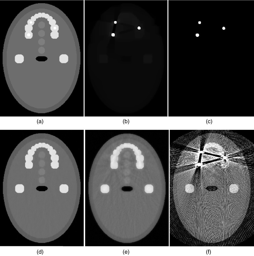
The 2D dental phantom [as shown in Fig. 7a] was constructed to represent one of the most challenging cases in CT metal artifact reduction. Four circular ROIs were designed to locate inbetween the metal fillings and teeth specifically to quantify the soft tissue contrast in regions most affected by the streak artifacts. The stage 1 SeqTV reconstruction, as shown in Fig. 7b, roughly separates the image into two parts: dental fillings and the background with blurred structures. The binary metal mask was extracted from Fig. 7b, as shown in Fig. 7c. Figures 7d, 7e show the stage 2 background reconstructions using SeqTV and TV, respectively. It can be seen that SeqTV reconstruction is fairly close to the ideal phantom image and no streak artifacts are visually observable. In comparison, TV has slight residuals in regions near the metals, where a slight oversmoothing effect can also be observed. However, both methods significantly outperformed the FDK method, as shown in Fig. 7f. In FDK reconstruction, the streak artifacts are so extensive that they almost obscured all the detailed structures in the image.
Figure 7.
Dental phantom reconstructions. (a) Ideal phantom, three circular fillings embedded with diameters 9, 8, and 7 mm; (b) SeqTV reconstruction (metal), sigma = 0.05, kmax = 5; (c) binary extraction from (b); (d) SeqTV reconstruction (background), sigma = 0.1, kmax = 5; (e) TV reconstruction (background); (f) FDK reconstruction.
The contrast values of the four circular ROIs respect to the surrounding tissue are calculated as the absolute difference between the mean value of the region inside the ROI and the mean value of the background soft tissue. For SeqTV, the contrast values are (from upper to lower) 142.0, 143.5, 147.7, and 153.5 HU, as opposed to the ground truth of 150 HU. For TV, the values are 131.3, 110.3, 144.7, and 136.6 HU. Obviously, SeqTV achieves overall better soft tissue contrast, especially in regions severely affected by artifact residuals (ROI2, which locates in the center of three disk fillings).
Experimental CatPhan®600
Initial experimental study was conducted using the CatPhan®600 with a regular hexagon-shaped metal screw embedded in the central region. The projection data were acquired using low-dose protocol. Extensive streak artifacts are present in the FDK result as shown in Fig. 8a. Figure 8b presents the FDK reconstruction without metal presence, which serves as a reference image for subsequent quantifications. The stage 1 SeqTV reconstruction and the extracted binary metal image are shown in Figs. 8c, 8d. Combined with the reconstructed background image, the complete reconstructions using TV and SeqTV are shown in Figs. 8e, 8f, in which the streak artifacts almost completely subsided.
Figure 8.
Reconstructions for CatPhan®600 using 339 views. (a) FDK reconstruction; (b) FDK reconstruction without metal (REF image); (c) SeqTV reconstruction (metal), kmax = 5, sigma = 0.001; (d) binary extraction from (c), all pixels within the extracted contour were considered metal pixels; (e) TV reconstruction; (f) SeqTV reconstruction, sigma = 0.001, kmax = 5. Both (e) and (f) are fused with metal mask.
Several circles of different intensities in the CatPhan®600 can be used to quantify the contrast-to-noise ratio (CNR) of the reconstructed images. Four circles indicted by black arrows in Fig. 8b are selected as the ROI for the calculation of CNRs for different algorithms. The contrast was calculated as the absolute difference between the mean value of the region inside the ROI and the mean value of the uniform background region, which is characterized by a uniform area of size 10 × 10 (in pixels) indicated by the black square. Standard deviation of the region inside the square was calculated to indicate the noise level. The CNR was defined as the contrast divided by the standard deviation. Table 1 lists the CNRs of FDK, the FDK reference image, unweighted TV, and SeqTV for the four indicated ROIs. Results indicate that, compared with the FDK algorithm, both unweighted TV and SeqTV are significantly better at suppressing noise without compromising much of the image contrast, while SeqTV in general outperforms the unweighted TV by producing better CNRs in all four ROIs.
Table 1.
CNR values of CatPhan®600 for the four ROIs indicated in Fig. 8.
| FDK | REF | TV | SeqTV | |
|---|---|---|---|---|
| ROI 1 | 2.93 | 3.29 | 35.7 | 43.3 |
| ROI 2 | 3.41 | 4.56 | 45.4 | 55.3 |
| ROI 3 | 1.09 | 1.33 | 12.1 | 14.9 |
| ROI 4 | 1.05 | 0.98 | 8.42 | 10.5 |
Anthropomorphic head phantom
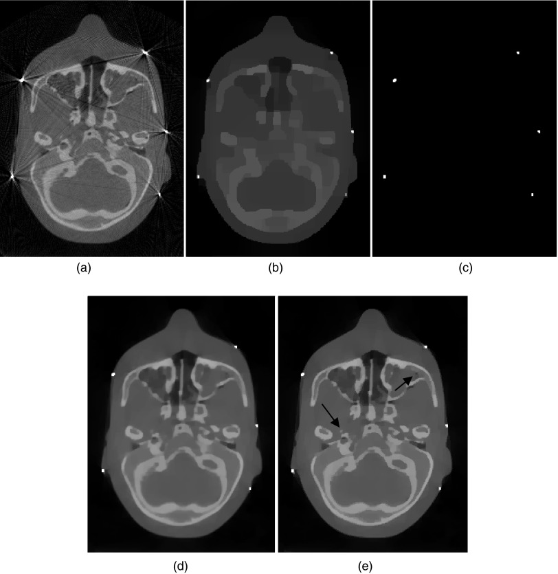
Figure 9 illustrates the results with five ball bearings inserted in an anthropomorphic head phantom. This is a case commonly seen in image-guided radiation therapy due to the existence of metallic fiducial markers. The FDK method [Fig. 9a] exhibits prominent artifacts caused by the BBs, which degrades the quality of the reconstructed image and makes accurate identification of the BBs difficult. Figure 9b shows the stage 1 SeqTV reconstruction from which the BBs are easily separable from the surrounding structures and the extracted binary metal image is shown in Fig. 9c. The reconstructed BBs appear in slightly different sizes because they are not placed exactly on the same plane when the CBCT data are acquired. Figures 9d, 9e are the metal-fused reconstructions using TV and SeqTV, respectively. Streak artifacts were effectively suppressed in both reconstructions. But for SeqTV, image was reconstructed with seemingly better contrast and preserved edges. In the regions indicated by arrows in Fig. 9e, it is seen that the structures were well preserved in the image reconstructed using SeqTV. The same structures were slightly blurred in TV reconstruction. This result is consistent with the observation and quantitative evaluation in the previous simulation and experimental studies.
Figure 9.
Reconstructions for the anthropomorphic head phantom using 678 views. (a) FDK reconstruction; (b) SeqTV reconstruction (metal), kmax = 10, sigma = 0.0001; (c) binary extraction from (b); (d) TV reconstruction; (e) SeqTV reconstruction, sigma = 0.001, kmax = 5. Both (d) and (e) are fused with metal mask.
Currently, the algorithm is not designed in favor of great computation efficiency, which depends highly on the optimization procedure in step 2. For the example in Fig. 1, SeqTV takes around 25 s to finish one loop on a 2.4 GHz, 2G RAM PC in step 2. Graphics processing unit (GPU) acceleration can be used in the future to save time on some segments of the algorithm.32
DISCUSSION AND CONCLUSION
In this paper, we proposed a sequentially reweighted optimization algorithm that exploits the gradient sparseness of general medical images for CT metal artifact correction. The results showed that the proposed method can effectively reduce streak artifacts and produce significantly improved CT images. Compared with the unweighted counterpart, it is advantageous in terms of improved image contrast and edge properties, as well as less visible artifacts and image noise. The reweighted scheme allows us to fully exploit the sparse assumption imposed on the IGs and establish a versatile method that reconstructs both the binary metal image and the background in a two-stage process.
The sequentially updated weights originate from the effort to find a measure that better approximates the l0-norm of the IG than the traditional l1-norm. By altering parameter ς, we gain better control of the IG sparsity, which gives the competitive edge over the unweighted TV minimization. It is, of course, not the only way of improving image quality by enhancing sparsity of the IG. In our previous work,28, 29, 30, 31, 33 we used a penalized smoothness (PS) function with an anisotropic prior and showed improved resolution and preserved edges in the reconstructed image. In the PS objective, the prior is adaptively changing with each update of the image during the optimization process. From the computing perspective, it is also a reweighting scheme in which weights are updated after each iteration. Mathematically, however, it makes more sense to fully evaluate a set of weights and update them based on the information gathered during the previous evaluation. Another merit of the proposed algorithm is that it provides a systematic way of updating weights based on a reweighting function. It is understandable that one can recover images with different levels of IG sparsity by choosing different weights in the weighted TV optimization, but these choices can be arbitrary and unguided. With the proposed reweighting function, the choice goes down to choosing parameter ς. The proposed algorithm is also systematic in terms the integrated two-stage image reconstruction. It not only reconstructs the background image, i.e., the image without the metal parts, but also provides a way of recovering the metal shapes and locations, which is by itself a valuable method in image-guided radiation therapy. The binary reconstruction is in fact crucial because the quality of background reconstruction highly relies on the accuracy of metal trace segmentations.
A possible limitation of the reweighted approach lies in the sparsity assumption on the IG, which is a common problem for all the sparsity-driven iterative approaches in medical image reconstruction. This affects SeqTV for background image reconstruction when images only have a mere level of sparseness on the IGs. Fortunately, the parameter ς allows us to readily control the aggressiveness in encouraging sparsity with TV being the limiting case as ς approaches infinity. By setting ς large the regularization of IG sparsity will be reduced. Even when the IG sparsity assumption does not hold, the algorithm should not yield worse images than applying EM-typed algorithms to comply with data constraints 2, 3 alone. Another potential problem is that, when applied to the metal-trace-removed incomplete projection data, iterative algorithms sometimes tend to be sensitive to the geometry mismatch between the simulated forward projector and the actual system configurations. This effect is eliminated in simulation study by using the same forward projector (represented by system matrix A) to generate projection data and do the reconstruction. In experimental and clinical studies, it requires us to cautiously model the forward projection and set high standard on experimental set-up and data acquisition.
In conclusion, we have developed a sequentially reweighed TV minimization method for CT image reconstruction in the presence of implanted metallic objects. The approach separates the reconstruction into two natural steps: (1) obtaining the shapes and locations of the metal objects; and (2) reconstruct the metal-excluded regions. With utilization of prior knowledge about the implanted metals as derived from the first step as well as the IGs of the reconstructed image through an effective reweighting of the total-variation, the proposed reweighted TV minimization provides a systematic approach for dealing with CT metal artifacts. With minor modification, the technique should be applicable to other “missing data” problems in image reconstruction or alike.34
ACKNOWLEDGMENT
This work was supported by grants from National Cancer Institute (1R01CA133474, 1R21CA15387-01) and National Science Foundation (NSF 0854492).
APPENDIX A: A DETAILED JUSTIFICATION OF THE WEIGHT CHOICES IN SEC. 2A2
To connect with the l0-norm, a logistic function is selected and a sequentially reweighted scheme is built on top of it. Consider the following function:
| (A1) |
Here we use the scalar case for simplicity. Consider the problem
| (A2) |
The change of variable is to overcome the fact that |x| is not differentiable at the origin. f(y) is concave and thus below its tangent.14 At a current solution yk, we can minimize a linearization of f(y) for a new update of yk + 1, that is,
| (A3) |
Thus the problem can be solved via the iteratively reweighted optimizations. This is a simple example of the Majorization Minimization algorithms and the linearization serves as a surrogate function majorizing the original objective function 1. By substituting |x| with the TV of the image, we have the weighting function in step 3 in Sec. 2A2.
The connection among the logistic function, the l1 and l0 norms gives analytical justification for why the reweighted scheme can improve the sparse signal recovery. When ς approaches zero, f(x) goes close to 1 which resembles the l0-norm for x ≠ 0. The value of ς actually determines the slope of f(x) at the origin. As ς → 0, f(x) is very steep near x = 0 and the slope is much greater than 1. Compare to the l1-norm it will give relatively large penalty to smaller x values and more strongly encourage them to be set to zero when we target on minimizing f(x). Therefore, the logistic function is likely to have more democratic penalization across different signal magnitudes than the l1-norm and thus better represents the l0-norm in this sense.
APPENDIX B: GRADIENT ALGORITHM FOR SOLVING THE WEIGHTED TV MINIMIZATION
In the sequentially reweighted TV algorithm, we need to solve the intermediate weighted TV minimization in step 2. In this study, it is performed using a gradient method that alternates between POCS and gradient descent, similar to that in Ref. 13.
The above gradient method does not guarantee the convergence to the mathematically optimal solution. However, it has been shown to be capable of finding a practically optimal solution in previous literature. The optimality criterion can be defined by setting a threshold on the number of iterations or some indicator function values derived from optimality conditions13, 28 (such as KKT conditions). In this work, we stopped the computations at a certain number of iterations at which a practically good-quality image was observed and good convergence was seen through the observation of consecutive reconstructions. In addition, the comparison between TV and SeqTV for background image reconstruction was made by setting the total number of iterations equal. For example, the TV reconstruction in Fig. 7b was obtained with 500 iterations, in comparison to the SeqTV reconstruction [Fig. 7a] with 200, 100, 100, 50, and 50 iterations (kmax = 5). Fewer iterations were required eventually because the end results from the current optimization were used to initialize the subsequent optimization in this study. By evaluating the performance under approximately the same computation time, we try to make the comparison between TV and SeqTV fair practically, as SeqTV is presumably more time consuming due to sequential optimizations with unweighted TV being the initial one.
References
- Mahnken A. H., Raupach R., Wildberger J. E., Jung B., Heussen N., Flohr T. G., Günther R. W., and Schaller S., “A new algorithm for metal artifact reduction in computed tomography,” Invest. Radiol. 38, 769–775 (2003). 10.1097/01.rli.0000086495.96457.54 [DOI] [PubMed] [Google Scholar]
- Srinivasa N., Ramakrishnan K. R., and Rajgopal K., “Image reconstruction from incomplete projection,” J. Med. Life Sci. Eng. 14, 1–19 (1997). [Google Scholar]
- Wang G. et al. , “Iterative deblurring for CT metal artifact reduction,” IEEE Trans. Med. Imaging 15, 657–664 (1996). 10.1109/42.538943 [DOI] [PubMed] [Google Scholar]
- Robertson D. D. et al. , “Total hip prosthesis metal-artifact suppression using iterative deblurring reconstruction,” J. Comput. Assist. Tomogr. 21, 293–298 (1997). 10.1097/00004728-199703000-00024 [DOI] [PubMed] [Google Scholar]
- Nuyts J., De Man B., and Dupont P., “Iterative reconstruction for helical CT: A simulation study,” Phys. Med. Biol. 43, 729–737 (1998). 10.1088/0031-9155/43/4/003 [DOI] [PubMed] [Google Scholar]
- Lemmens C., Faul D., and Nuyts J., “Suppression of metal artifacts in CT using a reconstruction procedure that combines MAP and projection completion,” IEEE Trans. Med. Imaging 28(2), 250–260 (2009). 10.1109/TMI.2008.929103 [DOI] [PubMed] [Google Scholar]
- Williamson J. F., Whiting B. R., Benac J., Murphy R. J., Blaine G. J., O’Sullivan J. A., Politte D. G., and Snyder D. L., “Prospects for quantitative computed tomography imaging in the presence of foreign metal bodies using statistical image reconstruction,” Med. Phys. 29, 2404–2418 (2002). 10.1118/1.1509443 [DOI] [PubMed] [Google Scholar]
- Montanari A., “Graphical models concepts in compressed sensing,” Compressed Sensing: Theory and Applications, Cambridge University Press, pp. 394–438 (2012).
- Candes E., Romberg J., and Tao T., “Robust uncertainty principles: Exact signal reconstruction from highly incomplete frequency information,” IEEE Trans. Inf. Theory 52, 489–509 (2006). 10.1109/TIT.2005.862083 [DOI] [Google Scholar]
- Candes E., Romberg J., and Tao T., “Stable signal recovery from incomplete and inaccurate measurements,” Commun. Pure Appl. Math. 59, 1207–1223 (2006). 10.1002/cpa.20124 [DOI] [Google Scholar]
- Chen G. H., Tang J., and Leng S., “Prior image constrained compressed sensing (PICCS): A method to accurately reconstruct dynamic CT images from highly undersampled projection data sets,” Med. Phys. 35(2), 660–663 (2008). 10.1118/1.2836423 [DOI] [PMC free article] [PubMed] [Google Scholar]
- Leng S., Tang J., Zambelli J., Nett B., Tolakanahalli R., and Chen G. H., “High temporal resolution and streak-free four-dimensional cone-beam computed tomography,” Phys. Med. Biol. 53(20), 5653–5673 (2008). 10.1088/0031-9155/53/20/006 [DOI] [PMC free article] [PubMed] [Google Scholar]
- Sidky E. Y. and Pan X., “Image reconstruction in circular cone-beam computed tomography by constrained, total-variation minimization,” Phys. Med. Biol. 53, 4777–4807 (2008). 10.1088/0031-9155/53/17/021 [DOI] [PMC free article] [PubMed] [Google Scholar]
- Choi K., Wang J., Zhu L., Suh T.-S., Boyd S., and Xing L., “Compressed sensing based cone-beam computed tomography reconstruction with a first-order method,” Med. Phys. 37(9), 5113–5125 (2010). 10.1118/1.3481510 [DOI] [PMC free article] [PubMed] [Google Scholar]
- Gao H., Li R., Lin Y., and Xing L., “4D cone beam CT via spatiotemporal tensor framelet,” Med. Phys. 39(11), 6943–69436 (2012). 10.1118/1.4762288 [DOI] [PMC free article] [PubMed] [Google Scholar]
- Liu B., Wang G., Ritman E. L., Cao G., Lu J., Zhou O., Zeng L., and Yu H., “Image reconstruction from limited angle projections collected by multisource interior x-ray imaging systems,” Phys. Med. Biol. 56(19), 6337–6357 (2011). 10.1088/0031-9155/56/19/012 [DOI] [PMC free article] [PubMed] [Google Scholar]
- Tibshirani R., “Regression shrinkage and selection via the Lasso,” Journal of the Royal Statistical Society, Series B (Methodological) 58, 267–288 (1996). [Google Scholar]
- Feigenberg S. J., Paskalev K., McNeeley S., Horwitz E. M., Konski A., Wang L., Ma C., and Pollack A., “Comparing computed tomography localization with daily ultrasound during image-guided radiation therapy for the treatment of prostate cancer: A prospective evaluation,” J. Appl. Clin. Med. Phys. 8(3), 2268–2279 (2007). 10.1120/jacmp.v8i3.2268 [DOI] [PMC free article] [PubMed] [Google Scholar]
- Candes E. J., Wakin M. B., and Boyd S. P., “Enhancing sparsity by reweighted l1 minimization,” J. Fourier Anal. Appl. 14, 877–905 (2008). 10.1007/s00041-008-9045-x [DOI] [Google Scholar]
- Figueiredo M. A. T. and Nowak R. D., “A bound optimization approach to wavelet-based image deconvolution,” Image Processing, 2005. ICIP 2005. IEEE International Conference on. Vol. 2. IEEE, 2005.
- Figueiredo M. A. T., Bioucas-Dias J. M., and Nowak R. D., “Majorization-minimization algorithms for wavelet-based image restoration,” IEEE Trans. Image Process. 16(12), 2980–2991 (2007). 10.1109/TIP.2007.909318 [DOI] [PubMed] [Google Scholar]
- Chartrand R. and Yin W., “Iteratively reweighted algorithms for compressive sensing,” Acoustics, Speech and Signal Processing, 2008. ICASSP 2008. IEEE International Conference on. IEEE, 2008.
- Wipf D. P. et al. , “A new view of automatic relevance determination,” Advances in Neural Information Processing Systems 20, 1625–1632 (2008). [Google Scholar]
- Zou H., “The adaptive Lasso and its oracle properties,” J. Am. Stat. Assoc. 101(476), 1418–1429 (2006). 10.1198/016214506000000735 [DOI] [Google Scholar]
- Sidky E. Y., Reiser I., Nishikawa R. M., Pan X., Chartrand R., Kopans D. B., and Moore R. H., “Practical iterative image reconstruction in digital breast tomosynthesis by non-convex TpV optimization,” Proc. SPIE 6913, 691328 (2008). 10.1117/12.772796 [DOI] [Google Scholar]
- Ramirez-Giraldo J. C., Trzasko J., Leng S., Yu L., Manduca A., and McCollough C. H., “Nonconvex prior image constrained compressed sensing (NCPICCS): Theory and simulation on perfusion CT,” Med. Phys. 38(4), 2157–2167 (2011). 10.1118/1.3560878 [DOI] [PMC free article] [PubMed] [Google Scholar]
- Zhang Y., Mou X., and Yan H., “Weighted total variation constrained reconstruction for reduction of metal artifact in CT,” Nuclear Science Symposium Conference Record (NSS/MIC), 2010 IEEE. IEEE, 2010.
- Zhang X., Wang J., and Xing L., “Metal artifact reduction in x-ray computed tomography (CT) by constrained optimization,” Med. Phys. 38, 701–711 (2011). 10.1118/1.3533711 [DOI] [PMC free article] [PubMed] [Google Scholar]
- Zhang X., Wang J., and Xing L., “Metal artifact reduction in computed tomography by constrained optimization,” Proc. SPIE 7622, 6221T-7–6221T-9 (2010). [Google Scholar]
- Wang J. and Xing L., “A binary image reconstruction technique for accurate determination of the shape and location of metal objects in x-ray computed tomography,” J. X-Ray Sci. Technol. 18, 403–414 (2010). [DOI] [PubMed] [Google Scholar]
- Wang J., Li T., and Xing L., “Iterative image reconstruction for CBCT using edge-preserving prior,” Med. Phys. 36, 252–260 (2009). 10.1118/1.3036112 [DOI] [PMC free article] [PubMed] [Google Scholar]
- Pratx G. and Xing L., “GPU computing in medical physics: A review,” Med. Phys. 38(5), 2685–2697 (2011). 10.1118/1.3578605 [DOI] [PubMed] [Google Scholar]
- Meng B., Wang J., Xing L., “Sinogram preprocessing and binary reconstruction for determination of the shape and location of metal objects in computed tomography (CT),” Med. Phys. 37(11), 5867–5875 (2010). 10.1118/1.3505294 [DOI] [PMC free article] [PubMed] [Google Scholar]
- Kim H., Becker S., Lee R., Lee S., Shin S., Candes E., Xing L., and Li R., “Improving IMRT delivery efficiency with reweighted L1-minimization for inverse planning,” Med. Phys. (in press). [DOI] [PMC free article] [PubMed]


