

Abstract
Advances in fiber optic technology and miniaturized optics and mechanics have propelled confocal endomicroscopy into the clinical realm. This high resolution, non-invasive imaging technology provides the ability to microscopically evaluate cellular and sub-cellular features in tissue in vivo by optical sectioning. Because many cancers originate in epithelial tissues accessible by endoscopes, confocal endomicroscopy has been explored to detect regions of possible neoplasia at an earlier stage by imaging morphological features in vivo that are significant in histopathologic evaluation. This technique allows real-time assessment of tissue which may improve diagnostic yield by guiding biopsy. Research and development continues to reduce the overall size of the imaging probe, increase the image acquisition speed, and improve resolution and field of view of confocal endomicroscopes. Technical advances will continue to enable application to less accessible organs and more complex systems in the body. Lateral and axial resolutions down to 0.5 μm and 3 μm, respectively, field of view as large as 800×450 μm, and objective lens and total probe outer diameters down to 350 μm and 1.25 mm, respectively, have been achieved. We provide a review of the historical developments of confocal imaging in vivo, the evolution of endomicroscope instrumentation, and the medical applications of confocal endomicroscopy.
Key Terms: microendoscope, endomicroscope, optical imaging, fiber optics, in vivo, fluorescence, reflectance
INTRODUCTION
Scanning confocal microscopy is a well-established optical imaging technique offering significant advantages over conventional wide-field microscopic imaging.131 In addition to enhanced lateral and axial resolution, the confocal microscope has the ability to image selectively in depth by substantially rejecting out of focus light through the use of a confocal pinhole. This optical sectioning capability enables high resolution imaging of thick biological samples, such as tissue in vivo, without the need for tissue excision, fixation, and sectioning as is required for conventional histological processing.
The confocal microscope was invented by Marvin Minsky in 1955. The Minsky microscope was termed “confocal” because the condenser and objective lens had the same focal point.82 A point illumination source is focused into the sample, illuminating a single point at a time. The detection pinhole aperture passes light from the focus, but significantly rejects light from depths in the sample above and below the focal plane (Figure 1). To create a two or three dimensional image, the sample or the focal spot needs to be scanned laterally and axially. Both fluorescence and reflectance microscopy techniques have been integrated into confocal imaging for a wide array of applications. In particular, confocal microscopy has become a popular tool for high resolution imaging of cells and tissue.
Figure 1.
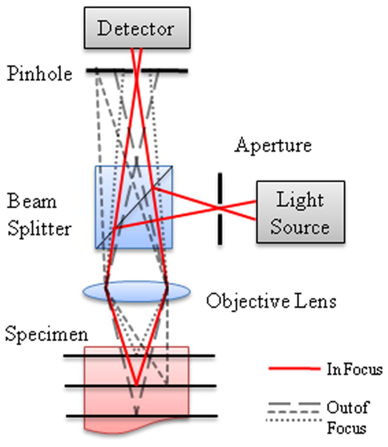
Schematic diagram for confocal microscopy showing rays coming from the focal spot (solid lines) and from out of focus regions above, below, and beside the focal spot (dashed lines). Out of focus rays are rejected by the confocal pinhole.
In the 1980’s and more extensively in the early 1990’s, confocal imaging was explored for in vivo imaging of animal and human tissue.44, 93 Early work was predominantly in accessible organs such as the eye,10, 63 skin,13, 89, 101 and oral cavity.89, 102 For in vivo imaging, the scanning and image acquisition rate must be sufficiently fast to avoid motion artifacts from a moving subject. In addition to increased imaging speed,92 microscope modifications were made to increase accessibility of the microscope to tissue. For example, in order to image tissue that could not be placed in a traditional confocal microscope, Rajadhyaksha et al. developed a confocal scanning laser microscope with a mechanical arm and rotatable head that allowed for imaging of skin, lip, and tongue in vivo.102, 103 A ring-and-template assembly was attached to the skin or oral tissue of the subject, which would then mount to the objective housing to minimize motion artifacts. However, the large microscope objective lens limits this method to in vivo imaging of externally accessible tissue.
A major advance for the translation of confocal microscopy to in vivo clinical imaging was the use of a single mode fiber in place of a traditional confocal pinhole, which has been shown to allow a microscope system to maintain the optical sectioning properties of a traditional confocal imaging system.30, 36, 60 The use of an optical fiber as the source and detector pinholes (Figure 2) allows separation of the imaging arm from the light source and detector, increasing versatility of the confocal microscope for in vivo imaging.17 This configuration reduces system complexity and enables automatic alignment of these two confocal apertures.14 With the implementation of optical fibers to deliver and collect light confocally from tissue, techniques for scanning in vivo and miniaturization of optics and mechanics at the distal end of the light guide encompass much of the technical innovation that has led to clinical endomicroscopy. In general, the scanning techniques can be divided into two modalities: scanning proximally or distally to the light guide. Various methods and technologies have been employed to miniaturize confocal systems so that they can be applied to endoscopic imaging. Although there are tradeoffs between resolution, field of view, and probe size, lateral and axial resolutions down to 0.5 μm64 and 3 μm,90 respectively, field of view as large as 800×450 μm,97 objective lens outer diameter down to 350 μm,95 and total probe outer diameter down to 1.25 mm have been achieved.
Figure 2.

Fiber confocal microendoscope configurations. (a) Proximally scanned microendoscope using a fiber bundle for illumination and detection. The beam is focused to a point and scanned in two dimensions or to a line and scanned in one dimension at the proximal face of the fiber bundle. (b) Distally scanned microendoscope using a single optical fiber for illumination and detection. Scanning can be accomplished by mechanically scanning the fiber, mechanically scanning the fiber and the miniature lens, scanning the beam with a MEMS mirror, or spectrally encoding one axis and mechanically scanning in the second axis. (c) Distally scanned microendoscope using two optical fibers, one for illumination and one for detection, in a dual-axes confocal configuration with a MEMS scanning mirror.
We take this opportunity in this review article on fiber-based confocal microscopy for in vivo imaging to define some terminology within this field. The terms “endomicroscope” and “microendoscope” are used interchangeably within the literature. Of the papers referenced in this review paper that use either of these two terms, 47% describe the technology as “endomicroscopy” and 63% use “microendoscopy”. Therefore, 10% overlap the two groups by using both terms within their text. There has not been a clear distinction between the terms. Here, to remove further ambiguity from the terminology, we define these terms in the context of endoscopy. First, a medical endoscope is a medical instrument that uses optical technology to visualize the inside of the body by passing through body orifices. Illumination and image transmission can be in the form of a long rigid or flexible tube that is able to reach the area of interest inside the body, or images can be wirelessly transmitted via radiofrequency waves to the external environment in capsule endoscopy. Confocal microscopy inside the body is accomplished using optical fiber technology for illumination and signal collection. Standard endoscopes can have a diameter up to a couple centimeters. An endomicroscope is a microscope that can be introduced inside an endoscope or directly in the body and provides microscopic images of the region of interest. A microendoscope is simply an endoscope that has a very small diameter, a few millimeters or less, that allows access to regions inaccessible to standard endoscopes. However, a microendoscope may not necessarily be a microscope. Several references use “confocal microendoscopy” to describe a miniature endoscope with confocal operation, therefore capable of acquiring microscopic images. We adopt the more precise term “confocal endomicroscopy” for a confocal microscope that can image inside the body.
The following paper reviews current technology, including commercially available systems, as well as the variety of clinical applications of confocal endomicroscopy. We specifically focus on single photon fluorescence and reflectance confocal imaging, because of the extent of clinical testing of these modalities, as opposed to multiphoton confocal endomicroscopy, for example. We refer the interested reader to other relevant review papers on various aspects of endomicroscopy. Additional information on fiber-based fluorescence imaging, including a discussion of two photon fluorescence imaging modalities, has previously been published by Flusberg et al (2005).26 While we present a variety of clinical applications, a review by Sokolov et al. (2002) provides a detailed discussion of endoscopic microscopy and its application to epithelial cancer detection.110 While we largely focus on technology and applications leading to clinical imaging, translation of this technology to clinical practice is a complex process with many challenges remaining to be addressed. A recent review by Liu et al. (2011) provides a detailed discussion of issues that need to be addressed for in vivo microscopy to become a standard clinical tool.77
INSTRUMENTATION
Confocal endomicroscopes generally fall within two main categories based on proximal or distal scanning and the type of light guide. Proximal scanning at the system side of the light guide is typically achieved through a coherent image guide that relays the scanned pattern to the tissue.32 The advantage of this technique is that the scanning system is not contained in the endoscopic probe and therefore the size of the scanning system is not limited. However, the resolution is limited by the spacing of the individual fibers within the fiber bundle and the total number of pixels is limited by the number of fibers in the bundle, ranging between 10,000 and 100,000 elements. To avoid this limitation, a single fiber can be used if the scanning technique can be moved to the distal or tissue end of the light guide. Using one or two single mode fibers, various techniques of distal scanning have been explored to reduce the endoscope size, increase image acquisition speed, and improve image quality. Table 1 summarizes the specifications for proximal and distal scanning confocal endomicroscopes in the research literature. In addition to describing the research behind confocal endomicroscope instrumentation, we present details on two commercially available confocal endomicroscopy systems, summarized in Table 2.
Table 1.
Specifications of confocal microendoscope probes
| Reference Number | Description | Tissue Space NA | Lateral Resolution (μm) | Axial Resolution (μm) | Field of View (μm×μm) |
|---|---|---|---|---|---|
| Proximal Scanning | |||||
| 62 | 30000 fiber bundle, 2 GRIN lenses, possible application through channel of endoscope, lens: 1 mm dia., 7.8 mm length | 0.5 | 3.1 | 16.6 | 280 dia. |
| 70 | 30000 fiber bundle, 2 GRIN lenses in 10 mm length of 18 gauge stainless steel tubing, probe inserted in 3.2 mm channel of bronchoscope | 0.5 | 1.4 | 16–26 | 230 |
| 59 | 30000 fiber bundle, custom objective with 7 lenses, rigid housing: 10 mm dia., 25 mm length | 0.45 | 3.3 | 50 | N/A |
| 117 | 30000 fiber bundle, custom objective in rigid micro- laparoscope, rigid housing: 5 mm dia., 350 mm length | 0.46 | 3 | 25 | 450 dia. |
| 67 | 30000 fiber bundle, custom objective with 3 lenses to be inserted in 18 gauge hypodermic needle | 0.4 | 0.9 | N/A | 250 dia. |
| 113 | 30000 fiber bundle, custom objective with 8 lenses, rigid housing: 7 mm dia., 22 mm length | 1 | 2 | 10 | 180×170 |
| 58 | No fiber, rigid probe, 3 GRIN lenses and side-viewing prism, rigid housing: 1.25 mm dia., 50 mm length | 0.45 | 1 | 10 | 250 dia. |
| 24 | No fiber, rigid probe, 10 rod relay lenses and a custom objective, rigid housing: 5 mm dia., 230 mm length | 0.9 | 1–2 | 5 | 400 dia. |
| Distal Scanning | |||||
| 31 | SF, 11 GRIN rod lenses and a hemisphere lens, lens: 1.5 mm dia., 89 mm length | N/A | 1.3 | 30 | 190 dia. |
| 95 | SF, 2 GRIN lenses housed in 22 gauge hypodermic needle, to be inserted through 18 gauge guiding needle, lens: 350 μm dia., 27 mm length | 0.29 | 0.87 | 11.5 | 70 dia. |
| 18 | SF, 2 MEMS scanners, off-axis phase grating lens, lens and scanner housing: 1.2×2.5 mm, 6.5 mm length | 0.24 | 1 | N/A | 100 dia. |
| 64 | SF, 2-axis MEMS scanner, objective of 2 doublets and a high NA lens, lens and scanner housing: 18 mm dia., 54 mm length | 0.48 | 0.5 | 4.2 | 200×125 |
| 109 | SF, 2-axis MEMS scanner, objective of 2 achromats and an aspheric lens, lens housing: 5 mm dia., 35 mm length | 0.33 | 0.83 | 9.55 | 140×70 |
| 91 | SF, unimorph fiber scanner, aspheric lens, lens and scanner housing: 3.5 mm dia., 30 mm length | 0.55 | 1 | 5.4 | 90×150 |
| 97 | Dual axis, 2-axis MEMS scanner, 2 parabolic mirrors and a hemisphere lens, lens and scanner housing: 10 mm dia. | 0.12 | 5 | 7 | 800×450 |
| 96 | SF, spectrally encoded with dual prism grating, high NA lens, rigid housing: 10 mm dia. | 0.9 | 1.1 | N/A | 658 dia. |
GRIN: gradient index lens; SF: single fiber; MEMS: microelectromechanical systems; dia.: diameter
Table 2.
Commercial confocal microendoscope probes
| Probes | Lateral Resolution (μm) | Axial Resolution (μm) | Field of View (μm×μm) | Working Distance (μm) | |
|---|---|---|---|---|---|
| Optiscan/Pentax ISC-1000 | 0.7 | 7 | 475×475 | 250 | |
| Mauna Kea Cellvizio | S | 5 | 20 | 600×500 | 0 |
| HD | 2–3 | 20 | 240×240 | 30–80 | |
| Z | 5 | 30 | 600×500 | 70 | |
| miniO | 1 | 3 | 240×240 | 30 | |
| AlveoFlex | 5 | 100 | 600×500 | 0 | |
Proximal Scanning
Miniaturization of the scanning optics required for a confocal microscope can be difficult and costly. To overcome this issue, the use of a fiber bundle in place of a single mode fiber has been demonstrated.32, 48 Optical fiber bundles are flexible light conduits made from tens of thousands of individual step-index fibers. Coherent image guides, in which the arrangement of the fibers is maintained along the length of the bundle, are extensively used in endoscopic imaging using white light illumination and wide-field detection. In addition, optical contrast techniques such as chromoendoscopy, fluorescence endoscopy, and narrow band imaging have been applied to wide-field endoscopy to improve diagnostic capability.130 In contrast to wide-field endoscopy, confocal endomicroscopy requires scanning of the beam across the face of the fiber bundle to exploit the confocal aperture of the individual optical fibers. Scanning can be accomplished using point scanning, slit scanning, or spatial light modulator techniques. A generalized configuration of proximally scanned confocal endomicroscopy is shown in Figure 2(a). Because the scanning occurs at the system side of the bundle, commercially available scanning optics can be employed. Illumination light is transmitted to the distal end of the bundle where miniaturized optics are needed to focus the light into the tissue, collect the reflected or fluorescent signal, and couple it back into the same fiber. The non-imaging space between fiber cores typically limits resolution and causes pixilation in the images; therefore, image processing is necessary to improve the image quality.66, 78
The first demonstration of the use of a fiber bundle for confocal imaging was presented by Gmitro and Aziz in 1993 using a standard Zeiss LSM10 confocal microscope in fluorescence mode to raster scan a 10,000 element coherent bundle.32 Although the optical sectioning capability of higher order modes is very similar to that of a single mode,132 Juškaitis et al. found speckle to be a problem in laser-based reflectance endomicroscopy through a fiber bundle in multimode operation.48 To address this, incoherent white-light illumination was scanned with a Nipkow disc tandem scanning microscope to produce the first real-time reflectance confocal endoscopic images using a 50,000 element bundle. Angle polishing of the fiber bundle and index matching were employed to reduce specular reflection from the proximal end of the fiber, a persistent challenge for reflectance confocal endomicroscopy through a fiber bundle. Collier et al. constructed an entire confocal microscope from commercial optics instead of using an existing confocal microscope.12 This system was later modified to include custom optics at the proximal and distal ends of the 30,000 element bundle to improve imaging performance and was used to image epithelial tissue.73, 112
Slit-scanning is an alternative fiber bundle scanning technique which uses a line illumination and slit aperture detector instead of a point source and pinhole detector to increase image acquisition speed with a slight sacrifice in axial resolution.107 Sabharwal et al. demonstrated an innovative slit-scanning fluorescence confocal endomicroscope with a single scanning mirror that scans the line illumination across the bundle, de-scans the fluorescent light for detection through the fixed slit aperture, then re-scans the spatially filtered signal onto a two-dimensional CCD camera to create real-time confocal images without the need for synchronization.107 Subsequently, Rouse and Gmitro modified the slit-scan system to demonstrate multispectral detection by incorporating a dispersing prism in the detection arm to collect both spatial and spectral information.104 Coherent image guides are the predominant type of bundle used for fiber bundle confocal endomicroscopy; however, Lin and Webb exploited the spatial scrambling of an incoherent fiber bundle to convert a slit-scan illumination to a parallel random point scan at the distal tip of the endoscope.75 The system has the simplicity of the slit-scan confocal endomicroscope and the optical sectioning capability of the point-scan technique. The image of the sample has to be reconstructed based on the random fiber mapping of the bundle.
Other scanning techniques include the use of spatial modulators. Lane et al. used a digital micromirror device with a high pixel count and fast response to sequentially illuminate individual or multiple fibers within a fiber bundle.68 Optical sectioning and contrast are improved by only illuminating fiber cores and not the non-imaging space between fibers. Recently, Thompson et al. presented a novel method analogous to adaptive optics to use a spatial light modulator to correct for phase aberrations in the fiber bundle and to additionally add curvature and tip-tilt to the wavefronts to focus and scan the beam at the distal tip of the fiber bundle without optical or mechanical components.123 While the use of a spatial light modulator was shown to allow three dimensional imaging, the reported system suffers from a very low frame rate. Acquisition for a single 50×50 pixel image was reported to take 15–20 minutes, with an axial resolution of approximately 100 μm and a field of view limited to 80 μm diameter.
Although the scanning mechanism does not need to be miniaturized for fiber bundle confocal endomicroscopy, a miniaturized high numerical aperture (NA) objective lens is still required to focus light into tissue and collect reflected or fluorescent signal. The main optical design challenge lies in achieving a doubly telecentric, high NA objective lens with minimized aberrations and a small outer diameter. Gradient index (GRIN) lenses are ideal for their small outer diameter; however, high NA GRIN lenses suffer from optical aberrations.62, 70 Consequently, GRIN lenses are usually assembled back to back or assembled with other high NA lenses. Custom complex glass lenses have been designed and fabricated for both fluorescence and reflectance confocal endomicroscopes.59, 74, 106, 107, 117 Plastic and combined glass and plastic miniature objectives have demonstrated the potential for inexpensive disposable endomicroscope probes.9, 11, 51, 52, 67 Custom designed lenses have been based on Amici, Petzval, and design by halves design methods.59, 74, 106 A more cost-effective approach is to start the design with commercial optics and add custom elements to correct aberrations.51, 52 In order to minimize back reflections, shorten the overall lens length, and reduce the complexity of assembly, a major design goal has been to reduce the number of optical elements in the miniature objective lenses.
A few endomicroscope specifications dictate the ease of use within the instrument channel of a flexible endoscope. In addition to a small outer diameter, the length of the endomicroscope must be sufficiently flexible and the rigid tip or imaging head of the endomicroscope must be short. While the minimum bending radius for a single optical fiber may be as low as 5 mm, the minimum bending radius for fiber bundles ranges from 10 mm for a 0.25 mm diameter bundle to 200 mm for a 3 mm diameter bundle. The drawback of reducing the bundle outer diameter is the concomitant reduction of the number of fibers in the bundle which corresponds to the number of pixels in the image. Even if the image guide is sufficiently flexible, the endomicroscope may not be able to be inserted into the instrument channel of a flexible endoscope or navigated through tortuous paths within the body if the rigid imaging head at the distal end of the probe is too long. Table 1 includes dimensions of the rigid sections of various endomicroscopes.
In benchtop confocal microscopic imaging of cellular or tissue samples, it is relatively easy to translate the sample using a translation stage to scan the specimen in the axial direction. Axial scanning is critical for many of the clinical endomicroscopy applications, but is much more challenging at the distal end of a fiber-based probe inside of a living body. Hydraulic, pneumatic, and mechanical scanners have been employed to scan the lens or the tissue. Additionally, optical axial scanning techniques have also been explored, such as the adaptive phase compensation approach previously mentioned.123 Gmitro and Rouse have optimized a depth scanning technique starting with their original design of a hydraulic focus mechanism in 2001.33 While the miniature objective lens was fixed relative to the position of the tissue, the fiber bundle was scanned by a piston controlled hydraulically. However, this system was not sufficiently compact and was susceptible to fluid leaks and air bubbles. Subsequently, a pneumatic design to control the fiber position relative to the lens was used as a focusing mechanism.105, 106 In this design, a manual micrometer was used to achieve depth scanning and focus which resulted in slow movement and inherent hysteresis. Therefore, a computer-controlled high speed positioning system that automatically corrected for hysteresis was developed with a positioning accuracy less than the axial resolution.116 Sung et al. employed hydraulic suction directly on the tissue to scan the tissue relative to the lens.113 Due to differences in tissue mechanical properties, hydraulic suction suffers from inaccuracies in positioning and the inability to know exact imaging depth. The possible introduction of air bubbles in the immersion medium is an additional challenge. Lane et al. demonstrated a promising technique to exploit the chromatic aberration of a GRIN lens to spectrally scan the working distance.69
Confocal endomicroscopes designed for clinical imaging are commonly flexible endoscopes with a short rigid section at the tip that houses the miniature objective lens and, in the case of distal scanning endoscopes, the miniature scanning mechanism. Laparascopes or rigid endoscopes have a longer rigid section in the form of a handheld device. A few rigid confocal endomicroscopes have been developed, primarily for preclinical applications, without the use of optical fibers. This is particularly useful for nonlinear optical microscopy where the dispersion in the long length of glass in an optical fiber may influence the laser pulse width. These rigid microendoscope designs typically have a small diameter lens system that can be inserted into an animal for intravital imaging. Depending on the imaging depth required, an image relay is commonly used to extend the length of the probe tip. Scanning is performed proximal to the miniature lens system and does not need to be miniaturized due to the location outside of the body. Without any flexibility in the optical system, this configuration is impractical for clinical use. However, a single fiber may be used to deliver the beam to the scanning system and lens and serve as the confocal pinhole.31, 95 Therefore, these rigid endoscopes potentially span distal scanning and proximal scanning depending on the scanning and fiber system arrangement. Multiphoton and confocal endomicroscopes have been implemented using GRIN doublets and triplets in a direct view 3, 23, 45, 57 or side viewing probe by adding a prism at the distal tip.27, 58 In 2010, Farahati et al. developed a rigid confocal endomicroscope using a series of rod lenses with a 0.9 NA miniature objective lens.24 In the same year, Feng et al. showed the design of the scan lens and the objective lens arranged into one long tube for a confocal endomicroscope.25
Distal Scanning
Confocal endomicroscopes employing various distal scanning mechanisms typically use one or two optical fibers for illumination and collection of light, illustrated in Figure 2(b) and 2(c) respectively. Kimura and Wilson first proved the use of a single mode fiber for confocal detection in 1991 by replacing the pinhole in a confocal microscope with an optical fiber.60 Miniaturization of objective lenses and scanning optics quickly followed in an effort to image inside the body.
In 1991, Giniūnas et al. built and tested a scanning confocal microscope using a single optical fiber for illumination and collection and as the confocal pinhole.30 Reflected light was coupled back into the laser for sensitive intracavity detection. The optical fiber and single hemisphere lens were fixed together in a scanning probe that was scanned using piezoelectric transducers in a Lissajous scan pattern. Benschop and Vanrosmalen exploited the two dimensional scanning of a compact disc player reading head by replacing the laser in the device with a fiber for remote delivery and confocal collection.5 In 1992, Juškaitis et al. scanned the object in a fiber-based system with intracavity detection.46 In later work, Juškaitis and Wilson demonstrated the use of a fiber coupler to separate illumination and detection paths, which were scanned synchronously to generate an image.47
As mentioned in the previous section, some rigid endoscopes that utilize single fibers for their confocal aperture and flexibility employ relatively large scanning systems at the distal end of the optical fiber. A long relay lens, frequently a GRIN lens, is used to offset the imaging field from the bulky scanning.31 Two dimensional mechanical scanning of a lensed fiber as an input into a long GRIN relay lens has also been shown to reduce off-axis aberrations that may be imposed by more traditional mirror scanning.95 Although the scanning mechanism is large, the 350-μm diameter GRIN rigid endomicroscope is mounted in a 22-gauge hypodermic needle to penetrate up to 15 mm into tissue. Other endomicroscopes employ electromagnetic or piezoelectric actuators to distally scan the fiber and objective lens, which are mounted together.23, 27, 38, 39, 86 This configuration also reduces off-axis aberrations through the single high-NA plano-aspherical lens.
Dickensheets and Kino pioneered the field of microelectromechanical systems (MEMS) based scanners for confocal endomicroscopes. In 1994, they presented the use of a resonant cantilever to scan a single fiber with a Fresnel zone-plate miniature objective lens.17 Later, the first use of micro-machined silicon scanning mirrors in single fiber endomicroscopy was demonstrated.18, 19 Two separate micro-mirrors placed at the distal end of the fiber scan the beam in two dimensions, and a miniature off-axis phase zone plate fabricated by etching fused silica serves as an objective lens. More recently, Dickensheets has developed a MEMS deformable mirror for focus control and aberration correction, to be integrated into a biomedical endoscope.20, 83 The main challenges in developing miniaturized scanning mirrors are to achieve a robust device with large scan angles, large mirror dimensions, and sufficiently fast scanning within a small package. Murakami at Olympus Optical Co. developed a prototype 3.3-mm diameter confocal endomicroscope to pass through a working channel of an endoscope using a single MEMS electrostatic gimbal scanning mirror and an aspherical objective lens.84, 85 Other two-axis scanning mirror designs used in confocal endomicroscopy include an electrostatically driven torsional silicon micro-mirror with electroplated nickel hinges and frame,40 a gimbaled scanner using electrostatic combdrive actuators,64, 79, 109 and a thermally actuated non-resonant scanner fabricated using silicon-on-insulator multi-user MEMS processes (SOIMUMPS).98 In addition to micromirrors, other microdevices to mechanically scan the fiber, such as unimorph cantilevers, have also been used for scanning.91 Integrated optical focusing and mechanical scanning devices have also been fabricated.2, 65
High resolution confocal endomicroscopes typically require high NA miniature objective lenses which inherently have a short working distance. Consequently, post-objective beam scanning is impractical within this short working space. To overcome this limitation, Wang et al. introduced a novel optical sectioning technique using a dual-axes geometry.127 The depth of focus of a low NA lens is too large for adequate optical sectioning in tissue; however, by crossing the axes of two separate illumination and collection beam paths, improved resolution and a long working distance can be achieved with low NA lenses. This enables post-objective scanning,126 which has been accomplished with a biaxial barbell-shaped MEMS scanning mirror.76, 97 Dual-axes reflectance and fluorescence confocal endomicroscopy have been implemented using various excitation wavelengths, and engineering improvements continue to reduce the size of the probe head.97, 100
In vivo endomicroscopic imaging requires fast image acquisition rates, on the order of 10 frames per second or faster, to avoid motion artifacts. High fidelity distal scanning in two dimensions is challenging at these speeds in a compact package. To eliminate one axis of mechanical scanning, Tearney et al. introduced the concept of spectrally encoded confocal microscopy.119 A broadband source is dispersed laterally by a diffraction grating so that the spatial position is encoded in the wavelength. All wavelengths can be transmitted through a single fiber and the spatial position of the reflected light can be decoded by spectral detection.120 The second axis of scanning can be performed with a piezo-electric transducer. Image acquisition rates up at 30 frames per second were achieved by using a rapid wavelength swept source.6 A dual prism grating element was used to miniaturize the probe head.96 The addition of a motor shaft and linear stage for helical scanning was used to demonstrate large area spectrally encoded confocal imaging of luminal surfaces.135
Commercial Confocal Endomicroscopy Systems
Two commercial confocal endomicroscopy systems are currently in use in clinical applications. The Pentax ISC-1000 confocal endomicroscopy system with the EC3870CIK scope (Pentax/Hoya, Tokyo, Japan and Optiscan Pty Ltd, Notting Hill, Victoria, Australia) is a miniaturized Optiscan confocal endomicroscope incorporated into a conventional video-endoscope. The second system approved for clinical use is the Cellvizio (Mauna Kea Technology, Paris, France). The Cellvizio is a standalone imaging system based on a fibered technology capable of being incorporated into a conventional endoscope.90 Cellvizio confocal miniprobes can be passed down the accessory channel of any standard endoscope, allowing for rapid image capture in vivo in real time.
The Optiscan confocal endomicroscope was developed out of the work of Delaney and Harris.15, 16 The technical specifications of the Optiscan/Pentax ISC-1000 system presented here are summarized from Polglase et al.99 A distally-scanned single optical fiber serves as both the illumination and detection confocal pinholes. The beam is raster-scanned by scanning the fiber with an electromagnetically driven scanning mechanism. The fiber and lens are contained within the probe and coupled to the sample via an optical window. The window is placed in contact with the tissue to stabilize the probe and to create a reference point for axial scanning. A z-actuator, with button controls on the endoscope handpiece, provides depth scanning from 0 to 250 μm beyond the window surface. Images can be acquired at 0.7 seconds per frame at 1024×512 pixels or 1.2 seconds per frame at 1024×1024 pixels. The maximum output of the endomicroscope is 1 mW at 488 nm wavelength. The confocal microscopy component of the integrated endoscope system is 5 mm of the total 12.8 mm diameter. In addition to the confocal component, the integrated video-endoscope includes two light guides, an imaging CCD, a biopsy channel, air and water jet channels, and an additional water jet channel that is used for topical application of contrast agents, such as acriflavine. Table 2 summarizes the technical specifications of the Optiscan/Pentax ISC-1000 confocal endomicroscope. The Pentax ISC-1000 system is designed for imaging the lower gastrointestinal (GI) tract, but has also been used for imaging the stomach, duodenum, distal esophagus, and even the cervix.50, 53, 61, 115
The second clinically available endomicroscopy system is the Cellvizio (Mauna Kea Technologies, Paris, France), a probe-based endomicroscopy system. Confocal imaging is achieved through the use of miniprobes, that can be inserted in the accessory of any standard endoscope.22 Unlike the distal scanning of the Pentax system, the Cellvizio incorporates a proximally-scanned fiber bundle to deliver 488 nm wavelength laser light to the sample. An example fiber bundle employed by Mauna Kea Technologies is composed of 30,000 optical fibers, with a fiber inter-core distance of 3.3 μm and fibre core diameter of 1.9 μm.71
The Cellvizio system is composed of a Laser Scanning Unit, a range of fibered objectives, and dedicated software which allows for obtaining images at a rate of 12 frames per second. The Cellvizio was developed using a 488 nm Sapphire laser, followed by another model which featured a 660 nm source for reflectance imaging.125 Real time imaging is achieved using a 4 kHz oscillating mirror for horizontal line scanning and a galvanometric mirror for frame scanning, resulting in a raster pattern that is scanned across the surface of the fiber bundle.66 A custom image processing algorithm is then used to correct for any artifacts that have occurred while imaging through a fiber bundle.66
Imaging parameters of the Cellvizio system range with the variety of Confocal Miniprobes that have been developed for use with the base unit. These probes differ by their distal optics and their bundle characteristics and vary in flexibility, size, sensitivity, and resolution in order to meet the different clinical or research needs. Table 2 outlines the main characteristics of the different probes developed for clinical research.90 Each probe also houses a small electronic chip which is used by the base unit for probe identification. The Cellvizio system does not allow for modification of the depth of the focal plane; the focal plane of each Confocal Miniprobe is fixed. However, the appropriate Confocal Miniprobe with a specific working distance can be selected for the application.
To make a general comparison between the two commercial systems, the Pentax ISC-1000 is a distally scanned confocal endomicroscope that is incorporated in a conventional video-endoscope, while the Cellvizio Confocal Miniprobes are proximally scanned probes that may be used independently or incorporated into any standard endoscope. The Pentax reports excellent lateral and axial resolution for a fixed field of view. The miniO Cellvizio Miniprobe also has excellent lateral and axial resolution with a smaller field of view. If a greater field of view is necessary, resolution can be sacrificed by switching to a different Miniprobe. The Pentax has an axial scanning mechanism allowing the user to adjust the depth of the image plane in the sample; whereas, the Miniprobes have fixed working distances. The Cellvizio has a significantly faster acquisition rate than the Pentax, which can be critical for imaging in vivo. Additionally, Cellvizio has an outstanding software and image processing package, including video mosaicing to extend the image field of view.
MEDICAL APPLICATIONS OF CONFOCAL ENDOMICROSCOPY
Early in vivo confocal imaging was first performed on the eye, mouth, and skin.10, 13, 102, 129 These accessible organs were used to demonstrate the in vivo cellular imaging capability of confocal imaging. However, standard microscope objective lenses, even on fiber coupled handheld probes, are incapable of imaging cavities within the body. With advancing technology, as presented in this review, endomicroscopic probes are sufficiently small in size to more readily access areas within the body such as the GI tract, bladder, cervix, ovary, oral cavity, and lung. Here, we present a selection of results from clinical studies of confocal endomicroscopy.
Gastrointestinal Tract
Confocal endomicroscopy has been most extensively applied to detection of diseases in the GI tract. The Optiscan/Pentax ISC-1000 has been used in numerous studies for in vivo imaging of cellular morphology of the mucosa in the upper and lower GI tract.99 Cellular and subcellular structures, such as nuclei within the mucosa, colon crypts, stomach villi, and gastric pits are visible in the images. Squamous epithelium from the distal esophagus was also imaged. Fluorescent dyes are commonly used to provide contrast in fluorescence imaging of tissue. Acriflavine is administered topically to visualize nuclei, and fluorescein is administered intravenously to see the extracellular matrix and lamina propria. Figure 3 demonstrates the features visualized in the normal colon using these exogenous contrast agents. The Mauna Kea Cellvizio probe-based endomicroscopes have also been used in the upper and lower GI tract.81
Figure 3.

In vivo endomicroscopic imaging of the normal colon using Optiscan/Pentax (A) first prototype with 6 mm outer diameter and (B–D, F) second prototype with 5 mm outer diameter and integrated into the Pentax EC3870K video-endoscope. Tissue stained with topical application of acriflavin (A–B) and intravenous fluorescein (C–D). (A) Rectal mucosa; (B) descending colon mucosa; (C) cecum; (D) deeper layers of the lamina propria showing microvasculature in the descending colon; (F) terminal ileum. (E) Hematoxylin and eosin stained tissue section cut parallel to the tissue surface for comparison to en face confocal images. 500×500 μm field of view for all images. Reprinted from Gastrointestinal Endoscopy, 62(5), Polglase et al., p. 686–695, Copyright 2005, with permission from Elsevier.99
Olympus (Olympus Optical Co. Ltd., Tokyo, Japan) explored the development of a endomicroscope for use in the working channel of an endoscope to image mucosa in the GI tract.108 Although exogenous contrast agents were not necessary to detect signal in reflectance confocal mode, the images had poor contrast and resolution, limiting resolution of nuclei within the tissue. Another confocal reflectance endomicroscopy study was performed on esophageal and stomach tissue using a prototype Mauna Kea reflectance confocal probe with improved contrast and resolution.87
Barrett’s Esophagus
Patients with acid reflux may develop Barrett’s esophagus as a result of irritation of the epithelial lining of the esophagus from stomach acid. These patients are at a higher risk of incidence of adenocarcinoma in the esophagus. The first endomicroscopy study of Barrett’s esophagus was conducted with promising results.56 A method for classification of confocal images based on vasculature and cellular architecture was developed and presented with example images for prediction of histopathology of normal gastric epithelium, Barrett’s epithelium, and neoplasia. Based on this classification system, Barrett’s esophagus was predicted with 98.1% sensitivity and 94.1% specificity. Furthermore, Barrett’s-associated neoplasia was predicted with 92.9% sensitivity and 98.4% specificity.
The current technique for monitoring neoplastic development in Barrett’s esophagus is four-quadrant biopsy, which is susceptible to sampling error. Using the Mauna Kea probe-based endomicroscope, a prospective study has shown that in vivo confocal imaging is “non-inferior” to the standard quadrant biopsy.1 Although, the technique has potential to exclude neoplasia, it may not replace histology for surveillance of Barrett’s esophagus. However, endomicroscopy may improve diagnostic yield by guiding biopsy to the area with the highest risk of neoplasia.
Celiac Disease
Celiac disease causes damage to the villi of the small intestine prohibiting vital nutrients from being absorbed into the bloodstream. This disease causes the stomach to be intolerable to gluten, which is common in many foods. Confocal laser endomicroscopy has shown potential to diagnose celiac disease.72, 136 After imaging the duodenum in 6 patients followed with biopsies of the interrogated tissue, confocal laser endomicroscopy successfully aided a pathological diagnosis of 4 normal and 2 positive for celiac disease.136 Another study supports diagnosis of celiac disease with sensitivity of 94% and specificity of 92% using confocal endomicroscopy and suggests that abnormalities not seen in histology could possibly be detected.72
Inflammatory Bowel Disease
Patients with inflammatory bowel disease, including ulcerative colitis and Crohn’s disease, have an increased risk of developing colorectal cancer and are recommended to begin colonoscopy screening at an earlier age. Random or step biopsy may be recommended for surveillance in ulcerative colitis, which is prone to sampling error. Confocal endomicroscopy is being evaluated as a tool to target regions suspicious for neoplasia to guide biopsy in patients with ulcerative colitis. Differences can be seen between endomicroscopic images of normal tissue and non-active or active ulcerative colitis.128 Normal colon mucosa has crypts that are small and regularly arranged within the tissue. Non-active ulcerative colitis also displays small crypts, but in an irregular arrangement, while active ulcerative colitis has an unidentifiable structure with large crypt lumens. In future research, it will be important to determine whether low-grade dysplasia can be differentiated from benign lesions with inflammation.
Colorectal Cancer
The colon and rectum are in the top five sites for cancer incidence in the United States, with an age-adjusted incidence approaching 50 per 100,000 people.41 Additionally, colorectal cancer has a low 5-year relative survival rate of 64%. Patients with high risk for colorectal cancer based on personal or family history are recommended to have periodic colonoscopy screening. Colorectal cancers primarily originate in adenomatous polyps, which are typically removed during endoscopic evaluation, whether they are neoplastic or not. Some lesions develop from flat or depressed lesions that are difficult to detect by traditional white light endoscopy, and would also be difficult to detect with confocal endomicroscopy based on the small field of view. Kiesslich et al. published the first results on the diagnostic capability of confocal endomicroscopy in colorectal intraepithelial neoplasia and cancer in 2004.53 The goal was to predict histology while patients were undergoing a colonoscopy screening for colorectal cancer. Neoplastic changes within the tissue were predicted with high accuracy, including a sensitivity of 97.4% and specificity of 99.4%. The classification of confocal images was based on patterns in the vessel and crypt architecture. As mentioned previously, normal crypts are regularly arranged in a hexagonal pattern, while neoplastic tissue is distorted and irregular. This method would allow for faster diagnosis of endoscopically observable neoplasia and would potentially limit the number of unnecessary biopsies. In contrast to intraepithelial neoplasia and cancer, hyperplastic polyps are considered to be non-neoplastic tissue and are not required to be removed. A recent prospective study from another group to differentiate adenomas from non-neoplastic polyps using a basic classification system reported a sensitivity of 93.9% and a specificity of 95.9% compared with histology.134 Meining et al. reported similar results using the probe-based endomicroscopy with a sensitivity of 92.3% and specificity of 91.3%.81
Gastric Cancer
Gastric cancer is speculated to be a multistep progression that is initially triggered by an infection of helicobacter pylori (H pylori), which progresses to intestinal metaplasia, chronic gastritis, intraepithelial neoplasia, and then cancer. With the aid of confocal endomicroscopy, H pylori may be diagnosed in the gastric epithelium in vivo.54 Confocal images of gastric mucosa demonstrate similarities with histology images for fundic gland mucosa, pyloric gland mucosa, and adenocarcinoma of the stomach.61
While confocal imaging in the GI tract has predominantly been performed in fluorescence mode using exogenous contrast agents, reflectance confocal endomicroscopy was also evaluated for the diagnosis of gastroesophageal cancer in its early stages.87 Features of the normal esophagus show high reflectivity from nuclei and cellular honeycomb-like structure. Cancer in the esophagus appeared to have an increase in nuclear to cytoplasmic ratio, and the reflectivity from cell membranes was not seen. Normal gastric mucosa exhibits crypt cells arranged in a flower pattern around the gastric pit. Within differentiated adenocarcinoma, cell membranes were not apparent and glandular structures were disorganized.
Urinary Tract
Confocal laser endomicroscopy was performed using the Cellvizio instrument by Mauna Kea Technologies to image the human bladder in vivo.111 Fluorescein was administered intravesically and/or intravenously following the standard white light cystoscopy procedure. Fluorescein provided contrast allowing for differentiation between normal bladder mucosa and low and high grade bladder tumors. Large umbrella cells near the surface with smaller cells nearing the lamina propria were visible in the bladder mucosa. Tumors classified as low grade had normal appearing small cells that were densely packed. In contrast, high grade bladder tumors had an irregular architecture.
A paper published from the same group sought to develop criteria for diagnosing benign and neoplastic mucosa along the urinary tract using confocal endomicroscopy.133 Here, the Cellvizio system was used in conjunction with white light cytoscopy for faster diagnosis of urinary tract conditions such as bladder cancer. Confocal images taken along the urinary tract are seen in Figure 4 with fluorescein as a contrast agent.133 Regions located on the lower part of the urinary tract were taken in vivo, and those along the upper regions were acquired ex vivo. Comparable features, such as intermediate cells within the urothelium, were seen in the ureter and bladder. With the availability of smaller diameter probes, imaging of the upper urinary tract in vivo will likely be possible in the near future.
Figure 4.

Confocal laser endomicroscopy images of the normal urinary tract using the Cellvizio system (Manua Kea Technologies). Images of the lower urinary tract were acquired in vivo: lamina propria, prostate, muscularis propria, urethra, bladder urothelium, and perivesical fat. Images of the upper urinary tract were acquired ex vivo: kidney and ureter. All scale bars: 20 μm with exception of urethra, 50 μm. Reprinted from Urology, 78(1), Wu et al., p. 225–231, Copyright 2011, with permission from Elsevier.133
Cervical Intraepithelial Neoplasia
Cervical intraepithelial neoplasia (CIN) may progress to cervical cancer, the second leading cause of cancer in women in the world after breast cancer. 3–5% acetic acid is commonly used on the cervix during colposcopy to visualize regions with increased nuclear density suspected to be CIN. This effect, termed acetowhitening because of the whitening of the lesions, also provides contrast in reflectance confocal microscopy of epithelial tissue, so that nuclei throughout the epithelium can be visualized and nuclear to cytoplasmic ratio can be quantified.21 Reflectance confocal endomicroscopy with colposcopic guidance has been explored to detect CIN.114 In confocal images of normal epithelium, the nuclear to cytoplasmic ratio increases from the differentiated superficial epithelium to the dense basal epithelium; whereas, in high-grade CIN, the nuclear to cytoplasmic ratio is high near the surface and deeper in the epithelium.8
Fluorescence confocal imaging of the cervix using the Optiscan F900e confocal system coupled with a rigid endomicroscope probe was performed to evaluate assessment of CIN quantitatively and qualitatively.115 Normal and abnormal locations within the cervix were imaged after application of 5% acetic acid and topical application of acriflavine. Similar to reflectance imaging, CIN was characterized by an increase in nuclear density, size, and cellular disorganization.
Ovarian Cancer
Ovarian cancer has an exceptionally low five-year relative survival rate, below 45%.41 Screening is critical for high-risk populations, but is complicated by limited access to the ovaries. A multispectral fluorescence confocal microlaparoscope using proximal line scanning was used in a study to evaluate in vivo confocal imaging of the ovary to potentially aid diagnosis of ovarian cancer.118 Images are acquired following staining the ovary with fluorescein sodium in vivo and acridine orange following ovary extraction. Imaging was performed on patients undergoing oophorectomy. The surgeon located an ovary and isolated it in an endobag to protect the patient from the imaging dye. The confocal images of the normal epithelial surface of the ovary have a homogenous pattern of cells with bright nuclei. Cancerous tissue appears irregular at the surface and heterogeneous. Acridine orange provided superior contrast; although it is not yet approved for in vivo imaging of the ovary, the safety is being evaluated for clinical use.
Head and Neck
The oral cavity consists of a diverse range of epithelial tissue, including the lips, buccal mucosa, dorsal and ventral tongue, hard and soft palate, gingiva, salivary glands, and floor of the mouth. The site with the highest oral cancer incidence is the tongue. Most oral cancers are carcinomas, tumors occurring in the stratified squamous epithelium that develop from the uncontrolled growth of cells. In the United States, the age-adjusted incidence rate for cancers of the oral cavity and pharynx was over 10 per 100,000 persons and the five-year relative survival rate was 60% in the period from 2004–2008.41 There are many detection and treatment methods that are being developed and improved to achieve more efficient detection and diagnosis of oral cancer, such as confocal endomicroscopy. 29 By optical sectioning and visualization of cellular structure, malignant lesions may be able to be differentiated from benign lesions and normal mucosa. In reflectance confocal endomicroscopy, contrast is provided by differences in refractive index. Addition of vinegar or acetic acid (3–6%) enhances backscattering from the nuclei in epithelial tissue, improving contrast in confocal imaging.21
A miniaturized fiber reflectance confocal endomicroscope was used to image 20 sites in the oral cavity on 8 patients that were undergoing surgery for squamous cell carcinoma.80 Nuclear morphology was distinctly different for normal [Figure 5(A and B)] and abnormal oral tissue [Figure 5(D and E)]. The normal tissue had an organized structure, while dysplastic tissue appeared disrupted with overlapping nuclei within the images. The cancerous tissue also exhibited severe disorganization. Nuclei were not always visible and if so, they were not distributed evenly. Acetic acid was used to enhance contrast within the confocal images. In vivo fluorescence confocal endomicroscopy of the human oropharynx after intravenous injection of fluorescein was recently reported as a novel means to differentiate various locations of the oropharyngeal mucosa.37 Following injection of fluorescein, capillary networks and cell borders have fluorescence contrast. Cell nuclei are not visible because the cell membrane is not permeable to fluorescein. Confocal images of invasive carcinoma on the floor of the mouth show increased signal due to neoangiogenesis and leaky blood vessels.
Figure 5.
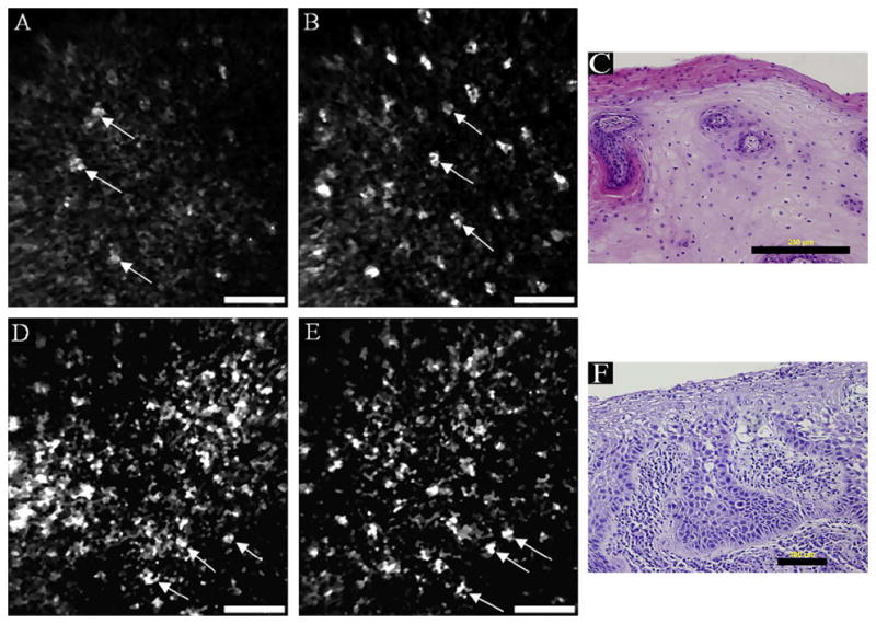
In vivo reflectance confocal endomicroscopy of normal oral mucosa on the ventral tongue (a–b) and moderate dysplasia on the floor of the mouth (d–e) with corresponding histology images (c, f). Scale bars: (a, b, d, e) 50 μm, (c) 200 μm, (f) 100 μm. Reprinted from Oral Oncology, 44(8), Maitland et al., p. 1059–1066, Copyright 2008, with permission from Elsevier.80
In vivo imaging of vocal cords is being explored by confocal endomicroscopy with potential to expand understanding of pediatric laryngeal development, currently limited by insufficient availability of pediatric laryngeal specimens.7 Preliminary imaging results with spectrally encoded confocal microscopy in porcine tissue demonstrate the potential for endomicroscopic imaging of the vocal folds. Images portraying epithelial cells, the basement membrane, and the lamina propria were obtained down to 375 μm deep in the tissue. Imaging and characterization of lesions is another potential application of confocal endomicroscopy of the vocal fold, where unnecessary removal of tissue should be minimized for voice preservation.49
Lung
A confocal fluorescence endomicroscope with spectral detection was used to image bronchial mucosa during a bronchoscopy procedure allowing a depth of focus of 50 μm below the surface.121 Twenty nine high risk patients for lung cancer had in vivo imaging and spectral analysis. The tracheobronchial tree was imaged and distinct patterns of the subepithelial fiber network were visible. All specimens diagnosed as histologically normal exhibited a similar pattern. In precancerous tissue, a decrease in intensity was seen as well as a disorganized fiber network within the bronchial wall.
Contained within the instrument channel of an endoscope, a confocal endomicroscope has the potential to distinguish normal bronchial epithelium from pre-neoplastic lesions in vivo.70 Cresyl violet was used as a contrast agent. Due to its acidic nature, which may be fatal to humans if administered in the lungs, the contrast agent was used with an altered pH for imaging of bronchial mucosa. Two bronchoscopes were used for the bronchoscopy and confocal endomicroscopy procedures, with the second one able to house a channel for the confocal endomicroscope. Normal epithelium exhibited uniformly distributed cells, while mild to moderate dysplasia displayed heterogeneous tissue architecture. Distal lung imaging is being explored via broncho-alveoscopy procedures.122 This is the first technique capable of imaging lobular and alveolar structures within the human lung.
Contrast Agents for Confocal Endomicroscopy
In order to achieve good imaging contrast within fluorescence confocal images, it is common to apply an exogenous contrast agent to the tissue. Currently, only a few contrast agents are frequently reported in the literature for in vivo use in humans for endomicroscopy: acetic acid, fluorescein sodium, acriflavine hydrocholoride, and cresyl violet.55, 70 Contrast agents approved for in vivo use for optical imaging by the United States Food and Drug Administration are acetic acid, fluorescein sodium, and indocyanine green.88, 124
Intravenous fluorescein sodium is most commonly used in the colon, esophagus, and stomach. Twenty seconds after injection of fluorescein, the agent is distributed throughout the tissue and can last 30 minutes allowing for imaging of 250 μm below the surface. It provides contrast in the connective tissue and, due to its intravenous administration and binding to serum albumin, contrast of the local microvasculature. Disruption to the vasculature, or leaky blood vessels, results in an increase in the overall fluorescence signal which may be indicative of disease. Fluorescein helps to visualize pit patterns in the colon, surface epithelial cells, connective tissue within the lamina propria, blood vessels, and red blood cells.28 Acriflavine hydrochloride, which is topically applied, is most commonly used in the stomach and colon. Acriflavine provides contrast between the nuclei and cytoplasm in the superficial epithelium for imaging of surface mucosa up to 100 μm. The combination of imaging modalities is common as information garnered with one modality may compliment another. However, it is desirable to limit the number of contrast agents needed for multi-modal imaging. Cresyl violet has proven to predict histology as a single topically applied contrast agent for in vivo confocal laser endomicroscopy and chromoendoscopy of the lower GI tract.34
In addition to these non-specific contrast agents, targeted molecular specific contrast agents have recently been developed for potential use in vivo to target biomarkers associated with certain diseases, such as cancer. For example, tumors can express unique receptors at a high rate. By targeting these biomarkers with high affinity ligands, it is possible to locate areas where carcinogenesis, angiogenesis, or metastasis is taking place.94 Both antibodies and peptides conjugated with exogenous dyes have been successfully used as specific binding contrast agents for optical imaging. Cyanine dyes conjugated to peptides have shown a three-fold increase in tumor contrast over normal tissue.4 Fluorescent signal is enhanced at the plasma membrane of the cells with increased receptor expression. A study using a targeted heptapeptide for colonic dysplasia was performed in vivo on patients undergoing colonoscopy.42 Confocal microendoscopy of the colon using the Cellvizio system by Mauna Kea Technologies exhibits images showing significant contrast at borders between normal and dysplastic crypts (Figure 6). Areas with dysplastic colonocytes show a higher fluorescent signal due to peptide binding in contrast to normal colonocytes.
Figure 6.
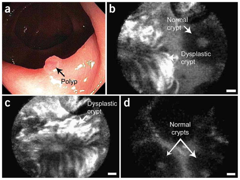
In vivo confocal fluorescence images of the border between colonic adenoma and normal mucosa, showing peptide binding to dysplastic colonocytes. (a) Endoscopic view, (b) border, (c) dysplastic crypt, and (d) adjacent mucosa. Scale bars: 20 μm. Reprinted by permission from Macmillan Publishers Ltd: Nature Medicine, 14(4), Hsiung et al., p. 454-458, Copyright 2008.42
Antibodies have been used to target the epidermal growth factor receptor (EGFR), a cell surface receptor that is over-expressed in many cancers. To aid early detection of oral neoplasia, oral biopsies were exposed to a monoclonal antibody specifically targeting EGFR.43 Abundant fluorescence signal was noted throughout abnormal mucosa. EGFR has also been targeted for imaging colorectal cancer in a mouse model.35 Two different human colorectal cancer cell lines were grown as tumors in mice. Using the Optiscan instrument by Pentax, the colon tumors were imaged in vivo after an injection of fluorescently labeled EGFR antibodies. Tumors with human cell lines expressing high levels of EGFR showed a distinctly higher signal when compared to tumors expressing low levels of EGFR. By targeting EGFR with fluorescently labeled antibodies, it was possible to differentiate between two types of human colorectal cancer tumors. To show the potential for in vivo use in humans, a similar study was performed on excised human tissue and the results indicated that it was possible to differentiate neoplastic from non-neoplastic tissues.
CONCLUSION
Major advances in the development of confocal endomicroscopes over the last few decades have enabled a new field of in vivo microscopic disease detection. We have presented how the technology has evolved over time, including the two primary commercially available endomicroscopy systems used in clinical studies. Further development should result in an enlargement of field of view and a reduction in overall probe size, while maintaining high resolution. Multi-scale and multi-modality systems, such as confocal endomicroscopy in combination with chromoendoscopy or fluorescence video-endoscopy, may improve detection or tissue classification.
Recent clinical evaluation for disease detection shows great promise for the future of this technology. Confocal endomicroscopy provides microscopic images of tissue with features that are similar to histology via “optical sectioning” of the tissue. It can be used to guide biopsy to a targeted site, reduce unnecessary biopsies, maximize diagnostic yield, and reduce morbidity of surgical treatments. Confocal endomicroscopy provides images and diagnostic information in real time, allowing on-the-fly decision making. It has been shown to have high sensitivity and specificity in comparison to traditional endoscopy techniques. In the future, confocal endomicroscopy may be explored for surgical margin detection and non-invasive monitoring of treatment. More extensive clinical trials will be required to fully prove the clinical utility to achieve widespread clinical adoption.
Acknowledgments
We gratefully acknowledge funding from NIH R01 CA138653.
References
- 1.Bajbouj M, Vieth M, Rosch T, Miehlke S, Becker V, Anders M, Pohl H, Madisch A, Schuster T, Schmid RM, Meining A. Probe-based confocal laser endomicroscopy compared with standard four-quadrant biopsy for evaluation of neoplasia in Barrett’s esophagus. Endoscopy. 2010;42:435–440. doi: 10.1055/s-0029-1244194. [DOI] [PubMed] [Google Scholar]
- 2.Bargiel S, Gorecki C, Verdot T, Laszczyk K, Albero J, El Fissi L. Electrostatically driven optical Z-axis scanner with thermally bonded glass microlens. Procedia Engineering. 2010;5:762–765. [Google Scholar]
- 3.Barretto RP, Messerschmidt B, Schnitzer MJ. In vivo fluorescence imaging with high-resolution microlenses. Nat Methods. 2009;6:511–512. doi: 10.1038/nmeth.1339. [DOI] [PMC free article] [PubMed] [Google Scholar]
- 4.Becker A, Hessenius C, Licha K, Ebert B, Sukowski U, Semmler W, Wiedenmann B, Grotzinger C. Receptor-targeted optical imaging of tumors with near-infrared fluorescent ligands. Nat Biotechnol. 2001;19:327–331. doi: 10.1038/86707. [DOI] [PubMed] [Google Scholar]
- 5.Benschop J, Vanrosmalen G. Confocal compact scanning optical microscope based on compact-disk technology. Appl Opt. 1991;30:1179–1184. doi: 10.1364/AO.30.001179. [DOI] [PubMed] [Google Scholar]
- 6.Boudoux C, Yun S, Oh W, White W, Iftimia N, Shishkov M, Bouma B, Tearney G. Rapid wavelength-swept spectrally encoded confocal microscopy. Opt Express. 2005;13:8214–8221. doi: 10.1364/opex.13.008214. [DOI] [PubMed] [Google Scholar]
- 7.Boudoux C, Leuin SC, Oh WY, Suter MJ, Desjardins AE, Vakoc BJ, Bouma BE, Hartnick CJ, Tearney GJ. Preliminary evaluation of noninvasive microscopic imaging techniques for the study of vocal fold development. J Voice. 2009;23:269–276. doi: 10.1016/j.jvoice.2007.10.003. [DOI] [PubMed] [Google Scholar]
- 8.Carlson K, Pavlova I, Collier T, Descour M, Follen M, Richards-Kortum R. Confocal microscopy: imaging cervical precancerous lesions. Gynecol Oncol. 2005;99:S84–S88. doi: 10.1016/j.ygyno.2005.07.049. [DOI] [PubMed] [Google Scholar]
- 9.Carlson KD, Chidley MD, Sung KB, Descour MR, Gillenwater A, Follen M, Richards-Kortum RR. In vivo fiber-optic confocal reflectance microscope with an injection-molded plastic miniature objective lens. Appl Opt. 2005;44:1792–1797. doi: 10.1364/ao.44.001792. [DOI] [PubMed] [Google Scholar]
- 10.Cavanagh HD, Petroll WM, Jester JV. The application of confocal microscopy to the study of living systems. Neurosci Biobehav Rev. 1993;17:483–498. doi: 10.1016/s0149-7634(05)80127-7. [DOI] [PubMed] [Google Scholar]
- 11.Chidley MD, Carlson KD, Richards-Kortum RR, Descour MR. Design, assembly, and optical bench testing of a high-numerical-aperture miniature injection-molded objective for fiber-optic confocal reflectance microscopy. Appl Opt. 2006;45:2545–2554. doi: 10.1364/ao.45.002545. [DOI] [PubMed] [Google Scholar]
- 12.Collier T, Smithpeter C, Cowman B, Drezek R, Descour M, Richards–Kortum R. Fiber-optic confocal microscope for biological imaging. Conference on Lasers and Electro-Optics: OSA; 1998. pp. 128–129. [Google Scholar]
- 13.Corcuff P, Leveque JL. In vivo vision of the human skin with the tandem scanning microscope. Dermatology. 1993;186:50–54. doi: 10.1159/000247302. [DOI] [PubMed] [Google Scholar]
- 14.Dabbs T, Glass M. Fiber-optic confocal microscope: FOCON. Appl Opt. 1992;31:3030–3035. doi: 10.1364/AO.31.003030. [DOI] [PubMed] [Google Scholar]
- 15.Delaney PM, Harris MR, King RG. Fiber-optic laser scanning confocal microscope suitable for fluorescence imaging. Appl Opt. 1994;33:573–577. doi: 10.1364/AO.33.000573. [DOI] [PubMed] [Google Scholar]
- 16.Delaney PM, King RG, Lambert JR, Harris MR. Fiber optic confocal imaging (FOCI) for subsurface microscopy of the colon in vivo. J Anat. 1994;184:157–160. [PMC free article] [PubMed] [Google Scholar]
- 17.Dickensheets DL, Kino GS. Scanned optical fiber confocal microscope. Proc. SPIE; 1994. pp. 39–47. [Google Scholar]
- 18.Dickensheets DL, Kino GS. Micromachined scanning confocal optical microscope. Opt Lett. 1996;21:764–766. doi: 10.1364/ol.21.000764. [DOI] [PubMed] [Google Scholar]
- 19.Dickensheets DL, Kino GS. Silicon-micromachined scanning confocal optical microscope. J Microelectromech S. 1998;7:38–47. doi: 10.1364/ol.21.000764. [DOI] [PubMed] [Google Scholar]
- 20.Dickensheets DL. Requirements of MEMS membrane mirrors for focus adjustment and aberration correction in endoscopic confocal and optical coherence tomography imaging instruments. J Micro-Nanolith MEM. 2008;7:021008. [Google Scholar]
- 21.Drezek RA, Collier T, Brookner CK, Malpica A, Lotan R, Richards-Kortum RR, Follen M. Laser scanning confocal microscopy of cervical tissue before and after application of acetic acid. Am J Obstet Gynecol. 2000;182:1135–1139. doi: 10.1067/mob.2000.104844. [DOI] [PubMed] [Google Scholar]
- 22.Dunbar K, Canto M. Confocal endomicroscopy. Curr Opin Gastroen. 2008;24:631–637. doi: 10.1097/MOG.0b013e32830c91c7. [DOI] [PubMed] [Google Scholar]
- 23.Engelbrecht CJ, Johnston RS, Seibel EJ, Helmchen F. Ultra-compact fiber-optic two-photon microscope for functional fluorescence imaging in vivo. Opt Express. 2008;16:5556–5564. doi: 10.1364/oe.16.005556. [DOI] [PubMed] [Google Scholar]
- 24.Farahati B, Stachs O, Prall F, Stave J, Guthoff R, Pau HW, Just T. Rigid confocal endoscopy for in vivo imaging of experimental oral squamous intra-epithelial lesions. J Oral Pathol Med. 2010;39:318–327. doi: 10.1111/j.1600-0714.2009.00841.x. [DOI] [PubMed] [Google Scholar]
- 25.Feng Z, Wang L, Duan H. Confocal fluorescence microendoscopy using a digital micro-mirror device. Proc. SPIE - Optics in Health Care and Biomedical Optics IV; Beijing, China: SPIE; 2010. p. 78451M. [Google Scholar]
- 26.Flusberg BA, Cocker ED, Piyawattanametha W, Jung JC, Cheung EL, Schnitzer MJ. Fiber-optic fluorescence imaging. Nat Methods. 2005;2:941–950. doi: 10.1038/nmeth820. [DOI] [PMC free article] [PubMed] [Google Scholar]
- 27.Flusberg BA, Jung JC, Cocker ED, Anderson EP, Schnitzer MJ. In vivo brain imaging using a portable 3.9 gram two-photon fluorescence microendoscope. Opt Lett. 2005;30:2272–2274. doi: 10.1364/ol.30.002272. [DOI] [PubMed] [Google Scholar]
- 28.Gheonea DI, Saftoiu A, Ciurea T, Popescu C, Georgescu CV, Malos A. Confocal laser endomicroscopy of the colon. J Gastrointestin Liver Dis. 2010;19:207–211. [PubMed] [Google Scholar]
- 29.Gillenwater A, Papadimitrakopoulou V, Richards-Kortum R. Oral premalignancy: new methods of detection and treatment. Curr Oncol Rep. 2006;8:146–154. doi: 10.1007/s11912-006-0050-4. [DOI] [PMC free article] [PubMed] [Google Scholar]
- 30.Giniūnas L, Juškaitis R, Shatalin SV. Scanning fibre-optic microscope. Electron Lett. 1991;27:724–726. [Google Scholar]
- 31.Giniūnas L, Juškaitis R, Shatalin SV. Endoscope with optical sectioning capability. Appl Opt. 1993;32:2888–2890. doi: 10.1364/AO.32.002888. [DOI] [PubMed] [Google Scholar]
- 32.Gmitro AF, Aziz D. Confocal microscopy through a fiber-optic imaging bundle. Opt Lett. 1993;18:565–567. doi: 10.1364/ol.18.000565. [DOI] [PubMed] [Google Scholar]
- 33.Gmitro AF, Rouse AR. Development and use of a confocal microendoscope for in vivo histopathologic diagnosis. Proc. SPIE - Biomedical Diagnostic, Guidance, and Surgical-Assist Systems III; San Jose, CA, USA: SPIE; 2001. pp. 41–48. [Google Scholar]
- 34.Goetz M, Toermer T, Vieth M, Dunbar K, Hoffman A, Galle PR, Neurath MF, Delaney P, Kiesslich R. Simultaneous confocal laser endomicroscopy and chromoendoscopy with topical cresyl violet. Gastrointest Endosc. 2009;70:959–968. doi: 10.1016/j.gie.2009.04.016. [DOI] [PubMed] [Google Scholar]
- 35.Goetz M, Ziebart A, Foersch S, Vieth M, Waldner MJ, Delaney P, Galle PR, Neurath MF, Kiesslich R. In vivo molecular imaging of colorectal cancer with confocal endomicroscopy by targeting epidermal growth factor receptor. Gastroenterology. 2010;138:435–446. doi: 10.1053/j.gastro.2009.10.032. [DOI] [PubMed] [Google Scholar]
- 36.Gu M, Sheppard CJR, Gan X. Image formation in a fiber-optical confocal scanning microscope. J Opt Soc Am A. 1991;8:1755–1761. [Google Scholar]
- 37.Haxel BR, Goetz M, Kiesslich R, Gosepath J. Confocal endomicroscopy: a novel application for imaging of oral and oropharyngeal mucosa in human. Eur Arch Otorhinolaryngol. 2010;267:443–448. doi: 10.1007/s00405-009-1035-3. [DOI] [PubMed] [Google Scholar]
- 38.Helmchen F, Fee MS, Tank DW, Denk W. A miniature head-mounted two-photon microscope: high-resolution brain imaging in freely moving animals. Neuron. 2001;31:903–912. doi: 10.1016/s0896-6273(01)00421-4. [DOI] [PubMed] [Google Scholar]
- 39.Hendriks BHW, Bierhoff WCJ, Horikx JJL, Desjardins AE, Hezemans CA, W‘t Hooft G, Lucassen GW, Mihajlovic N. High-resolution resonant and nonresonant fiber-scanning confocal microscope. J Biomed Opt. 2011;16:026007. doi: 10.1117/1.3534781. [DOI] [PubMed] [Google Scholar]
- 40.Hofmann U, Muehlmann S, Witt M, Doerschel K, Schuetz R, Wagner B. Proc SPIE - Miniaturized Systems with Micro-Optics and MEMS. Santa Clara, CA, USA: SPIE; 1999. Electrostatically driven micromirrors for a miniaturized confocal laser scanning microscope; pp. 29–38. [Google Scholar]
- 41.Howlader N, Noone AM, Krapcho M, Neyman N, Aminou R, Waldron W, Altekruse SF, Kosary CL, Ruhl J, Tatalovich Z, Cho H, Mariotto A, Eisner MP, Lewis DR, Chen HS, Feuer EJ, Cronin KA, Edwards BK. Based on November 2010 SEER data submission, posted to the SEER web site, 2011. National Cancer Institute; Bethesda, MD: SEER Cancer Statistics Review, 1975–2008. [Google Scholar]
- 42.Hsiung PL, Hardy J, Friedland S, Soetikno R, Du CB, Wu AP, Sahbaie P, Crawford JM, Lowe AW, Contag CH, Wang TD. Detection of colonic dysplasia in vivo using a targeted heptapeptide and confocal microendoscopy. Nat Med. 2008;14:454–458. doi: 10.1038/nm1692. [DOI] [PMC free article] [PubMed] [Google Scholar]
- 43.Hsu ER, Gillenwater AM, Hasan MQ, Williams MD, El-Naggar AK, Richards-Kortum RR. Real-time detection of epidermal growth factor receptor expression in fresh oral cavity biopsies using a molecular-specific contrast agent. Int J Cancer. 2006;118:3062–71. doi: 10.1002/ijc.21720. [DOI] [PubMed] [Google Scholar]
- 44.Jester JV, Andrews PM, Petroll WM, Lemp MA, Cavanagh HD. In vivo, real-time confocal imaging. J Electron Microsc Tech. 1991;18:50–60. doi: 10.1002/jemt.1060180108. [DOI] [PubMed] [Google Scholar]
- 45.Jung JC, Mehta AD, Aksay E, Stepnoski R, Schnitzer MJ. In vivo mammalian brain imaging using one- and two-photon fluorescence microendoscopy. J Neurophysiol. 2004;92:3121–3133. doi: 10.1152/jn.00234.2004. [DOI] [PMC free article] [PubMed] [Google Scholar]
- 46.Juškaitis R, Reinholz F, Wilson T. Fibre-optic based confocal scanning microscopy with semiconductor laser excitation and detection. Electron Lett. 1992;28:986–988. [Google Scholar]
- 47.Juškaitis R, Wilson T. Direct-view fiberoptic confocal microscope. Opt Lett. 1994;19:1906–1908. doi: 10.1364/ol.19.001906. [DOI] [PubMed] [Google Scholar]
- 48.Juškaitis R, Wilson T, Watson TF. Real-time white light reflection confocal microscopy using a fibre-optic bundle. Scanning. 1997;19:15–19. [Google Scholar]
- 49.Just T, Stave J, Boltze C, Wree A, Kramp B, Guthoff RF, Pau HW. Laser scanning microscopy of the human larynx mucosa: A preliminary, ex vivo study. Laryngoscope. 2006;116:1136–1141. doi: 10.1097/01.mlg.0000217529.53079.59. [DOI] [PubMed] [Google Scholar]
- 50.Kakeji Y, Yamaguchi S, Yoshida D, Tanoue K, Ueda M, Masunari A, Utsunomiya T, Imamura M, Honda H, Maehara Y, Hashizume M. Development and assessment of morphologic criteria for diagnosing gastric cancer using confocal endomicroscopy: an ex vivo and in vivo study. Endoscopy. 2006;38:886–890. doi: 10.1055/s-2006-944735. [DOI] [PubMed] [Google Scholar]
- 51.Kester RT, Tkaczyk TS, Descour MR, Christenson T, Richards-Kortum R. High numerical aperture microendoscope objective for a fiber confocal reflectance microscope. Opt Express. 2007;15:2409–2420. doi: 10.1364/oe.15.002409. [DOI] [PubMed] [Google Scholar]
- 52.Kester RT, Christenson T, Richards-Kortum R, Tkaczyk TS. Low cost, high performance, self-aligning miniature optical systems. Appl Opt. 2009;48:3375–3384. doi: 10.1364/ao.48.003375. [DOI] [PMC free article] [PubMed] [Google Scholar]
- 53.Kiesslich R, Burg J, Vieth M, Gnaendiger J, Enders M, Delaney P, Polglase A, McLaren W, Janell D, Thomas S, Nafe B, Galle PR, Neurath MF. Confocal laser endoscopy for diagnosing intraepithelial neoplasias and colorectal cancer in vivo. Gastroenterology. 2004;127:706–713. doi: 10.1053/j.gastro.2004.06.050. [DOI] [PubMed] [Google Scholar]
- 54.Kiesslich R, Goetz M, Burg J, Stolte M, Siegel E, Maeurer MJ, Thomas S, Strand D, Galle PR, Neurath MF. Diagnosing Helicobacter pylori in vivo by confocal laser endoscopy. Gastroenterology. 2005;128:2119–2123. doi: 10.1053/j.gastro.2004.12.035. [DOI] [PubMed] [Google Scholar]
- 55.Kiesslich R, Goetz M, Vieth M, Galle PR, Neurath MF. Confocal laser endomicroscopy. Gastrointest Endosc Clin N Am. 2005;15:715–731. doi: 10.1016/j.giec.2005.08.010. [DOI] [PubMed] [Google Scholar]
- 56.Kiesslich R, Gossner L, Goetz M, Dahlmann A, Vieth M, Stolte M, Hoffman A, Jung M, Nafe B, Galle PR, Neurath MF. In vivo histology of Barrett’s esophagus and associated neoplasia by confocal laser endomicroscopy. Clin Gastroenterol Hepatol. 2006;4:979–987. doi: 10.1016/j.cgh.2006.05.010. [DOI] [PubMed] [Google Scholar]
- 57.Kim P, Puoris’haag M, Cote D, Lin CP, Yun SH. In vivo confocal and multiphoton microendoscopy. J Biomed Opt. 2008;13:010501. doi: 10.1117/1.2839043. [DOI] [PMC free article] [PubMed] [Google Scholar]
- 58.Kim P, Chung E, Yamashita H, Hung KE, Mizoguchi A, Kucherlapati R, Fukumura D, Jain RK, Yun SH. In vivo wide-area cellular imaging by side-view endomicroscopy. Nat Methods. 2010;7:303–305. doi: 10.1038/nmeth.1440. [DOI] [PMC free article] [PubMed] [Google Scholar]
- 59.Kim Y-D, Ahn M, Gweon D-G. Proc SPIE - Endoscopic Microscopy V. San Francisco, CA, USA: SPIE; 2010. Design of small confocal endo-microscopic probe working under multi-wavelength environment; p. 75580S. [Google Scholar]
- 60.Kimura S, Wilson T. Confocal scanning optical microscope using single-mode fiber for signal detection. Appl Opt. 1991;30:2143–2150. doi: 10.1364/AO.30.002143. [DOI] [PubMed] [Google Scholar]
- 61.Kitabatake S, Niwa Y, Miyahara R, Ohashi A, Matsuura T, Iguchi Y, Shimoyama Y, Nagasaka T, Maeda O, Ando T, Ohmiya N, Itoh A, Hirooka Y, Goto H. Confocal endomicroscopy for the diagnosis of gastric cancer in vivo. Endoscopy. 2006;38:1110–1114. doi: 10.1055/s-2006-944855. [DOI] [PubMed] [Google Scholar]
- 62.Knittel J, Schnieder L, Buess G, Messerschmidt B, Possner T. Endoscope-compatible confocal microscope using a gradient index-lens system. Opt Commun. 2001;188:267–273. [Google Scholar]
- 63.Koester CJ, Auran JD, Rosskothen HD, Florakis GJ, Tackaberry RB. Clinical microscopy of the cornea utilizing optical sectioning and a high-numerical-aperture objective. J Opt Soc Am A. 1993;10:1670–1679. doi: 10.1364/josaa.10.001670. [DOI] [PubMed] [Google Scholar]
- 64.Kumar K, Avritscher R, Wang YM, Lane N, Madoff DC, Yu TK, Uhr JW, Zhang XJ. Handheld histology-equivalent sectioning laser-scanning confocal optical microscope for interventional imaging. Biomed Microdevices. 2010;12:223–233. doi: 10.1007/s10544-009-9377-6. [DOI] [PubMed] [Google Scholar]
- 65.Kwon S, Lee LP. Micromachined transmissive scanning confocal microscope. Opt Lett. 2004;29:706–708. doi: 10.1364/ol.29.000706. [DOI] [PubMed] [Google Scholar]
- 66.Laemmel E, Genet M, Le Goualher G, Perchant A, Le Gargasson JF, Vicaut E. Fibered confocal fluorescence microscopy (Cell-viZio TM) facilitates extended imaging in the field of microcirculation. J Vasc Res. 2004;41:400–411. doi: 10.1159/000081209. [DOI] [PubMed] [Google Scholar]
- 67.Landau SM, Liang C, Kester RT, Tkaczyk TS, Descour MR. Design and evaluation of an ultra-slim objective for in-vivo deep optical biopsy. Opt Express. 2010;18:4758–4775. doi: 10.1364/OE.18.004758. [DOI] [PMC free article] [PubMed] [Google Scholar]
- 68.Lane PM, Dlugan ALP, Richards-Kortum R, MacAulay CE. Fiber-optic confocal microscopy using a spatial light modulator. Opt Lett. 2000;25:1780–1782. doi: 10.1364/ol.25.001780. [DOI] [PubMed] [Google Scholar]
- 69.Lane PM, Elliott RP, MacAulay CE. Confocal microendoscopy with chromatic sectioning. Proc. SPIE - Spectral Imaging: Instrumentation, Applications, and Analysis II; San Jose, CA, USA: SPIE; 2003. pp. 23–26. [Google Scholar]
- 70.Lane PM, Lam S, McWilliams A, Le Riche JC, Anderson MW, MacAulay CE. Confocal fluorescence microendoscopy of bronchial epithelium. J Biomed Opt. 2009;14:024008. doi: 10.1117/1.3103583. [DOI] [PubMed] [Google Scholar]
- 71.Le Goualher G, Perchant A, Genet M, Cave C, Viellerobe B, Berier F, Abrat B, Ayache N. Towards optical biopsies with an integrated fibered confocal fluorescence microscope. Part II Proceedings of the 7th International Conference on Medical Image Computing and Computer-Assisted Intervention; Saint-Malo, France. 2004. pp. 761–768. [Google Scholar]
- 72.Leong RW, Nguyen NQ, Meredith CG, Al-Sohaily S, Kukic D, Delaney PM, Murr ER, Yong J, Merrett ND, Biankin AV. In vivo confocal endomicroscopy in the diagnosis and evaluation of celiac disease. Gastroenterology. 2008;135:1870–1876. doi: 10.1053/j.gastro.2008.08.054. [DOI] [PubMed] [Google Scholar]
- 73.Liang C, Descour MR, Sung KB, Richards-Kortum R. Fiber confocal reflectance microscope (FCRM) for in-vivo imaging. Opt Express. 2001;9:821–830. doi: 10.1364/oe.9.000821. [DOI] [PubMed] [Google Scholar]
- 74.Liang C, Sung KB, Richards-Kortum RR, Descour MR. Design of a high-numerical-aperture miniature microscope objective for an endoscopic fiber confocal reflectance microscope. Appl Opt. 2002;41:4603–4610. doi: 10.1364/ao.41.004603. [DOI] [PubMed] [Google Scholar]
- 75.Lin CP, Webb RH. Fiber-coupled multiplexed confocal microscope. Opt Lett. 2000;25:954–956. doi: 10.1364/ol.25.000954. [DOI] [PubMed] [Google Scholar]
- 76.Liu JTC, Mandella MJ, Ra H, Wong LK, Solgaard O, Kino GS, Piyawattanametha W, Contag CH, Wang TD. Miniature near-infrared dual-axes confocal microscope utilizing a two-dimensional microelectromechanical systems scanner. Opt Lett. 2007;32:256–258. doi: 10.1364/ol.32.000256. [DOI] [PMC free article] [PubMed] [Google Scholar]
- 77.Liu JTC, Loewke NO, Mandella MJ, Levenson RM, Crawford JM, Contag CH. Point-of-care pathology with miniature microscopes. Anal Cell Pathol. 2011;34:81–98. doi: 10.3233/ACP-2011-011. [DOI] [PMC free article] [PubMed] [Google Scholar]
- 78.Luck BL, Carlson KD, Bovik AC, Richards-Kortum RR. An image model and segmentation algorithm for reflectance confocal images of in vivo cervical tissue. IEEE Trans Image Proc. 2005;14:1265–1276. doi: 10.1109/tip.2005.852460. [DOI] [PubMed] [Google Scholar]
- 79.Maitland KC, Shin HJ, Ra H, Lee D, Solgaard O, Richards-Kortum R. Single fiber confocal microscope with a two-axis gimbaled MEMS scanner for cellular imaging. Opt Express. 2006;14:8604–8612. doi: 10.1364/oe.14.008604. [DOI] [PubMed] [Google Scholar]
- 80.Maitland KC, Gillenwater AM, Williams MD, El-Naggar AK, Descour MR, Richards-Kortum RR. In vivo imaging of oral neoplasia using a miniaturized fiber optic confocal reflectance microscope. Oral Oncol. 2008;44:1059–1066. doi: 10.1016/j.oraloncology.2008.02.002. [DOI] [PMC free article] [PubMed] [Google Scholar]
- 81.Meining A, Saur D, Bajbouj M, Becker V, Peltier E, Hoefler H, Von Weyhern CH, Schmid RM, Prinz C. In vivo histopathology for detection of gastrointestinal neoplasia with a portable, Confocal miniprobe: An examiner blinded analysis. Clin Gastroenterol H. 2007;5:1261–1267. doi: 10.1016/j.cgh.2007.05.019. [DOI] [PubMed] [Google Scholar]
- 82.Minsky M. Memoir on inventing the confocal scanning microscope. Scanning. 1988;10:128–138. [Google Scholar]
- 83.Moghimi MJ, Lutzenberger BJ, Kaylor BM, Dickensheets DL. MOEMS deformable mirrors for focus control in vital microscopy. J Micro-Nanolith MEM. 2011;10:023005. [Google Scholar]
- 84.Murakami K, Murata A, Suga T, Kitagawa H, Kamiya Y, Kubo M, Matsumoto K, Miyajima H, Katashiro M. A miniature confocal optical microscope with MEMS gimbal scanner. Proceedings of the 12th International Conference on TRANSDUCERS, Solid-State Sensor, Actuators and Microsystems; Boston, MA, USA. 2003. pp. 587–590. [Google Scholar]
- 85.Murakami K. A miniature confocal optical scanning microscope for endoscope. Proc. SPIE -MOEMS Display and Imaging Systems III; San Jose, CA, USA: SPIE; 2005. pp. 119–131. [Google Scholar]
- 86.Myaing MT, MacDonald DJ, Li X. Fiber-optic scanning two-photon fluorescence endoscope. Opt Lett. 2006;31:1076–1078. doi: 10.1364/ol.31.001076. [DOI] [PubMed] [Google Scholar]
- 87.Nakao M, Yoshida S, Tanaka S, Takemura Y, Oka S, Yoshihara M, Chayama K. Optical biopsy of early gastroesophageal cancer by catheter-based reflectance-type laser-scanning confocal microscopy. J Biomed Opt. 2008;13:054043. doi: 10.1117/1.2983674. [DOI] [PubMed] [Google Scholar]
- 88.National Library of Medicine (US) National Center for Biotechnology Information. Molecular Imaging and Contrast Agent Database (MICAD) 2011 Available from: http://micad.nih.gov. [PubMed]
- 89.New KC, Petroll WM, Boyde A, Martin L, Corcuff P, Leveque JL, Lemp MA, Cavanagh HD, Jester JV. In vivo imaging of human teeth and skin using real-time confocal microscopy. Scanning. 1991;13:369–372. [Google Scholar]
- 90.Osdoit A, Lacombe F, Cave C, Loiseau S, Peltier E. To see... the unseeable: confocal miniprobes for routine microscopic imaging during endoscopy. Proc. SPIE - Endoscopic Microscopy II; San Jose, CA, USA. 2007. p. 64320F. [Google Scholar]
- 91.Ota T, Fukuyama H, Ishihara Y, Tanaka H, Takamatsu T. In situ fluorescence imaging of organs through compact scanning head for confocal laser microscopy. J Biomed Opt. 2005;10:024010. doi: 10.1117/1.1890411. [DOI] [PubMed] [Google Scholar]
- 92.Petran M, Hadravsky M, Benes J, Boyde A. In vivo microscopy using the tandem scanning microscope. Ann N Y Acad Sci. 1986;483:440–447. doi: 10.1111/j.1749-6632.1986.tb34554.x. [DOI] [PubMed] [Google Scholar]
- 93.Petroll WM, Jester JV, Cavanagh HD. In vivo confocal imaging: general principles and applications. Scanning. 1994;16:131–149. [PubMed] [Google Scholar]
- 94.Pierce MC, Javier DJ, Richards-Kortum R. Optical contrast agents and imaging systems for detection and diagnosis of cancer. Int J Cancer. 2008;123:1979–1990. doi: 10.1002/ijc.23858. [DOI] [PMC free article] [PubMed] [Google Scholar]
- 95.Pillai RS, Lorenser D, Sampson DD. Deep-tissue access with confocal fluorescence microendoscopy through hypodermic needles. Opt Express. 2011;19:7213–7221. doi: 10.1364/OE.19.007213. [DOI] [PubMed] [Google Scholar]
- 96.Pitris C, Bouma BE, Shiskov M, Tearney GJ. A GRISM-based probe for spectrally encoded confocal microscopy. Opt Express. 2003;11:120–124. doi: 10.1364/oe.11.000120. [DOI] [PubMed] [Google Scholar]
- 97.Piyawattanametha W, Ra H, Mandella MJ, Loewke K, Wang TD, Kino GS, Solgaard O, Contag CH. 3-D near-infrared fluorescence imaging using an MEMS-based miniature dual-axis confocal microscope. IEEE J Sel Top Quant. 2009;15:1344–1350. [Google Scholar]
- 98.Poland SP, Li L, Uttamchandani D, Girkin JM. A confocal micro-imaging system incorporating a thermally actuated two axis MEMS scanner. Proc. SPIE - Endoscopic Microscopy IV; San Jose, CA, USA: SPIE; 2009. pp. 717203–717209. [Google Scholar]
- 99.Polglase A, McLaren WJ, Skinner SA, Kiesslich R, Neurath MF, Delaney PM. A fluorescence confocal endomicroscope for in vivo microscopy of the upper- and lower-GI tract. Gastrointest Endosc. 2005;62:686–695. doi: 10.1016/j.gie.2005.05.021. [DOI] [PubMed] [Google Scholar]
- 100.Ra HJ, Piyawattanametha W, Mandella MJ, Hsiung PL, Hardy J, Wang TD, Contag CH, Kino GS, Solgaard O. Three-dimensional in vivo imaging by a handheld dual-axes confocal microscope. Opt Express. 2008;16:7224–7232. doi: 10.1364/oe.16.007224. [DOI] [PMC free article] [PubMed] [Google Scholar]
- 101.Rajadhyaksha M, Grossman M, Esterowitz D, Webb RH, Anderson RR. In vivo confocal scanning laser microscopy of human skin: melanin provides strong contrast. J Invest Dermatol. 1995;104:946–952. doi: 10.1111/1523-1747.ep12606215. [DOI] [PubMed] [Google Scholar]
- 102.Rajadhyaksha M, Anderson RR, Webb RH. Video-rate confocal scanning laser microscope for imaging human tissues in vivo. Appl Opt. 1999;38:2105–2115. doi: 10.1364/ao.38.002105. [DOI] [PubMed] [Google Scholar]
- 103.Rajadhyaksha M, Gonzalez S, Zavislan JM, Anderson RR, Webb RH. In vivo confocal scanning laser microscopy of human skin II: advances in instrumentation and comparison with histology. J Invest Dermatol. 1999;113:293–303. doi: 10.1046/j.1523-1747.1999.00690.x. [DOI] [PubMed] [Google Scholar]
- 104.Rouse AR, Gmitro AF. Multispectral imaging with a confocal microendoscope. Opt Lett. 2000;25:1708–1710. doi: 10.1364/ol.25.001708. [DOI] [PubMed] [Google Scholar]
- 105.Rouse AR, Kano A, Gmitro AF. Development of a fiber-optic confocal microendoscope for clinical endoscopy. Proc. SPIE - Optical Biopsy IV; San Jose, CA, USA: SPIE; 2002. pp. 244–253. [Google Scholar]
- 106.Rouse AR, Kano A, Udovich JA, Kroto SM, Gmitro AF. Design and demonstration of a miniature catheter for a confocal microendoscope. Appl Opt. 2004;43:5763–5771. doi: 10.1364/ao.43.005763. [DOI] [PubMed] [Google Scholar]
- 107.Sabharwal YS, Rouse AR, Donaldson L, Hopkins MF, Gmitro AF. Slit-scanning confocal microendoscope for high-resolution in vivo imaging. Appl Opt. 1999;38:7133–7144. doi: 10.1364/ao.38.007133. [DOI] [PubMed] [Google Scholar]
- 108.Sakashita M, Inoue H, Kashida H, Tanaka J, Cho JY, Satodate H, Hidaka E, Yoshida T, Fukami N, Tamegai Y, Shiokawa A, Kudo S. Virtual histology of colorectal lesions using laser-scanning confocal microscopy. Endoscopy. 2003;35:1033–1038. doi: 10.1055/s-2003-44595. [DOI] [PubMed] [Google Scholar]
- 109.Shin HJ, Pierce MC, Lee D, Ra H, Solgaard O, Richards-Kortum R. Fiber-optic confocal microscope using a MEMS scanner and miniature objective lens. Opt Express. 2007;15:9113–9122. doi: 10.1364/oe.15.009113. [DOI] [PubMed] [Google Scholar]
- 110.Sokolov K, Sung KB, Collier T, Clark A, Arifler D, Lacy A, Descour M, Richards-Kortum R. Endoscopic microscopy. Dis Markers. 2002;18:269–291. doi: 10.1155/2002/251264. [DOI] [PMC free article] [PubMed] [Google Scholar]
- 111.Sonn GA, Jones SN, Tarin TV, Du CB, Mach KE, Jensen KC, Liao JC. Optical biopsy of human bladder neoplasia with in vivo confocal laser endomicroscopy. J Urol. 2009;182:1299–1305. doi: 10.1016/j.juro.2009.06.039. [DOI] [PubMed] [Google Scholar]
- 112.Sung KB, Liang C, Descour M, Collier T, Follen M, Malpica A, Richards-Kortum R. Near real time in vivo fibre optic confocal microscopy: sub-cellular structure resolved. J Microsc-Oxford. 2002;207:137–145. doi: 10.1046/j.1365-2818.2002.01049.x. [DOI] [PubMed] [Google Scholar]
- 113.Sung KB, Liang C, Descour M, Collier T, Follen M, Richards-Kortum R. Fiber-optic confocal reflectance microscope with miniature objective for in vivo imaging of human tissues. IEEE T Bio-Med Eng. 2002;49:1168–1172. doi: 10.1109/TBME.2002.803524. [DOI] [PubMed] [Google Scholar]
- 114.Sung KB, Richards-Kortum R, Follen M, Malpica A, Liang C, Descour M. Fiber optic confocal reflectance microscopy: a new real-time technique to view nuclear morphology in cervical squamous epithelium in vivo. Opt Express. 2003;11:3171–3181. doi: 10.1364/oe.11.003171. [DOI] [PubMed] [Google Scholar]
- 115.Tan J, Quinn MA, Pyman JM, Delaney PM, McLaren WJ. Detection of cervical intraepithelial neoplasia in vivo using confocal endomicroscopy. BJOG. 2009;116:1663–1670. doi: 10.1111/j.1471-0528.2009.02261.x. [DOI] [PubMed] [Google Scholar]
- 116.Tanbakuchi AA, Rouse AR, Udovich JA, Gmitro AF. Surgical imaging catheter for confocal microendoscopy with advanced contrast delivery and focus systems. Proc. SPIE - Endoscopic Microscopy; San Jose, CA, USA: SPIE; 2006. p. 608202. [Google Scholar]
- 117.Tanbakuchi AA, Rouse AR, Udovich JA, Hatch KD, Gmitro AF. Clinical confocal microlaparoscope for real-time in vivo optical biopsies. J Biomed Opt. 2009;14:044030. doi: 10.1117/1.3207139. [DOI] [PMC free article] [PubMed] [Google Scholar]
- 118.Tanbakuchi AA, Udovich JA, Rouse AR, Hatch KD, Gmitro AF. In vivo imaging of ovarian tissue using a novel confocal microlaparoscope. Am J Obstet Gynecol. 2010;202:90.e1–90.e9. doi: 10.1016/j.ajog.2009.07.027. [DOI] [PMC free article] [PubMed] [Google Scholar]
- 119.Tearney GJ, Webb RH, Bouma BE. Spectrally encoded confocal microscopy. Opt Lett. 1998;23:1152–1154. doi: 10.1364/ol.23.001152. [DOI] [PubMed] [Google Scholar]
- 120.Tearney GJ, Shishkov M, Bouma BE. Spectrally encoded miniature endoscopy. Opt Lett. 2002;27:412–414. doi: 10.1364/ol.27.000412. [DOI] [PubMed] [Google Scholar]
- 121.Thiberville L, Moreno-Swirc S, Vercauteren T, Peltier E, Cave C, Heckly GB. In vivo imaging of the bronchial wall microstructure using fibered confocal fluorescence microscopy. Am J Respir Crit Care Med. 2007;175:22–37. doi: 10.1164/rccm.200605-684OC. [DOI] [PubMed] [Google Scholar]
- 122.Thiberville L, Salaun M, Lachkar S, Dominique S, Moreno-Swirc S, Vever-Bizet C, Bourg-Heckly G. Confocal fluorescence endomicroscopy of the human airways. Proc Am Thorac Soc. 2009;6:444–449. doi: 10.1513/pats.200902-009AW. [DOI] [PubMed] [Google Scholar]
- 123.Thompson AJ, Paterson C, Neil MAA, Dunsby C, French PMW. Adaptive phase compensation for ultracompact laser scanning endomicroscopy. Opt Lett. 2011;36:1707–1709. doi: 10.1364/OL.36.001707. [DOI] [PubMed] [Google Scholar]
- 124.U.S. Food and Drug Administration. Drugs@FDA: FDA Approved Drug Products. 2011 Available from: http://www.accessdata.fda.gov/scripts/cder/drugsatfda/index.cfm.
- 125.Viellerobe B, Osdoit A, Cave C, Lacombe F, Loiseau S, Abrat B. Mauna Kea technologies’ F400 prototype: a new tool for in vivo microscopic imaging during endoscopy. Proc. SPIE - Endoscopic Microscopy; San Jose, CA, USA. 2006. p. 60820C. [Google Scholar]
- 126.Wang TD, Contag CH, Mandella MJ, Chan NY, Kino GS. Dual-axes confocal microscopy with post-objective scanning and low-coherence heterodyne detection. Opt Lett. 2003;28:1915–1917. doi: 10.1364/ol.28.001915. [DOI] [PMC free article] [PubMed] [Google Scholar]
- 127.Wang TD, Mandella MJ, Contag CH, Kino GS. Dual-axis confocal microscope for high-resolution in vivo imaging. Opt Lett. 2003;28:414–416. doi: 10.1364/ol.28.000414. [DOI] [PMC free article] [PubMed] [Google Scholar]
- 128.Watanabe O, Ando T, Maeda O, Hasegawa M, Ishikawa D, Ishiguro K, Ohmiya N, Niwa Y, Goto H. Confocal endomicroscopy in patients with ulcerative colitis. J Gastroenterol Hepatol. 2008;23(Suppl 2):S286–S290. doi: 10.1111/j.1440-1746.2008.05559.x. [DOI] [PubMed] [Google Scholar]
- 129.White WM, Rajadhyaksha M, Gonzalez S, Fabian RL, Anderson RR. Noninvasive imaging of human oral mucosa in vivo by confocal reflectance microscopy. Laryngoscope. 1999;109:1709–1717. doi: 10.1097/00005537-199910000-00029. [DOI] [PubMed] [Google Scholar]
- 130.Wilson BC. Detection and treatment of dysplasia in Barrett’s esophagus: a pivotal challenge in translating biophotonics from bench to bedside. J Biomed Opt. 2007;12:051401. doi: 10.1117/1.2795688. [DOI] [PubMed] [Google Scholar]
- 131.Wilson T. Confocal Microscopy. London: Academic Press; 1990. [Google Scholar]
- 132.Wilson T. Image-Formation in 2-Mode Fiber-Based Confocal Microscopes. J Opt Soc Am A. 1993;10:1535–1543. [Google Scholar]
- 133.Wu K, Liu JJ, Adams W, Sonn GA, Mach KE, Pan Y, Beck AH, Jensen KC, Liao JC. Dynamic real-time microscopy of the urinary tract using confocal laser endomicroscopy. Urology. 2011;78:225–231. doi: 10.1016/j.urology.2011.02.057. [DOI] [PMC free article] [PubMed] [Google Scholar]
- 134.Xie XJ, Li CQ, Zuo XL, Yu T, Gu XM, Li Z, Ji R, Wang Q, Li YQ. Differentiation of colonic polyps by confocal laser endomicroscopy. Endoscopy. 2011;43:87–93. doi: 10.1055/s-0030-1255919. [DOI] [PubMed] [Google Scholar]
- 135.Yelin D, Boudoux C, Bounia BE, Tearney GJ. Large area confocal microscopy. Opt Lett. 2007;32:1102–1104. doi: 10.1364/ol.32.001102. [DOI] [PubMed] [Google Scholar]
- 136.Zambelli A, Villanacci V, Buscarini E, Lupinacci G, De Grazia F, Brambilla G, Menozzi F, La Mantia L, Bassotti G. Confocal laser endomicroscopy in celiac disease: description of findings in two cases. Endoscopy. 2007;39:1018–1020. doi: 10.1055/s-2007-966783. [DOI] [PubMed] [Google Scholar]