

Abstract
BACKGROUND:
Stent graft placement is an acceptable treatment option for aortic disease, particularly for abdominal aortic aneurysm. At present, the use of stent grafts is expanding beyond current indications for use. Fenestrated stent grafts are used in patients with abdominal aortic aneurysms whose aortic anatomy is unsuitable for repair using standard devices. The success of fenestrated stent graft placement is largely dependent on planning, including obtaining measurements and designing the stent.
OBJECTIVE:
To demonstrate a measurement technique that may be used for the design of fenestrated stent grafts to repair endovascular aneurysms, and to compare these measurements, obtained using archived two-dimensional patient data, with measurements obtained using a three-dimensional (3-D) computer-assisted design model.
METHODS:
Fenestrated stent grafts were designed and fabricated based on computed tomographic angiography images. 3-D models were constructed using modelling software and rapid prototyping technology incorporated with fused deposition modelling. The stent grafts were trunk-type, with four holes for the visceral branches (celiac axis, superior mesenteric artery, right renal artery and left renal artery). Computed tomography scans of 10 patients with abdominal aortic aneurysms were reviewed. Axial, multiplanar reconstruction and curved multiplanar reconstruction images were used to measure 11 parameters. Sizing of the fenestrated aortic stent grafts was performed independently by an experienced interventional radiologist, and the results were compared with the same measurements calculated using the 3-D aorta model (generated using Materialise Interactive Medical Image Control System software [Materialise NV, Belgium]). Data were reported as the mean of the measurements. Measurements were evaluated using Bland-Altman analysis and concordance correlation coefficients (CCCs).
RESULTS:
A total of 10 fenestrated stent grafts were fabricated. The proximal landing section above the celiac axis (one point of the wall being defined as the standard point) was 3 cm, and the distal flared section was 3 cm below the lowest renal artery. Ten computer-assisted design aorta models were successfully constructed. Measurements of the aortic diameter showed high agreement between those obtained using the archived patient computer system stent graft and those obtained using the 3-D aorta model. The CCC for variability was 0.9974. The distance from the standard point to the branch vessels also demonstrated good agreement. The CCC for variability was 0.9999.
DISCUSSION:
A direct measurement technique using a standard point was simple to perform and was easily applied to the fabrication process. Preparation time will likely be shortened and the versatility of stent grafts will be improved using this method. It will be possible to produce standardized fenestrated stent grafts once patients’ measurements are recorded and analyzed.
CONCLUSION:
A fenestrated stent graft design technique using measurements of distance from a standard point generally showed a high level of agreement with a 3-D aorta model.
Keywords: Abdominal aortic aneurysm, Fenestration, Stent graft
Since Parodi (1) reported the first stent graft placement in the human aorta and Volodos (2) performed an experimental study involving stent grafts, their use has become an accepted, valuable and safe option for the treatment of aortic diseases such as thoracic aortic aneurysm, thoracic aortic dissection and abdominal aortic aneurysm (3–5). This endovascular technique is associated with reduced morbidity and mortality (5–10). Technical improvements in stent graft production have made this treatment feasible, and the indications are diverse. However, the limitation of their use in endovascular repair (EVAR) and thoracic EVAR (TEVAR) has been anatomical suitability (11–13). To successfully place a stent graft device in the aortic lesion, the proximal and distal landing zone should be sufficiently long and angulation in this area should be <60° (13,14). The landing zone is a particularly important anatomical requirement in TEVAR and EVAR for two reasons: the stent graft procedure is technically feasible only when the landing zone is longer than 1.5 cm; and the landing zone anatomy is very important for clinical success (15). The most common and significant complication of TEVAR and EVAR is endoleak (16–26). When the length of the landing zone is short, the risk of endoleak increases. Fenestrated stent grafts have been introduced as a treatment option for patients with aortic aneurysms whose neck is anatomically unsuitable for TEVAR and EVAR using standard devices (27–31).
The purpose of the present study was to establish a technical method for designing fenestrated stent grafts for EVAR and to compare this method with three-dimensional (3-D) modelling using computer-assisted design (CAD).
METHODS
Image acquisition
Digital Imaging and Communications in Medicine (DICOM) files were obtained from 10 patients with abdominal aortic aneurysms. Computed tomography angiography (CTA) was performed according to the following protocol: 150 mL contrast media (Visipaque, GE Healthcare, USA) was injected into an antecubital vein at a rate of 3 mL/s to 5 mL/s. Automatic bolus tracking software was used to optimize arterial opacification (Spiral Auto System, Phillips, Nethelands). The slice thickness was 0.75 cm and the gap between slices was 0.3 cm. DICOM files were transferred using Osyrix MD (Pixmeo, Switzerland) to create a reconstructed image. Materialise Interactive Medical Image Control System (MIMICS) software version 14 (Materialise NV, USA) was used to create a 3-D CAD model of the aortic lesion from the CTA images.
Planning using the reconstructed image
Multiplanar reconstruction (MPR), volume rendering and curved MPR (cMPR) were used to design the fenestrated stent grafts. One point on the orifice of the celiac axis was used as the standard position. Diameters of the aorta and branch vessels were measured at 1 cm above the celiac axis for the aortic diameter and 0.5 cm from the aortic wall for each branch vessel, respectively (Figure 1). The diameter was defined as the maximum intima-to-intima distance at a vertical plane to the longitudinal axis. The shortest distance between the celiac axis and each branch vessel (superior mesenteric artery [SMA], right renal artery [RRA] and left renal artery [LRA]) was measured vertically and horizontally. Transverse distance was measured from the central vertical grid line directly to each branch vessel in the axial image (Figure 2A) and was calculated as the distance from the central vertical line to the SMA, RRA and LRA ± the distance from the central vertical line to the celiac axis. The vertical distance between the branch vessels was measured in the cMPR image (Figure 2B).
Figure 1).

Schematic drawing of measurements including diameters and horizontal and vertical distances between the celiac axis (CA) and branch vessels. Lt Left; LRA Left renal artery; RRA Right renal artery; Rt Right; SMA Superior mesenteric artery
Figure 2).
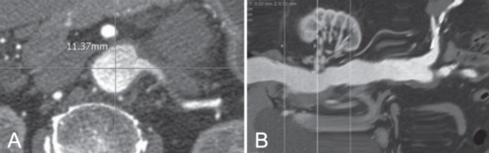
A Sample measurement of the transverse distance of the left renal artery on an axial image. The transverse distance was measured from the central grid line directly to the left renal artery. B Sample measurement of the vertical distance of the left renal artery from the celiac axis on a curved multiplanar reconstruction image
Fenestrated stent graft design
Trunk-type fenestrated stent grafts were designed according to the measurements and calculated distances. First, a fenestrated hall was made for the celiac axis 2.5 cm from the margin. From this first hall, the other three fenestrations were made based on the measured and calculated distances. On a paper template, vertical and transverse lines were drawn at the margin of the first fenestrated hall. Three transverse lines were drawn from the line at the lower margin of the first fenestrated hall at the measured distances. This paper template was attached to a round jig with a diameter 120% larger than the measured aortic diameter. Three points were marked on the template from the line that was drawn at both lateral margins of the first fenestrated hall at the calculated distance using a divider. Three halls (for the SMA, RRA and LRA) were made at the lateral lower corner at which two vertical and transverse lines intersected. Fenestrated halls were marked on Dacron fabric (S&G Biotech, Korea) and punched, and stents were sutured outside of this fabric (Figure 3).
Figure 3).

A The adjustments of measurements to the jig. B The formation of the hall for the branch vessels. C The completed fenestrated stent graft
The length of the proximal landing zone was 2.5 cm. When the trunk diameter was <26 mm in diameter, a 3 cm flared distal portion was produced to allow technical feasibility of branch placement. The stent graft diameter was 120% of the measured diameter at the proximal landing zone.
3-D model
DICOM data were converted to CAD data using the MIMICS program and the same parameters were measured. MIMICS is a modelling software that provides an interface between reconstructed tomographic angiography (TA), computed tomography (CT) or magnetic resonance image (MRI) slices and rapid prototyping machines by allowing the export of files in the stereolithography (STL) format, which is the industry standard for rapid prototyping using the STL+ model within MIMICS (32). The reconstruction process in MIMICS requires the selection of a proper threshold, which delineates all pixels in the entire data set within the specified range. This process assigns a certain colour to a region of interest (in this case, the diseased aorta).
The software refers to this combination of pixels as a mask and the 3-D model is generated based on this mask (Figure 4A) (33). After applying suitable thresholds, a region-growing function was used to retain all contiguous elements and a smoothing operation was performed on the 3-D object to obtain the final CAD model (Figure 3A). After exporting the STL files for the CAD models, the 3-D model of the aorta was produced using rapid prototyping technology incorporated with a fused deposition modelling (FDM) process. The FDM Maxum prototyping system (Stratasys Inc, USA) was used to process the FDM (Figure 3B). FDM Maxum has its own software (Insight, StratasysInc, USA) that can read only STL formatted files and automatically slices and generates necessary support structures as well as the material extrusion paths. On successful uploading of the STL files, FDM Maxum runs were performed to optimize the deposition sequencing of the model in the fabrication chamber. The process proceeds layer by layer, and creates an acrylonitrile-butadiene-styrene (ABS) resin model. Construction of the optimized FDM of the ABS aortic model took approximately 10 h to complete. Layers of ABS (178 μm thick) were deposited to produce the model (Figure 4B). This thickness represents the highest spatial resolution of the system (7).
Figure 4).

A Reconstructed three-dimensional model produced using the computer-assisted design program. B Actual printed three-dimensional model
Data analysis
Measurements were evaluated using Bland-Altman analysis (34) and concordance correlation coefficients (CCCs) (35). MedCalc statistical software version 10.0.0 (MedCalc Software, Belgium) was used to perform statistical analyses. The measurement error was calculated as the mean SD of the difference in measurement of the four measurements per target vessel (orientation and distance) and was averaged for all patients. The comparison with the measurements of the 3-D aorta model was expressed as the mean (± SD) difference in measurement and 95% CI. Orientation was represented by the transverse and vertical distances between a standard point (one point of the celiac orifice) and the other three branch vessels (SMA, RRA and LRA, respectively) in mm.
RESULTS
Image data acquisition
DICOM data sets of 10 patients were used in the present study. The quality of the CT images was considered to be satisfactory for postprocessing (MPR, cMPR and volume rendering) in all patients.
Stent design using reconstructed images
Four diameters, three vertical distances and three transverse distances were measured in 10 patients. Measurement data including SDs are summarized in Table 1. The diameters of the celiac axis, SMA, RRA and LRA were 6.70 mm, 8.43 mm, 5.92 mm and 6.31 mm, respectively.
TABLE 1.
Measurements of diameters and transverse and vertical distances (n=10)
| PACS | CAD | |
|---|---|---|
| CA | 6.70±1.39 | 6.39±1.34 |
| SMA | 8.43±1.84 | 7.93±1.29 |
| RRA | 5.29±2.19 | 5.78±1.87 |
| LRA | 6.31±2.21 | 5.40±1.69 |
| CA-SMA (T) | 4.02±3.41 | 2.87±2.56 |
| CA-RRA (T) | 8.59±4.74 | 8.21±4.77 |
| CA-LRA (T) | 15.62±4.57 | 14.64±4.73 |
| CA-SMA (V) | 18.59±9.07 | 18.46±8.57 |
| CA-RRA (V) | 32.23±18.23 | 33.9±21.83 |
| CA-LRA (V) | 33.58±16.46 | 33.48±16.30 |
Data presented as mean ± SD. CA Celiac axis; CAD Computer-assisted design; LRA Left renal artery; PACS Picture archiving and communication system; RRA Right renal artery; SMA Superior mesenteric artery; T Transverse; V Vertical
Fenestrated stent graft fabrication
Ten fenestrated stent grafts were fabricated based on the measurements. Four holes were made in the fabric and the fenestrated fabric was attached to the stent skeleton. The diameter of the manufactured stent graft was 24 mm in two grafts, 26 mm in four grafts, 28 mm in two grafts and 30 mm in one graft. In six stent grafts (diameter 24 mm and 26 mm) the distal 3 cm segment was flared to 4 mm.
3-D model
Ten sets of DICOM CTA data were successfully converted to CAD data and processed to produce 3-D models. All distances were measured using the MIMICS program. Measurement data, including SDs, are shown in Table 1. The diameters of the celiac axis, SMA, RRA and LRA were 6.39 mm, 7.93 mm, 5.78 mm and 5.40 mm, respectively.
Data analysis
In Bland-Altman plots of variability (95% limits of agreement) of the two data sets, the bias was −0.1927 mm and the 95% limits of agreement were −3.9344 mm and 3.5490 mm for absolute difference (measurements in PACS versus 3-D aorta model).
The CCC for variability was 0.9974 (95% CI 0.9904 to 0.9993). The bias in transverse and vertical distances between the standard point and branch vessel was −0.06455 mm and the 95% limits of agreement were −1.1418 mm and 1.0127 mm for the absolute difference (measurements in PACS versus 3-D aorta model). The CCC for variability was 0.9999 (95% CI 0.9997 to 1.0000). Gross comparison and direct measurements between the fabricated stent grafts and the printed 3-D models were well matched.
DISCUSSION
Since Anderson et al (36) first described EVAR for pararenal and suprarenal aneurysm with fenestrated stent grafts in 1999, it has become a treatment option for complex aneurysms unsuitable for standard infrarenal placement of stent graft due to the lack of an adequate landing zone. However, the use of fenestrated stent grafts is technically demanding and time-consuming because measurements and design need to be performed using CTA data.
Accuracy is essential in the design and manufacturing of fenestrated stent grafts. The use of 3-D work stations have facilitated this task; however, concerns regarding intra- and interobserver variability persist. Recently, this has been demonstrated to be a significant problem in a small percentage of patients. Standardization of the terminology relating to juxtarenal aneurysm is currently lacking and may improve the communication of results and act as a guide in treatment. In our study, 10 patients with unsuitable anatomy were enrolled, and fenestrated stent grafts were fabricated based on the measurements. MPR and cMPR images can now be processed in workstations without difficulty. This novel measurement technique uses MPR and cMPR images, which are familiar to operators, and minimizes interobserver variability. Our results showed that the two data sets were identical, with a CCC of 0.999.
To improve the versatility of fenestrated stent grafts, the measurement technique needs to be simple, standardized and have low interobserver variability. This new measurement technique uses vertical and transverse distances to minimize interobserver measurement error. Transverse distance can be measured from the vertical centre line to the nearest outer wall of each branch vessel. The actual distance from the celiac axis to each branch vessel was calculated using the distance from the central line. For example, the distance of the RRA can be calculated using the following equation:
The concept of central repositories of ready-made, off-the-shelf fenestrated stent graft designs is gaining interest and appears to be a potentially realistic prospect in the near future (37). This may make fenestrated stent graft technology available to more patients, particularly those with emergency presentation, and would also reduce cost. With solutions to increase applicability on the horizon, it would appear logical for appropriately trained endovascular specialists in regional centres to be able to size and design fenestrated stent grafts (38). This would not only decrease the time to fabrication, but would also allow for proper fenestrated stent grafts to be chosen ‘off the shelf’ in the emergency setting and for those who are at risk of rupture and cannot wait the current six to eight weeks required for customization. A direct measurement technique using standard points was simple to perform and was also easily applied to fabrication. We believe the preparation time will be shortened with this method. Once patients’ measurements are collected and analyzed, standardization of fenestrated stent graft may be possible and the versatility of stent graft devices will be improved.
CONCLUSION
A new measurement technique for the design of fenestrated stent grafts to treat complex abdominal aortic aneurysms was simple to perform and showed high accuracy compared with a 3-D aorta model produced using the CAD technique. Clinical application of this fenestrated design for evaluating technical feasibility is warranted.
Footnotes
FUNDING: Supported by grant number 02-2007-027 from the Seoul National University Bundang Hospital research fund.
REFERENCES
- 1.Parodi JC. Endoluminal treatment of arterial diseases using a stent-graft combination: Reflections 20 years after the initial concept. J Endovasc Surg. 1997;4:3–4. doi: 10.1583/1074-6218(1997)004<0003:ETOADU>2.0.CO;2. [DOI] [PubMed] [Google Scholar]
- 2.Volodos SM, Sayers RD, Gostelow JP, Bell P. Factors affecting the displacement force exerted on a stent graft after AAA repair – an in vitro study. Eur J Vasc Endovasc Surg. 2003;26:596–601. doi: 10.1016/j.ejvs.2003.08.002. [DOI] [PubMed] [Google Scholar]
- 3.Sun Z. Endovascular stent graft repair of abdominal aortic aneurysms: Current status and future directions. World J Radiol. 2009;1:63–71. doi: 10.4329/wjr.v1.i1.63. [DOI] [PMC free article] [PubMed] [Google Scholar]
- 4.Bortone AS, De Cillis E, D’Agostino D, Schinosa Lde L. Stent graft treatment of thoracic aortic disease. Surg Technol Int. 2004;12:189–93. [PubMed] [Google Scholar]
- 5.Ishimaru S. [Endovascular stent-graft repair for thoracic aortic aneurysm] Kyobu Geka. 2006;59(8 Suppl):666–73. [PubMed] [Google Scholar]
- 6.Saratzis N, Antonitsis P, Melas N, et al. Midterm results of endovascular abdominal aortic aneurysm repair with Talent stent graft in a single center. Int Angiol. 2006;25:197–203. [PubMed] [Google Scholar]
- 7.Nevala T, Perala J, Aho P, et al. Outcome of symptomatic, unruptured abdominal aortic aneurysms after endovascular repair with the Zenith stent-graft system. Scand Cardiovasc J. 2008;42:178–81. doi: 10.1080/14017430701819105. [DOI] [PubMed] [Google Scholar]
- 8.Pol RA, Zeebregts CJ, van Sterkenburg SM, Reijnen MM. Thirty-day outcome and quality of life after endovascular abdominal aortic aneurysm repair in octogenarians based on the Endurant Stent Graft Natural Selection Global Postmarket Registry (ENGAGE) J Vasc Surg. 2012;56:27–35. doi: 10.1016/j.jvs.2011.12.080. [DOI] [PubMed] [Google Scholar]
- 9.Criado FJ, Fry PD, Machan LS, Twena M, Patten P. The talent endoluminal AAA stent-graft system. Report of the phase I USA trial, and summary of worldwide experience. J Mal Vasc. 1998;23:371–3. [PubMed] [Google Scholar]
- 10.Rigberg DA, Dorafshar A, Sridhar A, Quinones-Baldrich W, Moore WS. Abdominal aortic aneursym: Stent graft vs clinical pathway for direct retroperitoneal repair. Arch Surg. 2004;139:941–4. doi: 10.1001/archsurg.139.9.941. discussion 945–6. [DOI] [PubMed] [Google Scholar]
- 11.Avgerinos ED, Dalainas I, Kakisis J, Moulakakis K, Giannakopoulos T, Liapis CD. Endograft accommodation on the aortic bifurcation: An overview of anatomical fixation and implications for long-term stent-graft stability. J Endovasc Ther. 2011;18:462–70. doi: 10.1583/11-3411.1. [DOI] [PubMed] [Google Scholar]
- 12.Qu L, Raithel D. From clinical trials to clinical practice: 612 cases treated with the Powerlink stent-graft for endovascular repair of AAA. J Cardiovasc Surg (Torino) 2009;50:131–7. [PubMed] [Google Scholar]
- 13.Guidoin R, Peirano MA, Barone HD, et al. Transrenal deployment of a modular stent graft to repair AAAs with short necks: Experiments in dogs. Artif Cells Blood Substit Immobil Biotechnol. 2008;36:310–39. doi: 10.1080/10731190802239016. [DOI] [PubMed] [Google Scholar]
- 14.Sampaio SM, Panneton JM, Brink JS, Andrews JC, McKusick MC, Gloviczki P. Aorto uni-iliac modification of a bifurcated stent graft for endovascular aneurysm repair: Expanding the versatility of a modular device. Vasc Endovascular Surg. 2006;40:103–7. doi: 10.1177/153857440604000203. [DOI] [PubMed] [Google Scholar]
- 15.Criado FJ, Fairman RM, Becker GJ. Talent LPS AAA stent graft: Results of a pivotal clinical trial. J Vasc Surg. 2003;37:709–15. doi: 10.1067/mva.2003.230. [DOI] [PubMed] [Google Scholar]
- 16.Greenberg RK, Turc A, Haulon S, et al. Stent-graft migration: A reappraisal of analysis methods and proposed revised definition. J Endovasc Ther. 2004;11:353–63. doi: 10.1583/03-1142R.1. [DOI] [PubMed] [Google Scholar]
- 17.Malas MB, Ohki T, Veith FJ, et al. Absence of proximal neck dilatation and graft migration after endovascular aneurysm repair with balloon-expandable stent-based endografts. J Vasc Surg. 2005;42:639–44. doi: 10.1016/j.jvs.2005.06.017. [DOI] [PubMed] [Google Scholar]
- 18.Ghanim K, Mwipatayi BP, Abbas M, Sieunarine K. Late stent-graft migration secondary to separation of the uncovered segment from the main body of a Zenith endoluminal graft. J Endovasc Ther. 2006;13:346–9. doi: 10.1583/05-1724.1. [DOI] [PubMed] [Google Scholar]
- 19.Chan KK, Siu WT, Fung KH, Yau KK, Wong SK, Li MK. Acute symptomatic abdominal aortic aneurysm secondary to endovascular stent graft associated type II endoleak. Asian J Surg. 2006;29:157–60. doi: 10.1016/S1015-9584(09)60077-4. [DOI] [PubMed] [Google Scholar]
- 20.Kougias P, Lin PH, Dardik A, Lee WA, El Sayed HF, Zhou W. Successful treatment of endotension and aneurysm sac enlargement with endovascular stent graft reinforcement. J Vasc Surg. 2007;46:124–7. doi: 10.1016/j.jvs.2007.02.067. [DOI] [PubMed] [Google Scholar]
- 21.Van Herzeele I, Lefevre A, Van Maele G, Maleux G, Vermassen F, Nevelsteen A. Long-term surveillance is paramount after implantation of the Vanguard stent-graft for abdominal aortic aneurysms. J Cardiovasc Surg (Torino) 2008;49:59–66. [PubMed] [Google Scholar]
- 22.Kvinlaug KE, Lawlor DK, Forbes TL, et al. Early results from a Canadian multicenter prospective registry of the Endurant stent graft for endovascular treatment of abdominal aortic aneurysms. J Endovasc Ther. 2012;19:58–66. doi: 10.1583/11-3622.1. [DOI] [PubMed] [Google Scholar]
- 23.Makaroun MS, Tuchek M, Massop D, et al. One year outcomes of the United States regulatory trial of the Endurant stent graft system. J Vasc Surg. 2011;54:601–8. doi: 10.1016/j.jvs.2011.03.002. [DOI] [PubMed] [Google Scholar]
- 24.Verhoeven EL, Oikonomou K, Mohner B, Renner H, Ritter W. First experience with the new repositionable C3 excluder stent-graft. J Cardiovasc Surg (Torino) 2011;52:637–42. [PubMed] [Google Scholar]
- 25.van Keulen JW, de Vries JP, Dekker H, et al. One-year multicenter results of 100 abdominal aortic aneurysm patients treated with the Endurant stent graft. J Vasc Surg. 2011;54:609–15. doi: 10.1016/j.jvs.2011.02.053. [DOI] [PubMed] [Google Scholar]
- 26.Hyhlik-Durr A, Weber TF, Kotelis D, et al. The Endurant stent graft system: 15-month follow-up report in patients with challenging abdominal aortic anatomies. Langenbecks Arch Surg. 2011;396:801–10. doi: 10.1007/s00423-011-0806-7. [DOI] [PubMed] [Google Scholar]
- 27.Ziegler P, Perdikides TP, Avgerinos ED, Umscheid T, Stelter WJ. Fenestrated and branched grafts for para-anastomotic aortic aneurysm repair. J Endovasc Ther. 2007;14:513–9. doi: 10.1177/152660280701400412. [DOI] [PubMed] [Google Scholar]
- 28.Verhoeven EL, Tielliu IF, Bos WT, Zeebregts CJ. Present and future of branched stent grafts in thoraco-abdominal aortic aneurysm repair: A single-centre experience. Eur J Vasc Endovasc Surg. 2009;38:155–61. doi: 10.1016/j.ejvs.2009.05.002. [DOI] [PubMed] [Google Scholar]
- 29.Mastracci TM. Fenestrated endografts for complex abdominal aortic aneurysms. Perspect Vasc Surg Endovasc Ther. 2010;22:214–8. doi: 10.1177/1531003511401423. [DOI] [PubMed] [Google Scholar]
- 30.Adam DJ, Verhoeven EL. Development of off-the-shelf stent grafts for juxtarenal abdominal aortic aneurysms. Eur J Vasc Endovasc Surg. 2012;43:661. doi: 10.1016/j.ejvs.2012.03.012. [DOI] [PubMed] [Google Scholar]
- 31.Bungay PM, Burfitt N, Sritharan K, et al. Initial experience with a new fenestrated stent graft. J Vasc Surg. 2011;54:1832–8. doi: 10.1016/j.jvs.2011.05.115. [DOI] [PubMed] [Google Scholar]
- 32.Seong J, Sadasivan C, Onizuka M, et al. Morphology of elastase-induced cerebral aneurysm model in rabbit and rapid prototyping of elastomeric transparent replicas. Biorheology. 2005;42:345361. [PubMed] [Google Scholar]
- 33.Doyle BJ, Morris LG, Callanan A, Kelly P, Vorp DA, McGloughlin TM. 3D reconstruction and manufacture of real abdominal aortic aneurysms: From CT scan to silicone model. J Biomech Eng. 2008;130:034501. doi: 10.1115/1.2907765. [DOI] [PubMed] [Google Scholar]
- 34.Bland JM, Altman DG. Comparing methods of measurement: Why plotting difference against standard method is misleading. Lancet. 1995;346:1085–87. doi: 10.1016/s0140-6736(95)91748-9. [DOI] [PubMed] [Google Scholar]
- 35.Lin LI. A concordance correlation coefficient to evaluate reproducibility. Biometrics. 1989;45:255–68. [PubMed] [Google Scholar]
- 36.Anderson JL, Berce M, Hartley DE. Endoluminal aortic grafting with renal and superior mesenteric artery incorporation by graft fenestration. J Endovasc Ther. 2001;8:3–15. doi: 10.1177/152660280100800102. [DOI] [PubMed] [Google Scholar]
- 37.Nordon IM, Hinchliffe RJ, Manning B, et al. Toward an “off-the-shelf” fenestrated endograft for management of short-necked abdominal aortic aneurysms: An analysis of current graft morphological diversity. J Endovasc Ther. 2010;17:78–85. doi: 10.1583/09-2895R.1. [DOI] [PubMed] [Google Scholar]
- 38.Manning BJ, Hinchliffe RJ, Ivancev K, Harris PL. Ready-to-fenestrate stent grafts in the treatment of juxtarenal aortic aneurysms: Proposal for an off-the-shelf device. Eur J Vasc Endovasc Surg. 2010;39:431–5. doi: 10.1016/j.ejvs.2010.01.012. [DOI] [PubMed] [Google Scholar]