

Abstract
Though it is widely accepted that fiber alignment has a great influence on the mechanical anisotropy of tissues, a systematic study of the influence of fiber alignment on the macroscopic mechanical behavior by native tissues is precluded due to their predefined microstructure and heterogeneity. Such a study is possible using collagen-based bioartificial tissues that allow for alignment to be prescribed during their fabrication. To generate a systemic variation of strength of fiber alignment, we made cruciform tissue constructs in Teflon molds that had arms of different aspect ratios. We implemented our anisotropic biphasic theory of tissue-equivalent mechanics to simulate the compaction by finite element analysis. Prior to tensile testing, the construct geometry was standardized by cutting test samples with a 1:1 cruciform punch after releasing constructs from the molds. Planar biaxial testing was performed on these samples, after stretching them to their in-mold dimensions to recover in-mold alignment, to observe the macroscopic mechanical response with simultaneous fiber alignment imaging using a polarimetry system. We found that the strength of fiber alignment of the samples prior to release from the molds linearly increased with anisotropy of the mold, and the modulus ratio (modulus in fiber-direction) / (modulus in normal-direction) was greater as the initial strength of fiber alignment increased, that is, as the aspect ratio increased. We also found that the fiber alignment strength and modulus ratio increased in a hyperbolic fashion with stretching for a sample of given aspect ratio.
Keywords: bioartificial tissue, tissue tensile mechanical properties, collagen fiber alignment, planar biaxial testing, polarimetry, tissue modulus, tissue mechanical anisotropy
INTRODUCTION
Most native and bioartificial soft tissues possess a complex microstructure that is anisotropic and heterogeneous, in accordance with function, and differs from tissue to tissue [1, 2]. Furthermore, tissue damage or disease can result in altered structure, such as compromised fiber alignment, that is adverse to proper function on both the microscopic and macroscopic scales [3–6]. It is widely accepted that fiber alignment has a great influence on the mechanical anisotropy of tissues as demonstrated in structure-based mechanical studies [7, 8]. Nonetheless, a systematic study of the influence of fiber alignment on the macroscopic mechanical behavior using native tissues has been precluded due to their predefined network fiber alignment and often complicated by spatial heterogeneity in composition and microstructure, such as occurs in multi-layered tissues (e.g. heart valve leaflets, arteries, cartilage). This difficulty has motivated the use of collagen-based bioartificial tissues to probe biaxial mechanical properties [9–12]. Systematic variation of initial fiber alignment was not possible with the methods used in these studies.
The primary goal of this study was to investigate the effect of fiber alignment on the macroscopic planar biaxial mechanical properties of a bioartificial tissue possessing, as well as to describe a method to fabricate a cruciform bioartificial tissue with initial fiber alignment that can be systematically varied. In the present study, we used collagen-based bioartificial tissues that were relatively homogeneous and fabricated with varied strength of fiber alignment. Their alignment was generated by the cruciform mold geometry in which they were formed and by the mechanical constraints imposed during cell induced collagen gel compaction, a fabrication strategy that has previously been implemented to generate tissue constructs with prescribed alignment patterns in different geometries [13, 14]. We implemented the anisotropic biphasic theory (ABT) of tissue-equivalent mechanics that accounts for fiber alignment (and resultant cell alignment) arising from anisotropic network strain generated during mechanically-constrained cell induced gel compaction [15] to simulate the compaction by finite element analysis [16]. The fiber alignment was quantified using a polarimetry system that generates an alignment image (direction and strength of fiber alignment at each pixel) of collagenous (birefringent) tissues during mechanical testing [17–19]. Quasi-static planar equibiaxial testing was performed to examine the correlation of biaxial tensile properties with fiber re-orientation from the initial alignment state.
MATERIALS AND METHODS
Cruciform Teflon Mold
Three identical sets of cruciform Teflon molds that had arms of different aspect ratios (AR = Wf:Wn = 1:1, 1:0.75, 1:0.5, 1:0.375, and 1:0.25, where subscripts f and n denote the fiber and normal directions, respectively) were made to fabricate collagen-based cruciform tissue constructs. The arm width Wf was fixed as 8 mm, and the arm width Wn varied as 8 mm, 6 mm, 4 mm, 3 mm and 2 mm. The arm lengths for all of the molds were 16 mm. The thickness of the molds was 5 mm. To avoid the tearing of the gel at mold corners (between arms) during the cell-driven gel compaction, a 3 mm radius of curvature was machined at the corners. To impose the desired mechanical constraints to gel compaction, small pieces of Velcro were glued with Super Glue (Henkel Consumer Adhesive, Inc) to the ends of each arm. The molds were sterilized by washing with antibacterial soap and then autoclaving for 30 minutes at 120 °C.
Fabrication of Cruciform Tissue Constructs
Collagen gel-forming solution seeded with neonatal human dermal fibroblasts was prepared as previously described [13]. The initial collagen and cell concentrations were 2.2 mg/ml and 0.5 million/ml, respectively. Vacuum grease (Dow Corning, Midland, MI) was applied to the bottom of the molds to prevent leakage. After each mold had been placed into one well of a 6-well plate (Corning Incorporated, Corning, NY), the cell suspension was pipetted into the molds. The plates were incubated at 37°C until gelation occurred (approximately 30 min). 5 ml of complete medium per well (low glucose DMEM (Mediatech, Inc, Herndon, VA) + 10% Fetal Bovine Serum (SH30071.03, HyClone, Logan, Utah), 1% penicillin-streptomycin, 1% fungizone, 1% l-glutamine) was added to each well and changed twice weekly.
Test Sample Preparation and Characterization
Constructs were incubated for two weeks. Just prior to their release from the molds, which was achieved by making a cut at the Velcro with a surgical blade (Swann-Motorn, Inc), images of the direction and strength of fiber alignment were derived from the slow axis direction and retardation, respectively, at each pixel using our previously described polarimetric imaging method [17]. We normalized the retardation by the average thickness of the tissue to calculate birefringence (Δn) image. We assume retardation and Δn to be indicative of the strength of fiber alignment [19, 20].
When the constructs were released from the molds, significant retraction occurred due to residual stress. To calculate the amount of retraction, 4 dots defining a square (3–4 mm × 3–4 mm) in the central area and 4 dots on the four arms (near the Velcro) of the sample were marked using Voerhoff’s stain. Local and global retractions were defined by the 4 dots at the central area and the 4 dots at the arms, respectively, by linear shortening in the aligned-fiber and normal-fiber directions. Prior to biaxial testing, samples were stretched to recover their in-mold dimensions (i.e. prior to release) to define their zero-strain state reference configuration (Fig. 1).
Fig. 1.

Image of test sample, following punching to AR = 1:1 from a retracted cruciform construct, mounting for biaxial mechanical testing, and stretching back to in-mold dimensions. Custom adjustable compressive grips especially designed for small-dimension these tissue constructs were attached to the ends of each actuator. The four dots at the center of the specimen were made with Voerhoff’s stain after mounting and stretching to track the local strain. The four dots visible at the corners, which were in the central region prior to punching the AR = 1:1 test sample, were made prior to release from the mold and retraction to track local retraction. Another (third) set of dots no longer visible after punching the test sample from was marked near the Velcro at each arm prior release from the mold and used to measure global retraction.
While cruciform constructs having varied Wn possessed varying degrees of alignment, as desired, they also possessed arms with varying cross-sectional area. This made it difficult to define a stress in the biaxial testing that could be directly compared across samples with different Wn. Thus, test samples with uniform dimensions were obtained by utilizing a cruciform punch with aspect ratio AR = 1:1 to cut the samples from the cruciform constructs following their release from the molds, where Wf = 2.5 mm, the minimum value that allowed a sample to be handled and mounted. The arm length was 4.25 mm. A radius of curvature of 0.8 mm was machined at the corners to avoid tearing due to stress concentration during biaxial extension. Two sets of cruciform constructs (with two replicates for each Wf :Wn) were made for this study (i.e. n = 4 for each Wn). From the two sets of constructs, only AR = 1:1.0, 1:0.5 and 1:0.375 samples were further characterized as constructs with AR = 1:0.25 possessed an arm width smaller than 2.5 mm after the 2 wk compaction period. Alignment images of the test samples were taken prior to mounting for biaxial testing. Following mounting and stretching to recover the dimensions based on local retraction, a third set of 4 dots was placed at the center of the mounted test sample for strain measurements.
Finite Element Simulation & Anisotropic Biphasic Theory (ABT)
3D FEA using the ABT formulation described in Barocas and Tranquillo [15] was used to simulate cell induced gel compaction using the method recently described in Ohsumi et al. [16], with free surface conditions everywhere, except at the ends of the arms where no displacement was enforced. Simulations were made using the same model parameters as in Barocas et al. (1997). The eigenvectors and eigenvalues of the fiber alignment tensor, which is defined via the network strain tensor, were used to acquire fiber direction and alignment strength, respectively.
Planar Equibiaxial Mechanical Testing
Biaxial Testing System
The Instron-Sacks biaxial testing system was used to perform quasi-static planar equibiaxial mechanical tests. Each actuator had a capacity of 2000 N and 110 mm stroke (resolution: 0.05 μm, accuracy: ± 0.1 μm, max.ramp rate = 15.7 mm/sec). The load in the horizontal (in-plane) direction was measured by a dynamic load cell of ± 5 N capacity (resolution: ± 0.06 mN, accuracy: ± 0.5 % of reading from 1–100 % of full scale value). Two four-axis FastTrack 8800 digital controllers were used to control four actuators. They monitored the load and displacement while performing high-speed data acquisition. The FastTrack 8800 control console was connected to a personal computer running Windows NT. The RS Console software was used for interacting with FastTrack 8800 and generating the waveform. The axial forces and marker positions were continuously recorded at 100 Hz with Instron-Sacks video extensometer (marker tracking software, Instron, Inc). The testing bed placed on the auto-balancing pressure dampers greatly reduced the experimental noise.
Testing Protocol
Four custom adjustable compressive grips especially designed for small-dimension cruciform constructs were attached to each shaft-end of the actuators. Compressive grips rather than hooks were used because the samples were weak relative to most native soft tissues. Small strips of sanding sheet (Norton Abrasives, Inc., Worcester, MA) were attached by double-sided tape (3M, Inc., St. Paul, MN) to the grips to promote gripping and a homogeneous distribution of compressive force. The specimens were mounted in the grips with the fiber and normal directions aligned with the actuator axes (See Fig. 1). The thickness of the specimens was measured by using a custom linear variable displacement transducers that allowed for minimally invasive measurements and minimized artifacts.
We presumed the St.Venant effect was sufficiently dissipated by gripping the samples as far as possible from the central region where local strain was measured [8]. During testing, the position of the actuators along each axis was ramped slowly from a small pre-load (2 mN) to a designated peak value. Though planar biaxial experiments on native soft tissues have generally been run with either strain or load control [2, 21–23], displacement control was utilized for this study because simultaneous polarimetric imaging precluded strain control (see below). The testing was completed in an isotonic saline bath at room temperature. Specimens were pre-conditioned with five consecutive cycles, each with period 10 sec, yielding ramp rates of 0.21 – 0.28 mm/sec in the fiber and normal directions, respectively. Ramp rates in this quasi-static range do not appear to affect the stress-strain behavior of the sample appreciably. During mechanical testing, a high-speed polarimetry system captured image sets needed to compute alignment images (as a function of stretch ratio) off-line as previously described [17].
Stress/Strain Fields
For planar equibiaxial mechanical testing, the deformation gradient tensor F̃ can be written in terms of stretch ratios λ as,
| (1) |
where
| (2) |
The Cauchy stress was calculated by using Eq. (3) where J = det(F̃ ) maps differential volumes of reference configuration into the current configuration, and P̃ is the first Piola-Kirchhoff stress tensor. The components of P̃ are current forces acting on reference areas. For isochoric deformation, J = 1.
| (3) |
Although enforcing incompressibility for the tissue constructs undergoing quasi-static deformation is ambiguous (i.e., there could be some volume change due to exudation of interstitial fluid), we set J = 1. Thus, we have
| (4) |
where ff and fn are current forces acting on reference cross-sectional areas of sample in the fiber direction and cross fiber (normal) direction, respectively (hlf and hln, h = thickness, lf, ln = width in the fiber and normal directions, respectively). For convenience, we subsequently refer to the fiber and normal directions with subscripts “f” and “n”, respectively. The strain was measured by using the Instron-Sacks video extensometer (Instron, Inc., Canton, MA), which is a marker tracking system to measure the finite strains during soft tissue testing. Polarimetric imaging precluded the use of strain control because the periodic low light intensity inherent to the polarimetric method interfered with the tracking software as markers were “lost,” so local strains in response to equibiaxial actuator displacement were not generally equibiaxial. In order to present data as a function of equibiaxial strain (i.e. λ), the stress associated with the target λ in one direction had to be paired with the stress associated with an offset λ in the other direction, obtained for the same sample for a slightly different deformation associated with an incremental equibiaxial actuator displacement. These “offsets” were used to define the error bars for λ on the plots and were included in ANOVA (see below). Each sample was tested twice in succession with the identical equibiaxial displacement testing protocol; one was to acquire polarimetric images and the other was to acquire mechanical data. Given this procedure, the error bar for Δn at a given λ in Fig. 4 is the maximum of the error bars for tf and tn at that λ Though extreme care was provided to synchronize the timing and kinematics of the two successive tests, this might have contributed error in relating birefringence to stress and modulus via λ.
Fig. 4.

Stress vs. stretch ratio plots show stiffening and increasing mechanical anisotropy with stretching for AR > 1.
Modulus ratio
To correlate the stress/strain relations with microfibrillar structural variation, we defined modulus ratio (MR) as,
| (5) |
where Ef (= dtf /dλf) and En (= dtn / dλn) are the tangent moduli in the fiber direction and normal directions, respectively, at a particular λ. Ef and En were obtained from derivatives of 3rd-degree polynomial equations used to fit the stress-strain curves for each sample. There would be no preferred fiber direction for AR = 1:1 in theory, but there was some anisotropy in practice, allowing MR to be calculated in this case as well.
Statistical Analyses
All values reported in the table and plotted in the figures are expressed as mean ± standard deviation. The statistical significance of differences in MR and Δn with incremental values of λ was investigated using the F-test. Differences in the sensitivity coefficient derived from MR and Δn were assessed with the t-test. Significance level was set as P < 0.05.
RESULTS
In-mold Alignment of Cruciform Constructs
Representative compacted constructs in the cruciform Teflon molds are shown in Fig. 2(a). The widths of the thinner arms of the constructs following two weeks of cell induced gel compaction in the molds clearly varies with AR. Gaps between the construct and Teflon sides are evident, which became filled with culture medium, as are the attachments of the four arms to the Velcro strips. The corresponding polarimetric alignment maps of the constructs are shown in Fig. 2 (b), where the orientation and length of each segment indicating the local average (over 10 x 10 pixels) direction and strength of fiber alignment, respectively. (The polarimetric method yields, at each pixel, the extinction angle and retardation, which is used here synonymously with fiber direction and alignment strength.) The gray level is mapped to the alignment strength at each pixel. The maps indicate the collagen fibrils became predominantly aligned in the wider arm (Wf) direction and increased in alignment as the dimension of the thinner arm (Wn) decreased (i.e. as AR increased). The average retardation over the central region of the cruciform construct divided by its average thickness (i.e. <Δn>) increased linearly with the mold aspect ratio, i.e., with 1/Wn, as seen in Fig. 2(a).
Fig. 2.

Cruciform-shaped Teflon molds with bioartificial tissue constructs possess alignment that varies with arm dimensions. AR = 1:1 (a1, b1), 1:0.75 (a2, b2) 1:0.5 (a3, b3), 1:0.375 (a4, b4), and 1:0.25 (a5, b5). (a) photographs; (b) alignment maps, where each segment indicates the local-average direction and strength of fiber alignment and the gray level is mapped to the local alignment strength (i.e. pixel-wise retardation), with white being maximum and black minimum alignment. Stronger alignment in the direction of the wider arm is evident as the other arm becomes thinner. ABT-based FEM simulation of compaction and alignment of cruciform tissue constructs predicts observed dependence on cruciform mold arm dimensions. The fiber direction and strength of fiber alignment are represented by eigenvectors and magnitude of eigenvalues, respectively, of the fiber orientation tensor in (c1–c5).
Our 3D FEM simulations of cell induced gel compaction based on the ABT also predicted similar dependence of compaction-induced alignment on Wn. Principal directions and strengths of fiber alignment were represented by eigenvectors and eigenvalues of the fiber orientation tensor, respectively, as segments and a color map in Fig. 2(c). The experimental retardation images shown as the gray scale images shown in Fig. 2(b) and the simulated images shown as the color maps in Fig. 2(c) compare well. The predicted alignment strength averaged over the central region of the cruciform increased linearly with mold aspect ratio (Fig. 3(b)), as observed experimentally (Fig. 3(a)).
Fig. 3.

(a) The strength of fiber alignment linearly increased with mold aspect ratio (i.e. with 1/Wn). The average value of the birefringence <Δn> within the central region prior to sample release is plotted. (b) ABT-based FEM simulation of compaction and alignment of cruciform-shaped tissue constructs predicts the observed dependence of strength of fiber alignment linearly increasing with mold aspect ratio (1/Wn). The average value of the principal eigenvalue within the central region is plotted.
Retraction of Cruciform Constructs Upon Release From Molds
As shown in Table 1, the amount of global retraction was similar for all groups (AR = 1:1, 1:0.5, 1:0.375) in both the fiber and normal directions. Due to apparent heterogeneous distribution of “residual stress” (associated with the contracted collagen and/or sustained cell traction forces) within the constructs, the amount of global retraction and local retraction differed, with global retraction being greater than local retraction for all samples. Table 2 summarizes the residual stress associated with the contracted collagen and/or sustained cell traction forces. The local retraction in the fiber direction was similar in all groups. However, retraction in the normal direction was smaller for the groups AR = 1:0.50 and 1:0.375. Table 1 also shows the average dimensions and <Δn> in the central region of the representative cruciform constructs in-mold, after release, and upon stretching to in-mold dimensions, quantifying the loss and recovery of alignment, demonstrating that the in-mold alignment pattern was largely recovered.
Table 1.
The average dimensions and <Δn> in the central region of the representative cruciform constructs in-mold, after release, and upon stretching to in-mold dimensions, quantifying the loss and recovery of alignment. The amount of global and local retractions in the fiber- and normal directions are shown (* P < 0.05).
| AR | 1:1 | 1:0.5 | 1:0.37 | |
|---|---|---|---|---|
| Thickness after release from mold [mm] | 0.57 ± 0.02 | 0.73 ±0.01 | 0.70 ±0.12 | |
| Width in fiber direction [mm] | 2.14 ±0.11 | 2.05 ±0.14 | 2.27 ±0.01 | |
| Width in normal direction [mm] | 2.27 ±0.10 | 2.51 ±0.08 | 2.71 ±0.01 | |
| <Δn> in-mold [°/mm] | 7.86 ±1.87 * | 23.76 ±2.17 * | 32.47 ±3.43 * | |
| <Δn> after release from mold [°/mm] | 7.08 ±1.18 * | 14.48 ±1.27 * | 27.10 ±1.84 * | |
| <Δn> upon stretching to in-mold dimensions [°/mm] | 7.96 ±1.23 * | 22.88 ±1.50 * | 34.87 ±1.78 * | |
| Global retraction [%] | fiber | 33.98 ± 3.20 * | 33.23 ± 2.10 * | 34.79 ± 1.65 * |
| normal | 31.03 ± 5.91 * | 33.61 ± 0.01 * | 36.50 ± 0.87 * | |
| Local retraction [%] | fiber | 26.13 ± 2.10 * | 28.83 ± 1.92 * | 29.93 ± 1.99 * |
| normal | 23.53 ± 4.50 * | 19.62 ± 0.83 * | 20.79 ± 0.99 * | |
Table 2.
Residual stress associated with the contracted collagen and/or sustained cell traction forces.
| AR | Sf [kPa] | Sn [kPa] |
|---|---|---|
| 1:1 | 152.08 ± 5.03 | 150.72 ± 4.99 |
| 1:0.5 | 197.35 ± 1.91 | 66.65 ± 0.64 |
| 1:0.37 | 205.16 ± 35.92 | 69.07 ± 12.09 |
Correlation of Stress, Modulus, and Alignment Strength with Stretch Ratio in Test Samples
Fig. 4 shows the stress vs. stretch ratio curves for both the fiber-aligned (tff vs. λf) and normal (tnn vs. λn) directions during equibiaxial stretching and the associated <Δn> (alignment strength). Mechanical anisotropy was essentially absent for AR = 1:1 and became more evident as AR increased, as expected, since increased AR correlates with increasing initial alignment strength. The birefringence for AR = 1:1 was relatively small and constant over all values of λ, consistent with the samples’ grossly isotropic microstructure. The greatest AR = 1:0.375 showed, as expected, the strongest alignment for all values of λ, as well as the greatest difference in the tangent moduli En and Ef. The increase in alignment strength with λ for the cases AR =1:0.5 and 1:0.375 plateaued with increased λ.
Ef and En are plotted versus λ in Fig. 5. Interestingly, while the data exhibited the expected behavior at the smallest λ in that Ef was greater for the cases AR =1:0.5 and 1:0.375 as compared to AR = 1:1, there were unexpected trends. Ef was greater for AR = 1:0.5 vs. 1:0.375 at all λ, and Ef for AR = 1:1 became larger than Ef for both AR =1:0.5 and 1:0.375 at higher λ.
Fig. 5.
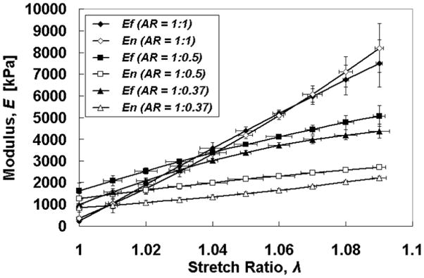
Modulus vs. stretch ratio plots show stiffening in both axes for all AR, but with unexpected trends (see text).
Modulus Ratio Correlation With Alignment Strength in Test Samples
MR and Δn increased in a hyperbolic fashion with stretching for AR = 1:0.5 and 1:0.375 until λ~ 1.05, after which there were no statistically significant changes (Fig. 6). Interestingly, the sensitivity of mechanical anisotropy to microstructural anisotropy (i.e. to fiber alignment) was greater for AR =1:0.375 as compared to AR = 1:0.5, as seen from the plot of (dMR/MR)/(dΔn/Δn) = dlnMR /dlnΔn = S vs. λ in Fig. 7, as well as being a high sensitivity (i.e. S ≫ 1).
Fig. 6.

Modulus ratio vs. stretch ratio plots show increasing mechanical anisotropy and alignment with higher aspect ratio. The fiber alignment strength (average birefringence) also exhibits hyperbolic increase with stretch ratio in the cases AR > 1.
Fig. 7.

Dependence of sensitivity of mechanical anisotropy relative to microstructural anisotropy on stretch ratio, showing the sensitivity is greater for the more aligned sample (AR = 1:0.375) and also decreases with stretch ratio. Values were derived from derivatives of cubic polynomial fits to the data in Fig. 6. Differences between AR = 1:0.5 and 1:0.375 are statistically significant for λ = 1.00 – 1.03.
Dynamic Imaging of Fiber Re-orientation in Test Samples
Polarimetric imaging during quasi-static cyclic planar equibiaxial stretching revealed a complicated relationship between λf, λn, and Δn for the cases AR = 1:0.5 and 1:0.375 (Fig. 8). Although the actuator motion was triangular, there was a non-triangular nature to the Δn traces, notably in the unstretching phase. This is not observed during uniaxial stretching of these constructs (not shown). Differences in the time points of the extrema are an artifact of data synchronization. Notice that while the traces for λf and λn diverge considerably at maximum stretching, they are nearly coincident (i.e. equibiaxial) at minimal stretching, in the range analyzed for MR. As expected, the case of AR = 1:1 exhibited no change in Δn with cyclic stretching and almost coincident traces of λf and λn, consistent with an isotropic microstructure.
Fig. 8.


Stretch ratios and fibril alignment strength possess a complex relationship in the cases AR > 1, particularly in the unstretching phase. (a) AR = 1:1, (b) AR = 1:0.5, and (c) AR = 1:0.375.
DISCUSSION
Collagen-based tissue constructs were formed in cruciform molds with varied arm width ratio, defined by the aspect ratio (AR), to obtain samples that possessed different degrees of initial alignment strength. Test samples with AR = 1:1 cut from these varied AR cruciform constructs were then used to investigate the relationship between fiber re-orientation (changes in alignment strength) and anisotropic tensile stiffness during planar equibiaxial stretching.
Cells entrapped in reconstituted collagen gel as used here are known to compact the collagen network extensively but neither degrade it nor synthesize extracellular matrix (ECM) extensively [24, 25]. Thus, while some collagen remodeling occurred over the two-week incubation, the far majority of the ECM in the samples tested is assumed to be the reconstituted collagen. Since the ECM in this study could thus be considered to be a homogeneous material, comprised of birefringent collagen fibrils, the interpretation of the birefringence signal is less prone to ambiguity (as would be the case for a tissue with multiple birefringent fiber populations and/or fiber directions in adjacent layers of a laminate tissue not being co-aligned). Even for the simplest case of a single fiber population without complicating form birefringence (which occurs when the interstitial medium is not of matched refractive index, as in this study), there is no general theory to relate fiber orientation distribution to birefringence. Our experience, however, is that greater birefringence in collagen-based tissue constructs is always indicative of greater alignment strength (e.g. [26]). The ability to image fiber alignment during mechanical testing, even if semi-quantitatively, is a considerable advantage of polarimetry compared to traditional imaging techniques [19].
The strong agreement between the observed in-mold alignment pattern and that predicted by the 3D FEM based on our anisotropic biphasic theory of cell-matrix mechanical interactions [15] indicated that the theory was suitable for predicting the evolution of fiber alignment in the cruciform geometry (with mechanical constraints imposed at the ends of the arms) as has been the case in other geometries represented by arteries [14] and heart valves. The agreement included not only the global increase in alignment strength with increasing AR (i.e. proportional to 1/Wn), but the fine alignment pattern, including the occurrence of two relatively isotropic regions centered on the axis of the normal direction with increasing AR (cf. Fig. 3). Indeed, the increasing complexity of the alignment field with increasing AR for more rigorous testing of model validity can be considered another advantage of the cruciform geometry.
The residual stress developed during gel compaction in the cruciform constructs was an interesting result and could be used to validate models of mechanics of contractile tissues; however, the main point for this study and future studies that exploit the method described here is that the in-mold alignment field is distorted if the sample is released from the mold but can be largely recovered by stretching the sample back to its pre-release dimensions. Concerning the finding that the local retraction (i.e. in the central region of the cruciform) was greater in the fiber direction rather than the normal direction for the AR = 1:0.5 and 1:0.375 cases, it would be expected given the majority of cells in the central region are aligned in the fiber direction in those cases. The reason why the global retraction (i.e. spanning the arms) was the same in both directions is not clear, but it indicates that the retraction in the arms of the cruciform in the normal direction was significantly greater as compared to the fiber direction given that the converse was true in the central region. Future studies would benefit from devising a mold that allows the sample to be transferred and mounted on the biaxial testing system without release from the constraint at the end of each arm.
The basic planar biaxial testing results from this study are consistent with those reported by Thomopoulos et. al. [11] who studied similarly prepared tissue constructs. Using load control, they acquired the equibiaxial properties of square constructs that were mechanically constrained either along all four edges or just two opposing edges, yielding isotropic and aligned constructs, respectively, after 3 days of cell induced collagen gel compaction. Only the aligned constructs, essentially corresponding to one AR, exhibited mechanical anisotropy, consistent with our results in Fig. 4. We report data here for multiple AR and the evolution of alignment with stretching, but do not attempt to model the data as did Thomopoulos et. al.
The central regions of the AR = 1:0.5 and 1:0.375 test samples exhibited an increase in alignment strength with equibiaxial stretching (Fig. 4), although the increase diminished with increasing stretch ratio. Nonetheless, the increase in <Δn> up to λ = 1.05 was significant (p < 0.05), indicating a complex microstructural response since an increase in alignment strength is not predicted from an affine model of fiber reorientation. As expected, the modulus ratio (MR, defined as the ratio of tangent moduli in the fiber and normal directions, Ef and En) was greater in the test samples with higher AR, that is, with greater alignment strength (Fig. 6). While En increased approximately linearly with stretch ratio (Fig. 5), Ef increased hyperbolically, causing MR to plateau after an increase over stretch ratios up to λ = 1.05. These findings would be consistent with a re-orientation of fibrils away from the normal direction into the fiber direction over low stretch ratios during equibiaxial stretching. However, the reorientation response is different under equibiaxial stretching and unstretching as indicated by the birefringence traces in Fig. 8. Also, the mechanical anisotropy (MR) was more sensitive to changes in microstructural anisotropy (Δn) for the more aligned sample (AR = 1:0.375), as shown in Fig. 7. These complex responses will be useful for development and validation of multiscale microstructural models of tissue constructs, as recently undertaken [27]. The response for the AR = 1:1 case was consistent with that predicted for an isotropic microstructure: low birefringence independent of stretch ratio and comparable values of Ef and En at all stretch ratios, although there was a stiffening evident at all stretch ratios.
While the trends in MR are readily explicable, two trends observed for the individual tangent moduli were unexpected: Ef being greater for AR = 1:0.5 vs. 1:0.375 at all λ, and Ef for AR = 1:1 becoming larger than Ef for both AR =1:0.5 and 1:0.375 at higher λ. This suggests complex multiaxial mechanical coupling behavior, which has been modeled with strain energy approaches [22, 28]. Observing complex behavior in these collagen-based tissue constructs was unexpected because they do not possess a composition and microstructure that is like native tissues, which is better approximated in fibrin-based tissue constructs where ECM production by the entrapped cells is extensive (e.g. [29]). However, the observed biaxial coupling may arise from effects peculiar to the collagen-based tissue constructs (e.g. fibril aggregation and crosslinking post-gel compaction).
One major challenge for tissue engineering is to understand how the microstructure is related to the macroscopic mechanical behavior of tissue constructs and how the constructs can be manufactured to meet the mechanical requirements. This experimental model provides a means to systematically study that relationship and achieve that goal.
Acknowledgments
NIH EB005813 (V.H.B.) and the UMN IPRIME TSE program for funding, the UMN NSF MRSEC DMR-0212302 for utilizing the Instron system, and the UMN Supercomputing Institute for computing resources for the simulations.
References
- 1.Guilak F. Functional tissue engineering. Springer; New York: 2003. [Google Scholar]
- 2.Humphrey JD. Cardiovascular solid mechanics: cells, tissues, and organs. Springer; New York: 2002. [Google Scholar]
- 3.Grieve DJ, Byrne JA, Cave AC, Shah AM. Role of oxidative stress in cardiac remodelling after myocardial infarction. Heart, lung & circulation. 2004;13(2):132–138. doi: 10.1016/j.hlc.2004.02.008. [DOI] [PubMed] [Google Scholar]
- 4.Harris JL, Humphrey JD. Kinetics of thermal damage to a collagenous membrane under biaxial isotonic loading. IEEE transactions on biomedical engineering. 2004;51(2):371–379. doi: 10.1109/TBME.2003.820375. [DOI] [PubMed] [Google Scholar]
- 5.Harris JL, Wells PB, Humphrey JD. Altered mechanical behavior of epicardium due to isothermal heating under biaxial isotonic loads. Journal of biomechanical engineering. 2003;125(3):381–388. doi: 10.1115/1.1567754. [DOI] [PubMed] [Google Scholar]
- 6.Woo SL, Abramowitch SD, Kilger R, Liang R. Biomechanics of knee ligaments: injury, healing, and repair. Journal of biomechanics. 2006;39(1):1–20. doi: 10.1016/j.jbiomech.2004.10.025. [DOI] [PubMed] [Google Scholar]
- 7.Billiar KL, Sacks MS. Biaxial mechanical properties of the native and glutaraldehyde-treated aortic valve cusp: Part II--A structural constitutive model. Journal of biomechanical engineering. 2000;122(4):327–335. doi: 10.1115/1.1287158. [DOI] [PubMed] [Google Scholar]
- 8.Sun W, Abad A, Sacks MS. Simulated bioprosthetic heart valve deformation under quasi-static loading. Journal of biomechanical engineering. 2005;127(6):905–914. doi: 10.1115/1.2049337. [DOI] [PubMed] [Google Scholar]
- 9.Billiar KL, Throm AM, Frey MT. Biaxial failure properties of planar living tissue equivalents. Journal of biomedical materials research. 2005;73(2):182–191. doi: 10.1002/jbm.a.30282. [DOI] [PubMed] [Google Scholar]
- 10.Thomopoulos S, Fomovsky GM, Chandran PL, Holmes JW. Collagen fiber alignment does not explain mechanical anisotropy in fibroblast populated collagen gels. Journal of biomechanical engineering. 2007;129(5):642–650. doi: 10.1115/1.2768104. [DOI] [PubMed] [Google Scholar]
- 11.Thomopoulos S, Fomovsky GM, Holmes JW. The development of structural and mechanical anisotropy in fibroblast populated collagen gels. Journal of biomechanical engineering. 2005;127(5):742–750. doi: 10.1115/1.1992525. [DOI] [PubMed] [Google Scholar]
- 12.Wagenseil JE, Elson EL, Okamoto RJ. Cell orientation influences the biaxial mechanical properties of fibroblast populated collagen vessels. Annals of biomedical engineering. 2004;32(5):720–731. doi: 10.1023/b:abme.0000030237.20057.3e. [DOI] [PubMed] [Google Scholar]
- 13.Neidert MR, Tranquillo RT. Tissue-Engineered Valves with Commissural Alignment. Tissue Engineering. 2006;12:891–903. doi: 10.1089/ten.2006.12.891. [DOI] [PubMed] [Google Scholar]
- 14.Barocas VH, Girton TS, Tranquillo RT. Engineered alignment in media-equivalents: Magnetic prealignment and mandrel compaction. J Biomech Eng. 1998;120(5):660–666. doi: 10.1115/1.2834759. [DOI] [PubMed] [Google Scholar]
- 15.Barocas VH, Tranquillo RT. An anisotropic biphasic theory of tissue-equivalent mechanics: the interplay among cell traction, fibrillar network deformation, fibril alignment, and cell contact guidance. Journal of biomechanical engineering. 1997;119(2):137–145. doi: 10.1115/1.2796072. [DOI] [PubMed] [Google Scholar]
- 16.Ohsumi TK, Flaherty JE, Evans MC, Barocas VH. Three-dimensional simulation of anisotropic cell-driven collagen gel compaction. Biomechanics and modeling in mechanobiology. 2008;7(1):53–62. doi: 10.1007/s10237-007-0075-0. [DOI] [PubMed] [Google Scholar]
- 17.Tower TT, Neidert MR, Tranquillo RT. Fiber alignment imaging during mechanical testing of soft tissues. Annals of biomedical engineering. 2002;30(10):1221–1233. doi: 10.1114/1.1527047. [DOI] [PubMed] [Google Scholar]
- 18.Tower TT, Tranquillo RT. Alignment maps of tissues: II. Fast harmonic analysis for imaging. Biophysical journal. 2001;81(5):2964–2971. doi: 10.1016/S0006-3495(01)75936-X. [DOI] [PMC free article] [PubMed] [Google Scholar]
- 19.Tower TT, Tranquillo RT. Alignment maps of tissues: I. Microscopic elliptical polarimetry. Biophysical journal. 2001;81(5):2954–2963. doi: 10.1016/S0006-3495(01)75935-8. [DOI] [PMC free article] [PubMed] [Google Scholar]
- 20.Hecht E. Optics. Addison-Wesley; Reading, Mass: 2002. [Google Scholar]
- 21.Billiar KL, Sacks MS. Biaxial mechanical properties of the natural and glutaraldehyde treated aortic valve cusp--Part I: Experimental results. Journal of biomechanical engineering. 2000;122(1):23–30. doi: 10.1115/1.429624. [DOI] [PubMed] [Google Scholar]
- 22.Sacks MS, Sun W. Multiaxial mechanical behavior of biological materials. Annual review of biomedical engineering. 2003;5:251–284. doi: 10.1146/annurev.bioeng.5.011303.120714. [DOI] [PubMed] [Google Scholar]
- 23.Sun W, Sacks M, Fulchiero G, Lovekamp J, Vyavahare N, Scott M. Response of heterograft heart valve biomaterials to moderate cyclic loading. Journal of biomedical materials research. 2004;69(4):658–669. doi: 10.1002/jbm.a.30031. [DOI] [PubMed] [Google Scholar]
- 24.Thie M, Schlumberger W, Semich R, Rauterberg J, Robenek H. Aortic smooth muscle cells in collagen lattice culture: effects on ultrastructure, proliferation and collagen synthesis. Eur J Cell Biol. 1991;55(2):295–304. [PubMed] [Google Scholar]
- 25.Clark RA, Nielsen LD, Welch MP, McPherson JM. Collagen matrices attenuate the collagen-synthetic response of cultured fibroblasts to TGF-beta. J Cell Sci. 1995;108(Pt 3):1251–1261. doi: 10.1242/jcs.108.3.1251. [DOI] [PubMed] [Google Scholar]
- 26.Guido S, Tranquillo RT. A methodology for the systematic and quantitative study of cell contact guidance in oriented collagen gels: Correlation of fibroblast orientation and gel birefringence. J Cell Sci. 1993;105:317–331. doi: 10.1242/jcs.105.2.317. [DOI] [PubMed] [Google Scholar]
- 27.Sander EA, Stylianopoulos T, Tranquillo RT, Barocas VH. Image-based biomechanics of collagen-based tissue equivalents: multiscale models compared to quantitative polarized light microscopy. IEEE Engineering in Medicine and Biology. doi: 10.1109/MEMB.2009.932486. submitted. (accepted) [DOI] [PMC free article] [PubMed] [Google Scholar]
- 28.Holzapfel GA. Determination of material models for arterial walls from uniaxial extension tests and histological structure. Journal of theoretical biology. 2006;238(2):290–302. doi: 10.1016/j.jtbi.2005.05.006. [DOI] [PubMed] [Google Scholar]
- 29.Robinson PS, Johnson SL, Evans MC, Barocas VH, Tranquillo RT. Functional tissue-engineered valves from cell-remodeled fibrin with commissural alignment of cell-produced collagen. Tissue Eng Part A. 2008;14(1):83–95. doi: 10.1089/ten.a.2007.0148. [DOI] [PubMed] [Google Scholar]