

Abstract
Mechanosensing by flagella is thought to trigger bacterial swarmer-cell differentiation, an important step in pathogenesis. How flagellar motors sense mechanical stimuli is not known. To study this problem, we suddenly increased the viscous drag on motors by a large factor, from very low loads experienced by motors driving hooks or hooks with short filament stubs, to high loads, experienced by motors driving tethered cells or 1-μm latex beads. From the initial speed (after the load change), we inferred that motors running at very low loads are driven by one or at most two force-generating units. Following the load change, motors gradually adapted by increasing their speeds in a stepwise manner (over a period of a few minutes). Motors initially spun exclusively counterclockwise, but then increased the fraction of time that they spun clockwise over a time span similar to that observed for adaptation in speed. Single-motor total internal reflection fluorescence imaging of YFP–MotB (part of a stator force-generating unit) confirmed that the response to sudden increments in load occurred by the addition of new force-generating units. We estimate that 6–11 force-generating units drive motors at high loads. Wild-type motors and motors locked in the clockwise or counterclockwise state behaved in a similar manner, as did motors in cells deleted for the motor protein gene fliL or for genes in the chemotaxis signaling pathway. Thus, it appears that stators themselves act as dynamic mechanosensors. They change their structure in response to changes in external load. How such changes might impact cellular functions other than motility remains an interesting question.
Keywords: Escherichia coli, mechanical load, stator remodeling
Mechanical forces play an important role in triggering changes in gene expression and biochemical signaling in many biological systems (1, 2). Mechanical inhibition of the rotation of flagellar motors (due to higher viscosities or proximity to surfaces) is known to trigger swarmer-cell differentiation, a key step in pathogenesis in some bacterial species (3–5). Previous investigations have measured the long-term effects of mechanical stimuli on gene expression and bacterial swarming, e.g., by varying the mechanical properties of the growth medium (6). However, little is known about how the flagellar motor senses mechanical stimuli at the molecular level. Here, we apply direct mechanical stimuli and report short-time adaptation in motor response that has not been measured before. These results reveal details of the immediate response to mechanical signals in flagellar motors.
Escherichia coli swim by rotating helical filaments driven by motors embedded in the cell wall. The motors switch between clockwise (CW) and counterclockwise (CCW) directions of rotation to bias cell movements in response to chemical gradients. Motor outputs, such as speed and the probability of CW rotation (CW bias), can be experimentally measured and reveal the immediate effects of stimuli on protein interactions associated with the motor. The mechanisms of adaptation to chemical stimuli are varied (7–9) and involve resetting of the CW bias to prestimulus levels. This adaptation in CW bias, which is essential for chemotaxis, is influenced by variations in the levels of the signaling molecule, CheY-P. However, CheY-P levels remain unchanged when motor rotation is mechanically inhibited by cross-linking adjacent filaments with antifilament antibody (10). Here, we show that motors adapt to mechanical stimuli (to sudden changes in load) by changing both their speeds and their CW bias. This adaptation is intrinsic to the motor and occurs through a change in the number of force-generating units driving the motor.
At low Reynolds numbers, the torque generated by the flagellar motor is matched at all times by the external viscous load on the flagellum. When a spherical bead of radius a is attached to a truncated flagellum (stub), the torque (and the viscous load) is 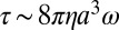 , where η is the viscosity of the external medium, and ω is the angular velocity of the motor (2πv, with v the speed in Hz). In previous measurements of steady-state torque–speed curves in flagellar motors, flagellar stubs were preloaded by attaching beads of different sizes, and each motor was perturbed by varying η (11). However, the changes in load were relatively small, and time was not allowed for detection of motor adaptation. In the present work, to avoid difficulties with viscous media (slow fluid transport and contaminants sensed as attractants or repellents), we held η constant and changed the size, a, of the object driven by the motor. This was done by using optical tweezers to place a 1-μm latex bead on a flagellar stub, or by allowing a cell (with a ∼2 μm) to self-tether via such a stub, as shown schematically in Fig. 1 A and B. After attachment, the bead and cell body represent large viscous loads, compared with the small viscous loads of freely rotating flagellar stubs before attachment. By these means, we were able to increase the viscous drag on the motor by a factor of several thousand in a few milliseconds. We measured the motor response immediately following the load change.
Fig. 1.

Adaptation to mechanical stimuli: (A) A cell is brought up to a 1-μm latex bead held in an optical trap (trap not shown). The bead binds to a short sticky-filament stub and its rotation is monitored. (B) A cell with a short sticky-filament stub is allowed to settle onto the surface of a glass cover-slip and self-tether. The rotation of the cell body is monitored. (C) Bead rotational speeds measured from the time of attachment, plotted as a function of time. Positive values are CCW; negative values are CW. The black line is the mean value of the absolute speed for the interval between successive steps. The arrow represents the time of mechanical stimulus. Dashed lines indicate speeds before increase in viscous loads. (D) Steady-state torque–speed curves for CCW rotation of the bacterial flagellar motor (solid curve). Two load lines are shown (dashed lines), one for high loads (Left, with a steep slope) and one for low loads (Right, with near-horizontal slope). The square near 300 Hz (state a) indicates the torque delivered by a single stator element to the motor at low loads. The filled circles (from state b to state c) represent the driving torques for the corresponding speeds at which the 1-μm bead rotates in Fig. 1C. The dotted lines indicate the driving torque on the motor for stator elements ranging in number from 1 to 11.
Results and Discussion
Adaptation in Motor Speed.
We optically trapped a 1-μm-diameter latex bead close to a cell stuck to the surface. Next, we translated the microscope stage until the bead tethered to a filament stub on the cell (Movie S1). At the instant of attachment, the load on the motor increased from a very low value (the viscous drag on a rotating stub) to a high value (the viscous drag on a rotating latex bead). Judging from earlier work, near zero load, a single stator element will rotate the motor at ∼300 Hz with switching rates ∼0.2 s−1 (12, 13). We measured the speed and direction of rotation of the bead as soon as possible (<5 s) following attachment to the motor. Upon the load increase, the motor speed dropped to ∼5–10 Hz as shown in Fig. 1C, lower than the expected steady speed (50–60 Hz) for a load of a 1-μm bead. Then, the speed increased in a stepwise fashion, approaching the expected steady speed. These step increments in speed are like those seen previously at fixed loads when stator elements of paralyzed mutants were replaced by wild-type elements through protein exchange (14, 15).
Fig. 1D shows the steady-state torque–speed relationship measured in previous studies for flagellar motors of E. coli, over a range of bead sizes and viscosities (13). The two load lines for our experiments are represented by the two dashed lines. One, with a near-horizontal slope, represents the low load for a short flagellar stub. The other, with a much steeper slope, represents the high load for a 1-μm bead. Before the bead was added, the operating point for the motor was at a steady-state a shown by the open square. When the bead was added, the operating point jumped to state b shown by the bottom closed circle, where the speed was relatively low. For the motor of Fig. 1C, the speed decreased from ∼300 Hz to 5–10 Hz and then increased in nine stepwise increments (6–11 for the set of seven motors studied) with the final operating point indicated at steady-state c, corresponding to a motor with n = 11 force-generating units. The experimental torque values indicated by the filled circles were calculated from the drag coefficient for a 1-μm bead and the motor speeds shown in Fig. 1C. These values match previously measured values for relative torques delivered by increasing numbers of stator elements, as indicated by the dotted lines (16).
Stator proteins have been visualized previously under constant loads by imaging GFP fusions of the stator protein MotB by total internal reflection fluorescence (TIRF) (17). To test whether the stator elements were added one after the other or were already present and were sequentially activated upon the change in load, we fused yellow fluorescent protein (eYFP) to MotB and observed the fusions under TIRF. We did this by adding sheared cells expressing YFP–MotB to a slide on a microscope also equipped for phase contrast. We waited for a cell to settle to the glass and tether on its own (Fig. 1B), which suddenly increased the load. The sudden change in speed (shown for wild-type cell in Movie S2) alleviated concerns about events that might have occurred during the lag between load change and speed measurement in the bead experiments. Once the cell tethered, we monitored motor fluorescence with TIRF (at visible wavelengths) and measured the rotation speed with phase contrast (in the infrared). The load for a tethered cell is larger than that for a 1-μm-diameter spherical bead, so the speed increments and final speeds were lower than shown in Fig. 1C; however, the same kind of stepwise increments in speed were observed. The motor in Fig. 2A showed at least two step increments in speed and reached a steady-state speed of ∼3.2 Hz. The corresponding TIRF images indicating the YFP–MotB assembly are shown in Fig. 2B. If the brightness of the fluorescent stator assembly increased with speed, it was considered evidence of an increase in stator numbers around the tethered motor. The motor spot was defined by placing a circular mask around the bright spot, as described previously (18). Motor intensity (labeled a) was the maximum intensity calculated from a burst of three images (0.2-s exposure each) taken immediately after tethering. Because continuous illumination bleached the preparation, it was not possible to observe step-increments in intensities. Hence, intermittent illumination was used and subsequent bursts of TIRF images were spaced ∼5 min apart to allow time for the exchange of photobleached stators with unbleached stators from the cell body (Materials and Methods). Fluorescence intensity of YFP–MotB increased in parallel with the speed, as shown in Fig. 2B. The average intensity increments in different motors (13 motors), calculated as the motor intensities at various times minus the initial motor intensities following tethering, are shown in Fig. 2C with the corresponding speeds. The increments are linearly proportional to motor speeds. So more stator elements are added to the motor following the increase in load. The average motor speeds observed with YFP–MotB were about 0.3–0.5 times as large as those normally observed with wild-type tethered cells.
Fig. 2.

Stator remodeling upon mechanical stimulus: (A) YFP–MotB speed increments observed during adaptation of a single tethered cell. (B) The corresponding raw TIRF images for each step in speed are shown. The corresponding motor intensity versus speed data, collected beginning at 0, 5, and 9 min (a, b, and c, respectively), were fit by a line. (C) The average of motor intensities minus the initial motor intensity (13 motors) versus the corresponding motor speeds. (D) Distribution of cell rotational speeds immediately upon tethering.
Number of Stator Units at Varying Viscous Loads.
We repeated these tethered-cell experiments with wild-type cells (wild-type MotB) and found that the average steps in motor speeds numbered 6–8. The time for the load change was very short, so the jump from state a to state b (Fig. 1D) occurred over a few milliseconds. Assuming that this time is too short for stator disassembly, the steady-state number of force-generating units rotating the motor at very low loads (state a in Fig. 1D) can be estimated by measuring the cell-rotation speeds immediately upon tethering. This assumption is supported by the TIRF measurements of YFP–MotB made by Tipping and coworkers (19), which revealed that a full complement of stator elements disassembles over a time span of ∼25 s following a sudden reduction of protonmotive force (pmf). We found initial tethering speeds of 1.3 Hz, on average (17 motors), for the speed distributions shown in Fig. 2D. The first peak likely represents motors with only one force-generating unit, as the speeds are similar to those observed for the first step in tethered-cell resurrection experiments (14, 15). The second but smaller peak likely represents motors with two force-generating units. It is possible that this occurs when the flagellar stub is relatively long, due to incomplete shearing. Motor resurrection experiments near zero load showed a single-step increase from 0 to ∼300 Hz (12); however, subsequent stator recruitment would not be expected to increase the speed further, as force-generating units would be working at their kinetic limit. In summary, one or sometimes two stator elements drive a motor near zero load (state a, Fig. 1D), whereas about 6–11 do so at high loads (e.g., state c, Fig. 1D).
Candidates for Mechanosensors.
Because stator-remodeling occurs after the change in load is sensed, it would not occur if the mechanosensor was rendered inoperative. This rationale allowed us to test the roles of specific proteins in mechanosensing and response. The stator elements interact with FliG subunits in the rotor to drive the motor. The FliG ring is able to switch between two conformations, CW or CCW, which in turn determines the direction of rotation of the motor (20). We used both the bead assay and the tethered-cell assay and tested whether stator remodeling depended on the conformations of the FliG ring. This was done by using strains deleted for cheY, which locks FliG in the CCW state, and strains deleted for cheY carrying a fliG mutant that locks FliG in the CW state. A stepwise increase in motor speeds occurred in either case (for four CCW motors and five CW motors), as shown in representative bead-assay data in Fig. 3 A and B. Thus, stator remodeling does not depend upon the state of the switch, i.e., the conformation of the FliG ring.
Fig. 3.
Remodeling of motors locked in the CW or CCW state: Stator remodeling following bead attachment in exclusively CCW rotating motors (A) and exclusively CW rotating motors (B). The black line is the mean value of the absolute speed for the interval between successive steps.
FliL has been implicated in several studies as a key protein in mechanosensing and swarming (21, 22). To test if FliL plays a direct role in mechanosensing and adaptation, we deleted the fliL gene. However, when tethered, these mutants showed the same characteristic step-wise increase in motor speeds. Thus, it is unlikely that FliL plays a role in either stator remodeling or sensing of mechanical signals in E. coli.
To address concerns that shearing of filaments might be responsible for the removal of stators followed by slow stator recovery, we performed control experiments with cells expressing hooks but no filaments. These cells were tethered using antihook antibody. Stepwise increments in speeds were seen immediately after tethering in such cells. These experiments confirmed that the stator remodeling is indeed load dependent and that the flagellar filaments are not involved in transmission of mechanical stimuli. The bead-attachment experiments confirmed that the cell surface is not involved in mechanosensing, as it is the motor and not the exposed surface of a stuck cell that is subjected to high-viscous drag. Our results therefore strongly indicate that stators themselves are likely to be the mechanosensors.
Adaptation in Rotational Bias.
Wild-type motors began their high-load rotation in the CCW state, exhibiting positive rotation rates, as shown in Fig. 1C. Over a few hundred seconds, however, motors switched more frequently to the CW state. This was easily seen in the tethered-cell assay. Upon attachment of the flagellar stub to the surface, the cell body rotated CCW for the initial few seconds and gradually began to switch as the speed increased. The CWbias, the fraction of the time that motors spin CW, averaged here over a 20-s moving window, is shown in Fig. 4, for both wild-type and cheR cheB tethered cells. The cheR cheB cells, deleted for the receptor methyltransferase and methylesterase, contain a higher concentration of CheY-P compared with the wild-type cells. However, in either case, the bias began near zero and approached values observed previously at high loads (13). The experiments with cheR cheB cells also rule out the possibility that the switch adaptation might be mediated, somehow, by changes in receptor methylation or demethylation, relayed to the motor via CheY-P. The solid curves in Fig. 4A are exponential fits,  , showing that the rates of recoveries in motor bias are similar for the two strains (kcheRcheB ∼0.48 ± 0.00 min−1, kWT ∼0.36 ± 0.01 min−1). Here, k is the rate constant, and CWSS is the steady-state CWbias. Interestingly, these bias recovery rates are slower than those seen in response to chemical stimuli, which arise out of adaptive remodeling of the FliM component of the switch complex (8). Fig. 4B shows the corresponding averages of recoveries in motor speeds for the two strains discussed in Fig. 4A. Averaging blurs the stepwise nature of the speed increments, making it possible to fit an exponential function,
  . The rates of recoveries in motor speeds were similar to the rates of recoveries in switching for the two strains (ξCheRcheB ∼0.30 ± 0.01 min−1, ξWT ∼0.36 ± 0.01 min−1). This indicates that both adaptations occurred independently of the chemotaxis network and depended only on the stator assembly.
Fig. 4.
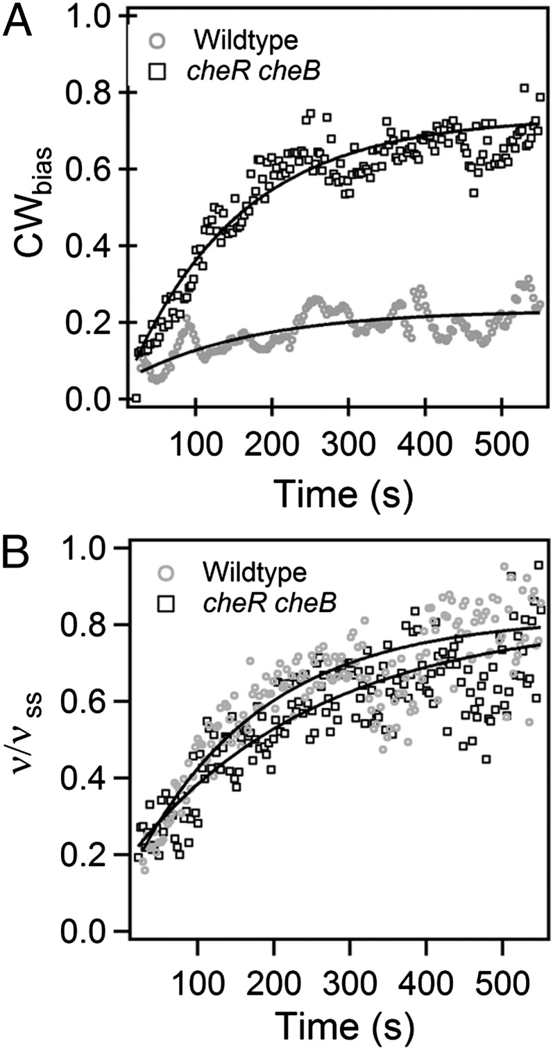
Kinetics of adaptation: (A) Adaptation in average CWbias. The solid curves are exponential fits to the data points. The rate constants are kcheRcheB ∼0.48 ± 0.00 min−1 (nine motors) and kWT ∼0.36 ± 0.01 min−1 (13 motors). (B) Adaptation in motor speed, with speeds normalized by the speeds at steady state. The solid curves are exponential fits to the data points. The rate constants are ξcheRcheB ∼0.30 ± 0.01 min−1 (nine motors) and ξWT ∼0.36 ± 0.01 min−1 (13 motors).
Mechanisms for Adaptation.
Exchange of motor force-generating units in E. coli was first shown in resurrection experiments, in which rotation of tethered cells of paralyzed mutants (motA or motB) was restored in a stepwise manner following expression of wild-type protein (14, 15). Stepwise recovery also was observed when cells were de-energized and then re-energized (after a pause of a few seconds) by application of an external voltage source (23), a procedure that has been updated using photorhodopsin (19). Continuous exchange of GFP–MotB also has been studied by fluorescence microscopy (17). Here, we have shown that exchange of force-generating units is load dependent. Our observations indicate that the number of stators driving the motor at a very low load is less than the number of stators driving the same motor at a high load; otherwise, motors would rotate at higher speeds immediately following a load increase. However, they start spinning at relatively low speeds (Movie S2).
When running near zero load, which occurs in a newly-assembled motor before the flagellum gets very long, a single force-generating unit drives the motor at full speed, and the proton flux is relatively high (assuming tight coupling): addition of more torque-generating units simply wastes protons. So there is economy in adding more force-generating units only as the flagellum grows (as mechanical load increases). Based on the frictional drag estimated near zero load (13), the torque applied by the stator on the rotor is estimated to be ∼10 pN-nm, which corresponds to a force of about 0.5 pN at the periphery of the rotor (∼20 nm radius). When the frictional drag on the motor is increased by adding a 1-μm bead, the same stator drives the motor at lower speeds (6–8 Hz) but delivers a higher torque ∼100–200 pN-nm or a force of about 5–10 pN on the rotor. This increment in torque generation is instantaneous and results in an equal and opposite force on the peptidoglycan layer in which the stator elements are anchored. Remodeling might arise because this increment in force causes conformational changes in neighboring binding sites or in the binding/unbinding properties of the stator elements themselves, increasing the probability of additional stator–element attachment, thereby boosting motor assembly (24). Such a mechanism might explain why stator elements operating at high loads leave the motor when the pmf is abolished (19, 23). In the absence of pmf, the stator elements no longer apply force to the peptidoglycan layer, and thus the binding sites might not remain open, promoting unbinding. This ability of the stator to detect changes in viscous loads (for example, during the growth of a flagellum) and recruit additional force-generating units to counter higher viscous drag is critical for bacterial motility.
In addition to changing the nature of the stator binding sites, the increase in torque delivered by stator elements also affects the switch in the rotor. Before the increase in load, the motor switches between CW and CCW directions of rotation. However, as shown in Figs. 1C and 4A, at short times following the load increase, the motor rotates predominantly CCW. Thus, an increase in torque experienced by the rotor predisposes it to remain in the CCW state, either by affecting the propensity of the FliG subunits to flip between the two conformations or by affecting CheY-P binding to FliM (or FliN). Subsequent addition of stator elements results in an increased overall torque on the rotor, and therefore the rotor experiences a greater resistance to switching to the CW state. However, it has been shown that FliM undergoes enhanced binding to the rotor in the CCW conformation (18). Such an increase in FliM content enhances CheY-P binding to the motor, allowing it to switch more often to the CW state. Therefore, it is possible that the increase in CW bias seen in Fig. 4 occurs due to an increase in the FliM content (or to the remodeling of other switch components, such as FliN).
The biophysical mechanism of the torque-generation process has remained elusive (25, 26). The torque versus speed relationship for the flagellar motor has been previously investigated over a wide range of loads (Fig. 1D). Theoretical models of the torque-generation process are tested by their ability to predict this relationship (25). However, theoretical models have assumed that the steady-state number of stators driving the motor remain constant over the entire torque–speed curve (26, 27). Our measurements prove otherwise; therefore, these results call for a revision of current models for a better understanding of the torque-generation process.
In Vibrio parahaemolyticus, mechanical inhibition of flagellar rotation leads to replacement of one kind of flagellum (polar) by another (lateral) (4). In Proteus mirabilis, mechanosensing by the motor has been proposed to play an important role in swarmer cell differentiation (5). Our results suggest that the stator senses the change in mechanical load and recruits additional stator elements in response. Because stator remodeling occurs within a few minutes following an increase in viscous load, it must therefore precede the series of steps that lead to swarmer-cell differentiation. How gene expression might be linked to stator conformation remains to be determined.
Materials and Methods
Strains and Plasmids.
Wild-type and cheY-deleted strains with sticky filaments (PL15 and PL4, respectively) were made by replacing fliC with the sticky fliC mutant in strains RP437 and HCB1284 (RP437 ∆cheY) by allele exchange (28). Replacing fliGWT with the fliGCW(∆PAA) mutant in PL4 yielded PL34 (∆cheY, fliGCW, sticky fliC), the CW-only fliG mutant strain. JY40 (cheR cheB fliM fliC) carrying pRWB7 (pTrc99A- fliM-eyfpA206K) and pKAF131 (sticky fliC under control of the native fliC promoter) was used to study load response in cheRcheB strains. For the eyfpA206K–motB fusion, 500 bp upstream of and including the first 84 bp of motB were fused to eyfp and cloned into pTrc99A (between restriction sites EcoR1 and Xba1). Next, the entire motB allele was cloned into the above plasmid (between restriction sites Xba1 and HindIII). Expression of the fusion in a nonmotile motB strain (HCB89) resulted in swimming cells. The fusion was subsequently exchanged with the genomic motBWT in the strain PL15 (yielding PL61). For control experiments with cells not subjected to shearing forces, HCB1671 (RP437, ∆fliC) was used. For testing the role of FliL in mechanosensing, strain PL62 was constructed from PL15 by deleting fliL sequence coding for aa 21–135, based on previous work (21). The deletion was confirmed by DNA sequencing (Eurofins MWC Operon). Strains were grown and prepared as described previously (8).
TIRF Measurements of YFP–MotB.
The flagella of cells were sheared to filament stubs as described previously (29), and the TIRF setup and experiments are described elsewhere (18). Photobleaching made visualization of stator addition difficult, as the addition of new stators to the already present photobleached stators would not necessarily result in intensity increments. Hence, imaging sequences were spaced ∼5 min apart to allow sufficient time for the previously photobleached molecules to be replaced with the unbleached membranous YFP–MotB molecules. This method was preferred over approaches that correct for photobleaching during acquisition (30), because such models would require assumptions of MotB exchange dynamics over varying motor torque. Only those cells that rotated upon tethering without pausing were selected for data analysis. Not all YFP–MotB motors showed distinct step increments in speeds. This was because the YFP fusion likely interferes with the power-stroke mechanism, which also prevents YFP–MotB motors from reaching full speeds expected for tethered cells.
Optical Tweezer Assay.
We modified the laser dark-field microscope (the bead tracker) used earlier for following the rotation of beads (13) by adding a dichroic mirror above the objective (Nikon Plan Apochromat 60×, NA 1.20, water-immersion objective with cover glass correction collar) to bring in light for an optical trap (31). Details of bead and tethered-cell tracking and the step algorithms are detailed in SI Text.
Supplementary Material
Acknowledgments
We thank K. A. Fahrner for helpful discussions. This work was supported by National Institutes of Health Grant AI016478.
Footnotes
The authors declare no conflict of interest.
This article is a PNAS Direct Submission.
This article contains supporting information online at www.pnas.org/lookup/suppl/doi:10.1073/pnas.1305885110/-/DCSupplemental.
References
- 1.Engler AJ, Sen S, Sweeney HL, Discher DE. Matrix elasticity directs stem cell lineage specification. Cell. 2006;126(4):677–689. doi: 10.1016/j.cell.2006.06.044. [DOI] [PubMed] [Google Scholar]
- 2.Gebhardt JC, Rief M. Biochemistry. Force signaling in biology. Science. 2009;324(5932):1278–1280. doi: 10.1126/science.1175874. [DOI] [PubMed] [Google Scholar]
- 3.Kearns DB. A field guide to bacterial swarming motility. Nat Rev Microbiol. 2010;8(9):634–644. doi: 10.1038/nrmicro2405. [DOI] [PMC free article] [PubMed] [Google Scholar]
- 4.Gode-Potratz CJ, Kustusch RJ, Breheny PJ, Weiss DS, McCarter LL. Surface sensing in Vibrio parahaemolyticus triggers a programme of gene expression that promotes colonization and virulence. Mol Microbiol. 2011;79(1):240–263. doi: 10.1111/j.1365-2958.2010.07445.x. [DOI] [PMC free article] [PubMed] [Google Scholar]
- 5.Rather PN. Swarmer cell differentiation in Proteus mirabilis. Environ Microbiol. 2005;7(8):1065–1073. doi: 10.1111/j.1462-2920.2005.00806.x. [DOI] [PubMed] [Google Scholar]
- 6.McCarter L, Hilmen M, Silverman M. Flagellar dynamometer controls swarmer cell differentiation of V. parahaemolyticus. Cell. 1988;54(3):345–351. doi: 10.1016/0092-8674(88)90197-3. [DOI] [PubMed] [Google Scholar]
- 7.Hazelbauer GL, Falke JJ, Parkinson JS. Bacterial chemoreceptors: High-performance signaling in networked arrays. Trends Biochem Sci. 2008;33(1):9–19. doi: 10.1016/j.tibs.2007.09.014. [DOI] [PMC free article] [PubMed] [Google Scholar]
- 8.Yuan J, Branch RW, Hosu BG, Berg HC. Adaptation at the output of the chemotaxis signalling pathway. Nature. 2012;484(7393):233–236. doi: 10.1038/nature10964. [DOI] [PMC free article] [PubMed] [Google Scholar]
- 9.Tu Y, Berg HC. Tandem adaptation with a common design in Escherichia coli chemotaxis. J Mol Biol. 2012;423(5):782–788. doi: 10.1016/j.jmb.2012.08.012. [DOI] [PMC free article] [PubMed] [Google Scholar]
- 10.Shimizu TS, Delalez N, Pichler K, Berg HC. Monitoring bacterial chemotaxis by using bioluminescence resonance energy transfer: Absence of feedback from the flagellar motors. Proc Natl Acad Sci USA. 2006;103(7):2093–2097. doi: 10.1073/pnas.0510958103. [DOI] [PMC free article] [PubMed] [Google Scholar]
- 11.Chen XB, Berg HC. Torque-speed relationship of the flagellar rotary motor of Escherichia coli. Biophys J. 2000;78(2):1036–1041. doi: 10.1016/S0006-3495(00)76662-8. [DOI] [PMC free article] [PubMed] [Google Scholar]
- 12.Yuan J, Berg HC. Resurrection of the flagellar rotary motor near zero load. Proc Natl Acad Sci USA. 2008;105(4):1182–1185. doi: 10.1073/pnas.0711539105. [DOI] [PMC free article] [PubMed] [Google Scholar]
- 13.Yuan J, Fahrner KA, Berg HC. Switching of the bacterial flagellar motor near zero load. J Mol Biol. 2009;390(3):394–400. doi: 10.1016/j.jmb.2009.05.039. [DOI] [PMC free article] [PubMed] [Google Scholar]
- 14.Block SM, Berg HC. Successive incorporation of force-generating units in the bacterial rotary motor. Nature. 1984;309(5967):470–472. doi: 10.1038/309470a0. [DOI] [PubMed] [Google Scholar]
- 15.Blair DF, Berg HC. Restoration of torque in defective flagellar motors. Science. 1988;242(4886):1678–1681. doi: 10.1126/science.2849208. [DOI] [PubMed] [Google Scholar]
- 16.Reid SW, et al. The maximum number of torque-generating units in the flagellar motor of Escherichia coli is at least 11. Proc Natl Acad Sci USA. 2006;103(21):8066–8071. doi: 10.1073/pnas.0509932103. [DOI] [PMC free article] [PubMed] [Google Scholar]
- 17.Leake MC, et al. Stoichiometry and turnover in single, functioning membrane protein complexes. Nature. 2006;443(7109):355–358. doi: 10.1038/nature05135. [DOI] [PubMed] [Google Scholar]
- 18.Lele PP, Branch RW, Nathan VS, Berg HC. Mechanism for adaptive remodeling of the bacterial flagellar switch. Proc Natl Acad Sci USA. 2012;109(49):20018–20022. doi: 10.1073/pnas.1212327109. [DOI] [PMC free article] [PubMed] [Google Scholar]
- 19.Tipping MJ, Steel BC, Delalez NJ, Berry RM, Armitage JP. Quantification of flagellar motor stator dynamics through in vivo proton-motive force control. Mol Microbiol. 2013;87(2):338–347. doi: 10.1111/mmi.12098. [DOI] [PubMed] [Google Scholar]
- 20.Kojima S, Blair DF. Conformational change in the stator of the bacterial flagellar motor. Biochemistry. 2001;40(43):13041–13050. doi: 10.1021/bi011263o. [DOI] [PubMed] [Google Scholar]
- 21.Attmannspacher U, Scharf BE, Harshey RM. FliL is essential for swarming: Motor rotation in absence of FliL fractures the flagellar rod in swarmer cells of Salmonella enterica. Mol Microbiol. 2008;68(2):328–341. doi: 10.1111/j.1365-2958.2008.06170.x. [DOI] [PubMed] [Google Scholar]
- 22.Cusick K, Lee YY, Youchak B, Belas R. Perturbation of FliL interferes with Proteus mirabilis swarmer cell gene expression and differentiation. J Bacteriol. 2012;194(2):437–447. doi: 10.1128/JB.05998-11. [DOI] [PMC free article] [PubMed] [Google Scholar]
- 23.Fung DC, Berg HC. Powering the flagellar motor of Escherichia coli with an external voltage source. Nature. 1995;375(6534):809–812. doi: 10.1038/375809a0. [DOI] [PubMed] [Google Scholar]
- 24.Chan YH, Marshall WF. How cells know the size of their organelles. Science. 2012;337(6099):1186–1189. doi: 10.1126/science.1223539. [DOI] [PMC free article] [PubMed] [Google Scholar]
- 25.Berg HC. The rotary motor of bacterial flagella. Annu Rev Biochem. 2003;72:19–54. doi: 10.1146/annurev.biochem.72.121801.161737. [DOI] [PubMed] [Google Scholar]
- 26.Meacci G, Lan G, Tu Y. Dynamics of the bacterial flagellar motor: The effects of stator compliance, back steps, temperature, and rotational asymmetry. Biophys J. 2011;100(8):1986–1995. doi: 10.1016/j.bpj.2011.02.045. [DOI] [PMC free article] [PubMed] [Google Scholar]
- 27.Xing J, Bai F, Berry R, Oster G. Torque-speed relationship of the bacterial flagellar motor. Proc Natl Acad Sci USA. 2006;103(5):1260–1265. doi: 10.1073/pnas.0507959103. [DOI] [PMC free article] [PubMed] [Google Scholar]
- 28.Datsenko KA, Wanner BL. One-step inactivation of chromosomal genes in Escherichia coli K-12 using PCR products. Proc Natl Acad Sci USA. 2000;97(12):6640–6645. doi: 10.1073/pnas.120163297. [DOI] [PMC free article] [PubMed] [Google Scholar]
- 29.Block SM, Segall JE, Berg HC. Impulse responses in bacterial chemotaxis. Cell. 1982;31(1):215–226. doi: 10.1016/0092-8674(82)90421-4. [DOI] [PubMed] [Google Scholar]
- 30.Wu J, Shekhar N, Lele PP, Lele TP. FRAP analysis: Accounting for bleaching during image capture. PLoS ONE. 2012;7(8):e42854. doi: 10.1371/journal.pone.0042854. [DOI] [PMC free article] [PubMed] [Google Scholar]
- 31.Berry RM, Berg HC. Absence of a barrier to backwards rotation of the bacterial flagellar motor demonstrated with optical tweezers. Proc Natl Acad Sci USA. 1997;94(26):14433–14437. doi: 10.1073/pnas.94.26.14433. [DOI] [PMC free article] [PubMed] [Google Scholar]
Associated Data
This section collects any data citations, data availability statements, or supplementary materials included in this article.