Abstract
The lack of readily available sterilization processes for medicine and dentistry practices in the developing world is a major risk factor for the propagation of disease. Modern medical facilities in the developed world often use autoclave systems to sterilize medical instruments and equipment and process waste that could contain harmful contagions. Here, we show the use of broadband light-absorbing nanoparticles as solar photothermal heaters, which generate high-temperature steam for a standalone, efficient solar autoclave useful for sanitation of instruments or materials in resource-limited, remote locations. Sterilization was verified using a standard Geobacillus stearothermophilus-based biological indicator.
Keywords: nanoscience, nanoshells, plasmon, energy conversion
According to the World Health Organization, healthcare-associated infections are the most prevalent adverse consequence of medical treatment worldwide (1–3). Although this problem is disconcerting and costly in developed countries, its impact in developing regions is devastating (4). More than one-quarter of the human population worldwide lacks access to electricity, let alone the high power requirements necessary for modern sterilization systems. Because more than one-half of all people in developing regions lack access to all-weather roads, the channeling of a consistent supply of disposable sterilizing resources into these areas presents an even more daunting challenge (5). Consequently, addressing the problem of resource-constrained sterilization can be viewed as an effort to provide solutions to both power and supply chain constraints.
The underlying cause of healthcare-associated (nosocomial) infections is prolonged or focused exposure to unsanitary conditions. Such conditions can be ameliorated through the use of sanitation and sterilization methods. Sterilization involves the destruction of all microorganisms and their spores, whereas disinfection is a less robust process that involves the removal of microorganisms without complete sterilization (6). One of the simplest, most effective, and most reliable approaches for the sterilization of medical devices and materials is the use of an autoclave. The fundamental concept of an autoclave is to expose the media to be sterilized to saturated steam at an elevated temperature. On coming into contact with the medium to be sterilized, the saturated steam condenses from the gas phase to the liquid phase, transferring its latent heat of vaporization to the material to be sterilized and thus, any associated microbes on its surface. Such a rapid transfer of heat is extremely effective for denaturing proteins and may be used to destroy most known types of infectious agents, including bacteria, viruses, or viral spores.
Steam-based autoclave systems neutralize potentially infectious microorganisms localized on solid surfaces or in liquid-phase media by exposing them to high-temperature pressurized steam. The process of steam sterilization relies on both steam temperature and time duration of steam exposure to ensure irreversible destruction of all microorganisms, especially bacterial endospores, which are considered particularly thermally stable. Although steam-based sterilization is the primary method of choice for the processing of medical waste in the developed world, the large energy requirement for operation is the fundamental limitation for its adoption in developing countries, with limited or nonexistent access to sources of electricity sufficient to power such systems.
Recently, we reported the use of broadband light-absorbing particles for solar steam generation (7). A variety of nanoparticles such as metallic nanoshells, nanoshell aggregates, and conductive carbon nanoparticles, when dispersed in aqueous solution and illuminated by sunlight, has been shown to convert absorbed solar energy to steam at an efficiency of just over 80%, where less than 20% of the energy contributes to heating the liquid volume (7). This effect depends on the highly localized, strong photothermal response of these types of nanoparticles, a characteristic that is being used to effectively ablate solid tumors by irradiation with near-IR laser light with near-unity tumor remission rates (8–16). In the solar steam generation process, broadband light-absorbing nanoparticles create a large number of nucleation sites for steam generation within the fluid. As light is absorbed by a nanoparticle, a temperature difference between the nanoparticle and the surrounding fluid is established because of a reduced thermal conductivity at the metal–liquid interface: this local temperature increase may become sufficient to transform the liquid in the direct vicinity of the nanoparticle into vapor. On sustained illumination, the vapor envelope surrounding the nanoparticle grows, eventually resulting in buoyancy of the nanoparticle–bubble complex. When this complex reaches the surface of the liquid, the vapor is released, resulting in vigorous nonequilibrium steam generation that does not require the bulk fluid temperature to have reached its boiling point. If the fluid is kept in an ice bath, steam is produced, even when the fluid temperature remains at 0 °C (7). Over prolonged exposure to sunlight, however, both the more-efficient process of nanoparticle-based steam generation and the less-efficient process of bulk fluid heating occur, eventually resulting in simultaneous nanoparticle-based steam generation and boiling of the bulk fluid. The combination of these two processes results in solar steam production that occurs at higher steam temperatures than can be achieved using nonparticle-based fluid heating (Fig. 1). The nanoparticles are neither dispersed into the vapor phase nor degraded by the steam generation process.
Fig. 1.
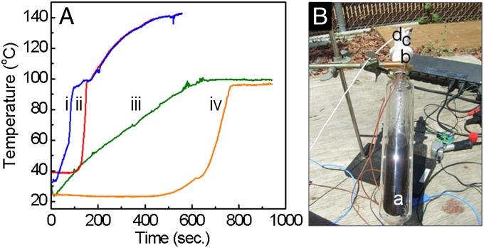
Temperature evolution of solar steam generation. (A) Temperature vs. time for Au nanoshell-dispersed water (i, liquid; ii, vapor) and water without nanoparticles (iii, liquid; iv, vapor) under solar exposure. (Au nanoparticle concentration sufficient to produce an optical density of unity.) (B) Photograph of system used in the temperature evolution of solar steam generation: (a) transparent vessel isolated with a vacuum jacket to reduce thermal losses, (b) two thermocouples for sensing the solution and the steam temperature, (c) pressure sensor, and (d) 1/16-in nozzle.
The temperature–time evolution of the nanoparticle-dispersed fluid and steam produced during solar irradiation is shown in Fig. 1A with and without the presence of nanoparticles. A detailed characterization of the nanoparticles is shown in Fig. S1. With nanoparticle dispersants, temperatures of both the liquid and the steam increase far more rapidly than the temperature of pure water (Fig. 1A, i and ii), with the liquid water reaching 100 °C more rapidly with nanoparticle dispersants than water without nanoparticles. Measurable steam production occurs at a lower water temperature for the case with nanoparticle dispersants, because nanoparticle-dispersed steam generation can occur at any fluid temperature. For the case shown here, measurable steam production appears at a water temperature of ∼70 °C, well below the steam production threshold for pure water. Perhaps most importantly, however, is the large difference in steady-state temperature achieved for the two systems: with the inclusion of nanoparticle dispersants, the temperature of both the water and the vapor increase well above the standard boiling point of water. In this case, an equilibrium temperature of 140 °C is easily achieved in the nanoparticle-dispersed water–steam system. This elevated temperature enables the use of nanoparticle-generated solar steam for medical sterilization applications.
The evolution of solar steam generation from Au nanoshells dispersed in water was quantified in an open-loop system (Fig. 1B) consisting of a 200-mL vessel isolated with a vacuum jacket to prevent heat loss, a pressure sensor, and two thermocouples to monitor both the liquid and vapor temperatures. The vessel was illuminated with solar radiation focused by a 0.69-m2 Fresnel lens into the glass vessel containing 100 mL nanoparticles at a concentration of 1010 particles/m3 or alternatively, water with no nanoparticles as a control. On solar illumination, vapor was allowed to escape through a 16-µm-diameter nozzle, while the pressure and temperature were recorded.
Here, we show two different compact solar autoclaves driven by nanoparticle-based solar steam generation that are well-suited to off-grid applications. Using a solar concentrator (Fresnel lens or dish mirror) to deliver sunlight into the nanoparticle-dispersed aqueous working fluid, this process is capable of delivering steam at a temperature of 115–135 °C into a 14.2-L volume for a time period sufficient for sterilization. Sterilization was verified using a standard Geobacillus stearothermophilus-based biological indicator.
Experimental Section
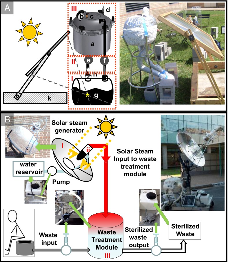
Two solar sterilization designs have been developed. One is a portable, closed-loop solar autoclave system suitable for sterilization of medical or dental tools; the second design is a solar dish collector autoclave system that can serve as a standalone, off-grid steam source suitable for human or animal waste sterilization systems or other applications. Steam from the closed-loop system (Fig. 2A) is produced under solar illumination, transported into the sterilization volume, condensed, and then delivered back into the fluid vessel. The design consists of three main subsystems: the steam generation module (Fig. 2A, I), the connection module (Fig. 2A, II), and the sterilization module (Fig. 2A, III). More detailed schematics of the system are presented in Figs. S1, S2, and S3.
Fig. 2.
(A) Schematic and photograph of the closed-loop solar autoclave showing (I) the steam generation module, (II) the connection module, and (III) the sterilization module. The components of the system are (a) sterilization vessel, (b) pressure sensor, (c) thermocouple sensor, (d) relief valve, (e and f) control valves, (g) solar collector containing the nanoparticle-based heater solution, (h) check valve, and (k) solar concentrator (a plastic Fresnel lens of 0.67-m2 surface area). (B) Schematic and photograph of the open-loop solar autoclave: the components of the system are (i) solar concentrator (44-in dish mirror), (ii) heat collector containing metallic nanoparticles, and (iii) sterilization vessel that contains a pressure sensor, two thermocouple sensors, a steam relief valve, and two hand pumps and valves that control the input and output of waste. The solar concentrator dish system has a dual tracking system powered by a small car battery recharged by a solar cell unit.
The particle solution is contained in a custom-built insulated glass vessel with two inlets that lead to the connection module. Solar collection is accomplished with a relatively small and inexpensive Fresnel lens. The hot solar steam generated within this module is channeled out one nozzle of the connection module into the sterilization module, where it condenses on the objects to be sterilized, returning as condensate to the steam generation module. A check valve at one port of the steam generation module ensures a unidirectional flow of steam throughout the entire system.
The sterilization module consists of an insulated pressure vessel (a converted stovetop autoclave with a 14.2-L capacity). A condensate return hole (diameter of 0.86 cm) was milled on the bottom face of the autoclave vessel 10 cm away from the center. Similarly, a steam inlet hole (diameter of 0.86 cm) was milled on the lid of the sterilizing vessel 10 cm away from the center. A finite element analysis (SolidWorks using the Tresca maximum) was performed to identify the mechanically weakest portions of the pressure vessel when placed under high-stress conditions (Fig. S3). By varying the radial position of the hole in the base of the pressure vessel, a minimum factor of safety (vessel material strength/design load) under many different machining configurations was determined. A 0.86-cm-diameter hole positioned 10 cm from the center of the pressure vessel was determined to be the optimal location, with a minimum factor of safety of 3.35. To minimize heat losses from the steam generation module and the sterilization module, the system was insulated with a sealant (Great Stuff Fireblock Insulating Foam Sealant) applied to the surfaces of the vessels and covered with aluminum foil to further minimize heat loss.
The connection module consists of two parts: the steam connection, which allows steam to flow from the steam generation module to the sterilization module, and the condensate connection, which returns the condensate from the sterilization module (Fig. S3). The steam connection consists of polytetrafluoroethylene (PTFE) tubing insulated in fiberglass pipe wrap and a ball valve; the condensate connection consists of a ball valve, PTFE tubing insulated in fiberglass pipe wrap, a check valve, and a pressure release valve. Both units contain an adaptor to connect to the steam generation module.
The solar-generated steam enters the sterilization module at the top of the vessel, forcing the unsterile air down and out of the vessel through the air exhaust tube, which is connected to the control valve. Trapped unsterile air can have an insulating effect and prevent complete sterilization; therefore, it is critical that as much air as possible be removed from the sterilization module. After the unsterile air is purged from the system, the control valve is closed to allow pressure to build up in the vessel. The cycle is maintained at a minimum of 115 °C and 12 psig and a maximum of 140 °C and 20 psig in all regions of the sterilization module throughout the duration of a sterilization cycle. The condensate is channeled back to the steam generation module by a check valve when the hydrostatic pressure exceeds the maximum pressure of the valve (rated at 0.3 psi).
An optimized, open-loop, prototypical compact solar autoclave for human waste sterilization is presented in Fig. 2B. Using a 44-in solar dish collector to focus sunlight into the nanoparticle-dispersed aqueous working fluid, we deliver steam into a 14.2-L capacity sterilization volume (a commercially available stovetop autoclave). This volume could easily accommodate the 10-L capacity volume of a mobile sanitation (moSAN) toilet, for example (a personal-use toilet designed for Deutsche Gesellschaft für Internationale Zusammenarbeit GmbH and originally developed for the urban poor in Bangladesh), and if operated three times per week, it could process the weekly amount of both solid and liquid waste produced by a household of four adults (∼35 L). Solar energy is supplied to this unit through a reflective parabolic dish that tracks the sun, is powered by a small car battery, and is rechargeable with a small solar panel. The generated steam is transmitted to the autoclave through silicon tubing. Unprocessed waste is delivered to the autoclave by means of a mechanical hand pump, which can be easily operated by a single person. After the sterilization process, the sanitized waste is removed by gravity. Because of its simple, modular design, the system can easily be expanded to provide high-temperature steam for larger-scale applications.
The nanoparticle solution is contained in a custom-designed vacuum-insulated vessel positioned at the focus of the parabolic reflector. The steam generated within this module is channeled into the waste sterilization module. Under typical operation, the steam temperature is maintained at 132 °C for 5 min, the duration of time required for an International Organization for Standardization (ISO) standard sterilization cycle. The steam temperature was monitored at the output of the steam generation module, and the waste solution temperature was monitored inside the sterilization module. These two locations are expected to reach the sterilization temperature with slight thermal (gas and liquid phases) differences inside the sterilization module during the sterilization process.
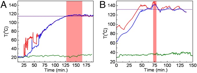
The steam temperature was monitored in both geometries at the steam connection and the condensate connection directly adjacent to the sterilization module. These two locations are expected to have the highest and lowest steam temperatures, respectively, allowing us to measure the overall temperature gradient generated inside the sterilization module during the sterilization process. The steam temperature before and during a sterilization cycle is shown in Fig. 3.
Fig. 3.

The autoclave temperature distribution of the (A) closed-loop and (B) open-loop solar autoclaves. The temperature of steam vs. time measured in two different locations in autoclave: top (red curve) and respective bottom (blue curve). The dashed line indicates temperature required for sterilization, and the red box indicates the sterilization regime (115 °C for 20 min or 132 °C for 4.6 min). The ambient temperature (green) was monitored as reference.
The red curve in Fig. 3 is the temperature of the steam at the inlet valve to the sterilization vessel, the blue curve in Fig. 3 is the temperature of the condensate at the sterilization vessel output, and the ambient temperature in Fig. 3 is the green curve. The dashed gray line in Fig. 3 represents the temperature required for sterilization (115–132 °C). In the case of the closed-loop system (Fig. 3A), the irregular spikes in the temperature curves correspond to when the steam begins to enter the vessel. The bottom thermocouple shows two major spikes during warm-up that are generated by the release of unsterilized air from the sterilization module. The first spike induced turbulence into the system, which exposed the thermocouple briefly to hotter steam. The second jump in the temperature data of the output thermocouple corresponds to the release of the remaining unsterilized insulated air. The monitoring data clearly show that the autoclave is easily capable of maintaining a temperature over 115 °C for more than 30 min of the sterilization time required at that temperature. In the case of the open-loop system (Fig. 3B), the red curve is the gas temperature of the steam measured at the vessel inlet valve, the blue curve is the temperature inside the vessel contents (artificial fecal material), and the ambient temperature is the green curve. The dashed gray line represents the desired temperature required for sterilization (132 °C). After an initial ramp-up period of ∼20 min, the sterilization temperature is reached, and the temperature–time curve continues to oscillate around this value because of the frequent release of steam from the sterilization vessel through the pressure safety valve. The solar thermal evolution data show that the autoclave is capable of maintaining a temperature around 132 °C for more than 5 min.
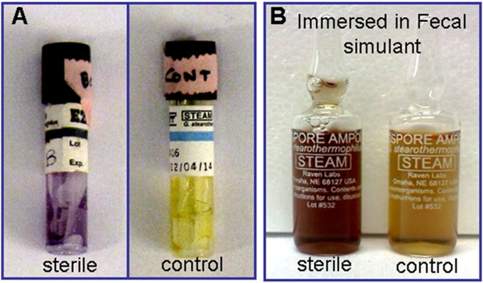
To test whether our systems can achieve the Sterility Assurance Level defined by the Food and Drug Administration (17), we operated the system through a cycle with the sterilization vessel containing commercial biological indicator strips for G. stearothermophilus (EZTest Self-Contained Biological Indicator Strips; SGM Biotech), a reference strain commonly used for sterilization testing. The test strips were secured in the sterilization module near the inlet stream and outlet stream taps or immersed in a fecal simulator solution. After completion of the cycle, the strips were incubated for 36 h at 55–60 °C. The results are shown in Fig. 4.
Fig. 4.
Biological indicators used to test solar autoclave sterilization. Test vials of G. stearothermophilus placed in various locations in the sterilization module: (A) the top/bottom of vessels were sealed for solid material and unprocessed control and (B) placed in fecal stimulant sealed for liquid–solid material and unprocessed control. They were used to test solar autoclave sterilization. The sterilization is confirmed by color change of vial contents.
The color change shown by the vials in Fig. 4, relative to the control vial, indicates that sterilization is achieved by operating the solar autoclave through one 30-min cycle at 115 °C for the closed-loop system and one 5-min cycle at 132 °C for the open-loop system. If some spores survive a sterilization cycle, the biological indicator culture medium undergoes a color change from purple to yellow. The observed color change indicates that spore survival did not occur.
In conclusion, we have shown two compact solar autoclaves enabled by solar steam generation using broadband, light-absorbing nanoparticles. The systems maintain temperatures between 115 °C and 132 °C for the time period sufficient to sterilize the contents of a 14.2-L volume, which is in accordance with Food and Drug Administration sterilization requirements. Using a parabolic dish solar collector enables a faster heat-up time and higher operating temperatures, which shorten the sterilization cycle time significantly (from 15 min at 121 °C to 5 min at 132 °C). The nanoparticles are not consumed by the heating process and can be reused indefinitely; the only consumable is water, which need not be sterilized before use. This type of system can easily be expanded to provide direct steam generation for additional applications, which may include distillation-based water purification, cooking, waste remediation, or electricity generation.
Figs. S1, S2, and S3 show extensive schematics of the configuration system and characterizations of metallic nanostructures.
Supplementary Material
Acknowledgments
We thank Jared Day, Alexander Urban, Christyn A. Thibodeaux, and Surbhi Lal for helpful discussions and Robert A. Welch Foundation Grants C-1220 and C-1222 and the Bill and Melinda Gates Foundation for financial support.
Footnotes
The authors declare no conflict of interest.
This article contains supporting information online at www.pnas.org/lookup/suppl/doi:10.1073/pnas.1310131110/-/DCSupplemental.
References
- 1. World Health Organization (2010) The Burden of Health Care-Associated Infection Worldwide. Available at http://www.who.int/gpsc/country_work/burden_hcai/en/index.html. Accessed June 18, 2013.
- 2. World Health Organization (2002) Prevention of Hospital-Acquired Infections: A Practical Guide. Available at http://apps.who.int/medicinedocs/documents/s16355e/s16355e.pdf. Accessed June 18, 2013.
- 3. World Health Organization (2010) Solar Powered Autoclaves in Low Resource Settings. Available at www.who.int/medical_devices/poster_a18.pdf. Accessed June 18, 2013.
- 4.Orrett FA, Brooks PJ, Richardson EG. Nosocomial infections in a rural regional hospital in a developing country: Infection rates by site, service, cost, and infection control practices. Infect Control Hosp Epidemiol. 1998;19(2):136–140. doi: 10.1086/647781. [DOI] [PubMed] [Google Scholar]
- 5. Pacific UNEaSCfAat (2006) Transport Infrastructure. Available at http://www.unescap.org/pdd/publications/themestudy2006/9_ch3.pdf. Accessed June 18, 2013.
- 6.Rutala WA, Weber DJ, Healthcare Infection Control Practices Advisory Committee (HICPAC) (2008) Guideline for Disinfection and Sterilization in Healthcare Facilities. (Center for Disease Control and Prevention, Atlanta). Available at www.cdc.gov/hicpac/pdf/guidelines/disinfection_nov_2008.pdf. Accessed June 18, 2013. [Google Scholar]
- 7.Neumann O, et al. Solar vapor generation enabled by nanoparticles. ACS Nano. 2013;7(2013):42–49. doi: 10.1021/nn304948h. [DOI] [PubMed] [Google Scholar]
- 8.Govorov AO, Richardson HH. Generating heat with metal nanoparticles. Nano Today. 2007;2(1):30–38. [Google Scholar]
- 9.Huhn D, Govorov A, Gil PR, Parak WJ. Photostimulated au nanoheaters in polymer and biological media: Characterization of mechanical destruction and boiling. Adv Funct Mat. 2012;22(2):294–303. [Google Scholar]
- 10.Richardson HH, Carlson MT, Tandler PJ, Hernandez P, Govorov AO. Experimental and theoretical studies of light-to-heat conversion and collective heating effects in metal nanoparticle solutions. Nano Lett. 2009;9(3):1139–1146. doi: 10.1021/nl8036905. [DOI] [PMC free article] [PubMed] [Google Scholar]
- 11.Hirsch LR, et al. Nanoshell-mediated near-infrared thermal therapy of tumors under magnetic resonance guidance. Proc Natl Acad Sci USA. 2003;100(23):13549–13554. doi: 10.1073/pnas.2232479100. [DOI] [PMC free article] [PubMed] [Google Scholar]
- 12.O’Neal DP, Hirsch LR, Halas NJ, Payne JD, West JL. Photo-thermal tumor ablation in mice using near infrared-absorbing nanoparticles. Cancer Lett. 2004;209(2):171–176. doi: 10.1016/j.canlet.2004.02.004. [DOI] [PubMed] [Google Scholar]
- 13.Huang X, Jain PK, El-Sayed IH, El-Sayed MA. Plasmonic photothermal therapy (PPTT) using gold nanoparticles. Lasers Med Sci. 2008;23(3):217–228. doi: 10.1007/s10103-007-0470-x. [DOI] [PubMed] [Google Scholar]
- 14.Lal S, Clare SE, Halas NJ. Nanoshell-enabled photothermal cancer therapy: impending clinical impact. Acc Chem Res. 2008;41(12):1842–1851. doi: 10.1021/ar800150g. [DOI] [PubMed] [Google Scholar]
- 15.Lee JY, Peumans P. The origin of enhanced optical absorption in solar cells with metal nanoparticles embedded in the active layer. Opt Express. 2010;18(10):10078–10087. doi: 10.1364/OE.18.010078. [DOI] [PubMed] [Google Scholar]
- 16.Otanicar TP, Phelan PE, Prasher RS, Rosengarten G, Taylor RA. Nanofluid-based direct absorption solar collector. J Renew Sustainable Energy. 2010;2(3):033102–033113. [Google Scholar]
- 17. Branch ICD (1993) Guidance on Premarket Notification [510(k)] Submissions for Sterilizers Intended for Use in Health Care Facilities. Available at http://www.fda.gov/downloads/MedicalDevices/DeviceRegulationandGuidance/GuidanceDocuments/UCM081341.pdf. Accessed June 18, 2013.
Associated Data
This section collects any data citations, data availability statements, or supplementary materials included in this article.


