

Abstract
In high speed rotating machines such as turbines and generators, vibrations of a rotating shaft often hinder the smooth operation of the machine or even cause failure. Oil whip is one of such vibrations due to oil film action of journal bearing. Its mechanism and preventive method is explained and proposed in this paper. Further theoretical and experimental analyses are made for considering heat generation and temperature rise in hydrodynamic lubrication. The usefulness of the lubrication theory based on the k–ε model is also shown for bearings with high eccentricity ratios. In the latter half of this paper, water lubrication, nitrogen gas lubrication and tribo-coated indium lubrication are shown as new promising methods, and their mechanisms are discussed and the importance of tribo-layer is explained. Some mechanisms of wear are introduced for better understanding of tribo-layer. In the last part of this paper, the mechanisms of generating static friction are shown for the cases of plastic contact and elastic contact, which is the base for understanding the mechanism of initiation of macroscopic sliding.
Keywords: journal bearing, oil whip, hydrodynamic lubrication, k–ε model, heat generation, temperature rise, water lubrication, nitrogen lubrication, tribo-coated indium lubrication, tribo-layer, wear, static friction
1. Introduction
Tribology is a word first used in Jost Report of the British Department of Education and Science in 1966. Its definition is as follows:
Tribology is the science and technology of interacting surfaces in relative motion and of the practices related thereto.
Therefore, tribology covers all the fields of friction, wear and lubrication. It is from Greek tribos which means rubbing.
The friction law between solid surfaces was studied by Leonardo da Vinci and later by Amonton and Coulomb, and its empirical law was established by the year 1800. Its qualitative explanation was given in 1920–50 by Bowden and Tabor using the adhesion theory of micro asperity junctions. The mechanism of hydrodynamic lubrication which is necessary for reducing friction was experimentally clarified by Tower in 1883 and was mathematically formulated by Reynolds in 1886. Many lubrication problems have been solved since then by using Reynolds’ theory, including the lubrication analysis of reciprocating bearings by Yokobori in 1945.
On the other hand, rotating machinery, the speed of which increased rapidly in the first half of 20th century, faced the problem of violent vibrations of a shaft (oil whip) at a rotary speed of the shaft over twice the critical speed due to the oil film action of the bearings and this prohibited the increase in speed and length of shafts for many years. In the same period, machines began to face the strong demand of high reliability for their higher ability and complexity. As a result, studies on the wear law of solids became active rapidly, and the confirmation of the macroscopic wear law and the understanding of microscopic mechanisms were problems to be solved. The necessity of unifying science and technology related to friction, wear and lubrication was strongly recognized, and finally a new word “tribology” was introduced as an interdisciplinary concept as stated above.
In this paper, some recent achievements by the authors in hydrodynamic lubrication and those in friction, wear and solid lubrication will be explained.
2. Hydrodynamic lubrication
Hori, one of the authors, has been interested in various problems in the hydrodynamic lubrication such as stability of rotating shafts in journal bearings,1),2) foil bearings,3) sinusoidal squeeze films,4) heat generation5),6) and turbulence7) in the lubricating films. See the Ref. 8.
In the following, stability of rotating shafts in journal bearings and some related problems will be discussed with special emphasis on oil whip. Seismic effect on oil whip will also be discussed. Heat generation and turbulence will be referred to very briefly.
2.1. Stability of a rotating shaft in journal bearings
2.1.1. Oil whip
In high speed rotating machines such as turbines and generators, vibrations of a rotating shaft often hinder the smooth operation of the machine or even cause failure. Oil whip is one of such vibrations due to the oil film action of journal bearings. Oil whip was first reported by Newkirk and Taylor as a new kind of severe vibrations at speeds over twice the critical speed of the shaft (1925).9) Since the vibration disappeared when oil supply was stopped and it resumed when the oil was supplied again, they concluded that the vibration was caused by the oil film in the bearing and named it oil whip.
The phenomenon will be described in more detail in Fig. 1.
Fig. 1.

Oil whip.
When the rotating speed of a shaft is gradually increased from zero, a large resonant vibration occurs in the shaft at the critical speed ω1. The vibration diminishes, however, when the rotating speed passes the critical speed. Then, when twice the critical speed 2ω1 is reached, a large vibration (or whirling) will occur as shown in Fig. 1 under certain conditions. When the shaft speed is increased further, this vibration will not diminish but may continue as it was or it may become even larger, unlike resonant vibrations. This is typical of oil whip.
The features of oil whip are summarized as follows:
When the shaft speed is raised from zero, oil whip starts in many cases at twice the critical speed and continues to exist beyond that speed.
The whirling speed of oil whip is almost constant and equal to the critical speed.
The whirling direction is the same as that of the shaft rotation.
Oil whip occurs easily when the journal floats up easily.
Below twice the critical speed, the shaft may sometimes whirl quietly with little shaft bending. The whirling speed in this case is equal to one-half of its rotational speed (proportional to the rotational). This is called oil whirl or half-speed whirl.
Later, Newkirk and Lewis (1956),10),11) Pinkus (1956)12) and others reported that in some cases the oil whip onset speed was somewhat or significantly higher than twice the critical speed as shown by a broken curve in Fig. 1. Even in this case, however, when the rotating speed is lowered, oil whip usually continues to exist down to twice the critical speed.
Oil whip had been an obstacle to the increase in the rotating speed or the length of a shaft (or output in the case of a generator) for many years until the mechanism and the preventive method of oil whip were made clear by Hori (1959).1)
2.1.2. Oil whip theory
Newkirk and Taylor regarded oil whip as a resonant vibration caused by the oil circulation in the oil film. This theory, however, cannot explain why the amplitude of oil whip does not diminish when the shaft speed passed twice the critical speed, and why sometimes oil whip starts at a speed somewhat or significantly above twice the critical speed.
To explain oil whip reasonably, it is necessary to treat it as a self-excited vibration due to oil film action; or more concretely, (1) to calculate the oil film force (the force exerted by the oil film on the journal), (2) to write down the equation of motion of the rotating shaft supported by the oil film force, and then (3) to examine the stability of the shaft (whether the shaft can rotate stably or becomes unstable leading to oil whip), by applying a stability criterion to the equation of motion.
Robertson examined stability in this sense for the first time (1933).13) The oil film force he obtained under the assumption of an infinitely long bearing and Sommerfeld’s boundary condition (the oil film pressure is assumed to be zero (or equal to the ambient pressure) both at the maximum clearance position ϕ = 0 (ϕ = circumferential angle) and the minimum clearance position ϕ = π in the bearing) is as follows, being resolved into a component in the direction of eccentricity Pκ and that normal to it Pθ:
| [2.1] |
| [2.2] |
where μ is the coefficient of viscosity, Rj is the bearing radius, c is the radial clearance of the bearing, L is the bearing length, κ is the eccentricity ratio e/c where e is the distance between the bearing and journal centers, θ is the attitude angle (the angle between the eccentricity direction and the vertical downward direction) and ω is the rotating speed of the shaft. The dots over κ̇ and θ̇ show time differentiation. Then, the calculated pressure in the circumferential region from ϕ = 0 to π is positive and that in the region from ϕ = π to 2π is negative of the same absolute value.
Robertson examined the shaft stability graphically using Eqs. 2.1 and 2.2, and concluded that the speed limit of stability is always zero, meaning that the rotating shaft is always unstable. However, this is not actually the case. Later, Poritsky (1953)14) used the same oil film force and examined the stability mathematically and more rigorously and obtained the same result. No papers at that time could explain oil whip phenomenon satisfactorily.
The reason why Robertson obtained the above conclusion that the rotating shaft was always unstable seemed to be attributable to Sommerfeld’s boundary condition. Instead of Sommerfeld’s condition, Hori (1955)15) (1959):1),16)
used Gümbel’s (or half Sommerfeld) boundary condition in which the negative pressure obtained under Sommerfeld’s condition in the region from ϕ = π to 2π is replaced by zero,
divided the shaft vibrations into a small vibration and a large vibration (or whirling) and calculated their stability limits separately, and
combined them to explain the process of the occurrence of oil whip.
Later, more precise calculations under various conditions became possible with the development of computers. Many detailed numerical computation were performed by Someya (1963)17) (1964)18) (1965),19) Gotoda (1963)20) (1964)21) and others.
Funakawa and Tatara (1964)22) calculated the oil film force and stability using the short bearing approximation. Nakagawa and Aoki (1965)23) obtained an approximate analytical solution of a finite length bearings; Harada and Aoki (1971)24) studied the stability of a shaft in turbulent journal bearings using an approximate analytical solution.
The major points of oil whip theories will be explained here mainly along Hori’s papers.
2.1.3. Oil film pressure and oil film force
First, the dynamic Reynolds’ equation, which takes journal motion into consideration, is solved for the dynamic oil film pressure. The pressure is then integrated over the journal surface to obtain the dynamic oil film force that acts on the journal.
If an infinitely long bearing is assumed in Fig. 2, the dynamic Reynolds’ equation for the shaded part of the oil film can be written as follows:
| [2.3] |
where Rj is the radius of the journal and μ is the coefficient of vicosity. Further, h is the oil film thickness, U is the circumferential velocity of the journal, ∂h/∂t is time change of oil film thickness due to the journal motion.
Fig. 2.

Oil film and oil film force.
Eq. 2.3 is integrated under Gümbel’s boundary condition to obtain the pressure distribution p(ϕ) in the oil film.16) Then, multiplying the oil film pressure p(ϕ) by cos ϕ and sin ϕ, and integrating them in the range of ϕ = 0 ∼ π as shown below yield the dynamic oil film force:
| [2.4] |
where L is the bearing length and Rj is the journal radius. After some calculations, the following results are obtained:
| [2.5] |
| [2.6] |
where θ̇ is the whirling speed of the shaft.
Eqs. 2.5 and 2.6 can be compared with Eqs. 2.1 and 2.2 as follows:
For κ̇ = 0, Eq. 2.1 gives Pκ = 0, but Eq. 2.5 generally gives a Pκ of finite value.
The term (ω – 2θ̇) is not included in Eq. 2.1, but it is included in Eq. 2.5.
Whereas κ̇ is not included in Eq. 2.2, it is included in Eq. 2.6.
ω and θ̇ always appear only in the combined form of (ω – 2θ̇). This shows that no oil film force acts on the journal when it steadily whirls at a speed of half its rotating speed. This is in agreement with the considerations by Newkirk and Taylor in their first paper.
These facts have important meanings in terms of bearing characteristics.
The oil film force in the case of the short bearing approximation can be calculated by a similar method. The results are given in the following form, similar to the above expressions:22)
| [2.7] |
| [2.8] |
The oil film force of a finite length bearing can also be written in the following form, similar to those of an infinitely long bearing and a short bearing.21)
| [2.9] |
| [2.10] |
In this case, , , and are functions of κ with the bearing dimensions as parameters. These are usually calculated numerically.
Linearization of the oil film force. In order to discuss the linear stability of a shaft, the oil film force is linearized beforehand in the neighborhood of the equilibrium point of the journal center Oj0(κ0, θ0) in Fig. 3. Further, in order to consider the journal motion in the rectangular coordinates system (x, y) shown in the same figure, let us transform the polar components Pκ and Pθ of the oil film force to the rectangular components Px and Py.
Fig. 3.

Coordinates.
Then the oil film forces Px and Py can be written in the following form:
| [2.11] |
| [2.12] |
where Px0 and Py0 are the stationary values of the oil film force at the equilibrium point and P0 is their resultant . The spring coefficients Kxx, ⋯ and the damping coefficients Cxx ⋯ are non-dimensional and are functions of κ0 only. This is important.
2.1.4. Equations of motion
By using the oil film force in the previous section, the equations of motion of a rotating shaft supported by journal bearings can be derived and dynamic characteristics of the rotating shaft can thereby be analyzed.
For simplicity, let us consider a system with one rotor and two bearings (1 rotor – 2 bearing system) as shown in Fig. 4 and assume the following:
The shaft of the rotor is a thin bar of a circular section and its mass can be neglected.
A disk with mass m is attached to the shaft at the center.
Both ends of the shaft are supported by journal bearings of the same specification.
The whole system is completely symmetrical with respect to the disk and has no imbalance.
Fig. 4.

A system with one rotor and two bearings.
The equations of motion of the disk can be written as follows in the coordinate system (x, y) of Fig. 3:
| [2.13] |
| [2.14] |
| [2.15] |
| [2.16] |
where k is the spring constant of the shaft, (x, y) and (xj, yj) are the coordinates of the disk center and the journal center, respectively; Px and Py are the x and y components of the oil film force P acting on the journal, respectively; and P1 = mg is the bearing load (g is the acceleration of gravity). P1 must balance with the oil film force at the equilibrium point P0, namely, P1 = P0. Here, P and P1 denote the sum of the oil film forces of the two bearings and the sum of the two bearing loads, respectively.
2.1.5. Stability limits
It is not easy to discuss the stability of the shaft by the equation of motion of the previous section, because of nonlinearity of the oil film forces Px and Py. Let us divide the vibrations into two categories for which the equation of motion can be simplified, namely into sufficiently small vibrations and sufficiently large vibrations, then discuss the stability of the small vibrations and the large vibrations separately.
Small vibrations mean such vibrations that the amplitude of the journal center around its equilibrium point is sufficiently small compared with its eccentricity from the bearing center. The situation is shown in Fig. 5(a). In this case, the oil film force Eqs. 2.5 and 2.6 can be approximated by the linear expressions of Eqs. 2.11 and 2.12.
Fig. 5.

Small vibrations and large vibrations.
Large vibrations mean such vibrations (whirling) of the shaft that it bends considerably as shown in Fig. 5(b). In this case, the journal tilts in the bearing, and the journal center inevitably circles around the bearing center for the majority of the bearing length (conical motion). In this case, the oil film force Eqs. 2.5 and 2.6 can be simplified by approximating the journal motion by a steady revolution.
The stability limits (diverging criteria) of small vibrations and that of large vibrations are different. By combining them, it is possible to explain the complicated process of the occurrence of oil whip.
Stability of small vibrations. Using the linearized oil film force Eqs. 2.11 and 2.12 in Eqs. 2.13–2.16, the linearized form of Eqs. 2.13 and 2.14 on the coordinates of the disk center (x, y) only can be obtained. The stability of the rotor can be investigated by these equations.
If solutions of the form x = αest and y = βest are assumed in the linearized equations of motion, a six-order characteristic equation of the following form is obtained for the existence of the solutions other than x ≡ 0 and y ≡ 0:
| [2.17] |
where it is assumed that A0> 0. If A0< 0, then the sign of the whole equation will be changed so that A0> 0.
For the solutions x and y to be stable (i.e., they do not diverge), it is necessary and sufficient if the real part of all roots of the characteristic equation Eq. 2.17 are negative, and the Routh-Hurwitz criterion is known as a criterion for this.
When the oil film forces Eqs. 2.5 and 2.6 are used, the Routh-Hurwitz criterion can be reduced to the following stability criterion:
| [2.18] |
where K1(κ0) and K2(κ0) are given as follows:
| [2.19] |
and where B0, B1, ⋯ are as follows.
The shaft will be stable if Eq. 2.18 is satisfied.
Eq. 2.18 can be expressed in a chart as shown in Fig. 6. This is called a stability chart. The eccentricity ratio κ0 is taken downward along a vertical axis, and on the other vertical axis to the left, a scale for the relation between nondimensional bearing load P1/[6μ(R/c)2RLω] and the eccentricity ratio κ0 is shown. The horizontal axis shows the nondimensional quantity (1/ω2)(P1/mc). Three curves in the chart are the stability limit curves for three different values 0, 5 and 10 of nondimensional parameter (1/ω12)(P1/mc). The leftmost curve corresponds to a rigid shaft.
Fig. 6.

Stability chart for infinitely long bearings.
To the lower right of each stability curve is the stable region and to the upper left is the unstable region. There is no such simple rule that the stability limit is equal to twice the critical speed.
Although infinitely long bearings under Gümbel’s boundary condition have been considered so far, short bearings or finite length bearings under other boundary conditions can be discussed in a similar way. Figure 720),21) is an example of stability chart for finite length bearings under Gümbel’s boundary condition in the case of (1/ω2)/(P1/mc) = 5.
Fig. 7.

Stability chart for finite length bearings.
Stability of large vibrations. When a shaft bends and whirls with a large amplitude, the journal center performs steady revolution around the bearing center in the major part of the bearing length, as shown in Fig. 5(b). Therefore, by setting the time derivative of the eccentricity ratio κ̇ to be 0 in Eq. 2.6 of the oil film force, the circumferential component of the oil film force Pθ can be written in the following simple form:
| [2.20] |
where K(κ) is a function of κ only, ω is the rotating speed of the shaft and Ω = θ̇ is the whirling speed of the shaft. In the case of large vibrations (or whirling), stability means whether the whirling radius of the journal diverges or converges, and in this case, twice the critical speed has an important meaning as seen in Eq. 2.20.
By investigating the equation of motion of the disk under the oil film force of Eq. 2.20, the stability limit for the large vibrations will be obtained as follows:
| [2.21] |
The large vibrations will diverge or converge, depending on whether ω > 2ω1 or ω < 2ω1.
It should be noted, however, that divergence or convergence of whirling was discussed here under the assumption that the whirling of journal around the bearing center already existed. If no whirling (vibrations) existed beforehand, large whirling does not necessarily occur even if the rotational speed reaches twice the critical speed.
2.1.6. Occurrence of oil whip — Hysteresis —
As described in the previous section, the stability criterion for small vibrations and that for large vibrations (whirling) are different. Combining these criteria provides a reasonable explanation of the process of occurrence of oil whip.
Figure 8 shows a combination of one of the curves of Fig. 6 and the line of ω = 2ω1, i.e., a chained vertical line marked with (2ω1). Another chained vertical line with (ω1) shows the critical speed.
Fig. 8.

Stability chart for small and large vibrations.
When the shaft speed increases from zero, the shaft will be at the bottom of bearing clearance (κ0 = 1) initially and finally floats up toward the bearing center. The point on Fig. 8 correponding to the initial stationary condition is at the lower extreme right (actually at infinity), and as the speed of rotation increases, the point moves toward the origin at the top left. The trajectory followed, however, is different depending on the conditions of the bearing as indicated by , and , which correspond to a light shaft, an intermediate shaft and a heavy shaft, respectively.
The case of is considered first. While the operational point is around a1, the shaft is still in the stable region. But beyond point A, the shaft is in the unstable region and a half-speed whirl develops. However, since the line of (2ω1) has not yet been reached, the divergence condition of the whirling is not fulfilled and a large whirling does not develop. When (2ω1) is reached, since the whirling speed of the half-speed whirl coincides with the natural frequency of the shaft, a large whirl occurs. Beyond this point, since the divergence condition for a large whirling is fulfilled, the whirling will diverge self-excitingly or at least continue. This is oil whip. The situation for a light shaft is shown in Fig. 9(a). The whirling speed of the shaft is equal to the critical speed (natural frequency), and the direction of whirling is the same as the direction of rotation of the shaft. At the critical speed en route, the resonance vibration and the half speed whirl overlap each other.
Fig. 9.

Occurrence of oil whip.
Next, for a heavy shaft, as indicated by , even when twice the critical speed has been exceeded, the shaft is still in the stable region and even small vibrations do not occur. Therefore, although the divergence condition for whirling is fulfilled, the shaft remains stable. However, when point C is reached, the shaft becomes unstable and vibrations will develop. Since the divergence condition for a whirl is already fulfilled at this time, it develops into an oil whip immediately. When the rotational speed is further increased, the oil whip will continue to exist as in the case for a light shaft. Since the oil whip, once established, continues to exist at speeds above twice the critical speed, when the rotating speed is lowered, oil whip will continue to occur down to twice the critical speed. Therefore, the routes of amplitude change during increasing and decreasing the shaft speed are different as shown in Fig. 9(c). This phenomenon will be called hysteresis in oil whip.
is an intermediate case between the two above cases and the amplitude change will be as shown in Fig. 9(b).
The whole picture of the occurrence of oil whip is now clear.
2.1.7. Prevention of oil whip
The common methods of prevention of oil whip are derived from the stability charts as follows:
(1) Increase the eccentricity ratio κ0 of the journal. The shaft is always stable if the eccentricity ratio is larger than 0.8, irrespective of the shaft speed. To increase the eccentricity ratio, low oil viscosity, high bearing pressure, large bearing clearance are useful.
(2) Raise the critical speed of the shaft. The stable region in the stability chart is thereby expanded. Further, even if the shaft becomes unstable, if the rotating speed is lower than twice the critical speed, violent oil whip will not develop.
(3) The stable region can also be expanded by lowering the (length L/diameter D) ratio of the bearing.
The items (1)–(3) show that oil whip is no longer an obstacle to increasing the shaft speed of all kinds of rotating machines including turbines and blowers.
In the case of generators, oil whip is similarly no longer a barrier to the increase of output of generators. The maximum output of generators used to be kept below a certain level, say 100 MVA or at most 200 MVA, because of the possibility of oil whip.
Generators are usually operated at a specific rated speed, for example at 1800 rpm in the case of 60 Hz machines. In order to increase the output of a generator, a long rotor must be used, the diameter being essentially unchanged to avoid the increase of centrifugal force, which means that the critical speed will inevitably be lowered. If the critical speed becomes lower than half the rated speed, oil whip may occur. This will limit the maximum output of a generator. The item (1) shows, however, it is possible to operate a long rotor of a low critical speed at any high speed without the possibility of oil whip.
The output of generators increased suddenly soon after the mechanism of oil whip was made clear, as shown in Fig. 10.25) This was a breakthrough in the design of large-output generators. The critical speed of the rotor of a generator of the class of 1000 MVA are often as low as 600 rpm. In other words, such generator rotors are operated at the speeds of five or six times the critical speed.
Fig. 10.

Growth of unit output of generators.
Stability of multirotor systems such as turbo-generators were also studied.26)–29)
While the above-mentioned methods (1)–(3) are effective in circular bearings, the following methods using special bearings are also possible.
(4) Use non-circular bearings such as two circular arc bearings (lemon bearings) or three circular arc bearings. In these bearings, the radius of curvature of the metal surface is larger than that of a circular bearing, and hence the effective eccentricity ratio of the journal is large and so stability is high.
(5) Use floating bush bearings. In this case, a floating bush is inserted between a journal and a fixed bush and hence there are two oil films, one inside and one outside the floating bush. Stability is generally improved by using floating bush bearings, but the stability chart is complicated and sometimes stability can decrease. It is recommended that stability be examined for each case.
(6) Use tilting pad bearings. In this case, a bearing metal is divided into several pads, each of which can tilt freely on its respective pivot, and hence the coupling terms of the oil film coefficients are zero. Therefore, stability is essentially high. In this case, however, the structural strength of the bearing can be low. It is suitable for a low bearing load and high shaft speeds.
In summary, a circular bearings is adequate when the bearing pressure is high and the shaft speed is low. A tilting pad bearing is recommended when the bearing pressure is low and the shaft speed is high. A noncircular bearing or a floating bush bearing is used in intermediate cases. Many papers have been published on the stability of two circular arc bearings and three circular arc bearings,30)–33) on the stability of floating bush bearings,34),35) also on the stability of tilting pad bearings.36)–39)
2.1.8. Seismic effect on oil whip
Although there has been much research on earthquake-resistant design of structures such as buildings, there is very little on that of machines, including rotating machines. However, machines such as generators are the cornerstones of human society, and their earthquake-resistivity is very important.
The rotor of a large generator or steam turbine is usually operated in the hysteresis region of oil whip, namely below the stability limit but above twice (typically five or six times) the critical speed. Although the rotor is stable in that region, it is stable only on the basis of a linear theory that considers small vibrations, and stability is not necessarily guaranteed under the influence of a large disturbance such as an earthquake. Since the condition for divergence of large amplitude whirl is satisfied at speeds in that region, a large disturbance such as an earthquake can trigger sudden violent oil whip in a previously stably running rotor. The influence of an earthquake in such a case has not been considered until now in the design of rotating machines such as generators. It is necessary to examine, at the design stage or even in operation, whether a rotor can remain in a stable state under the size of earthquake that can be expected.
In order to discuss the influence of a big disturbance such as an earthquake on the behavior of a rotor, a linear theory is inadequate because of the nonlinearity of the oil film characteristics of the bearing. The nonlinear stability of a rotor can be examined by calculating the response locus of the journal center to an earthquake using the Runge-Kutta-Gill method (Hori).40)
Suppose a symmetrical rotor supported by two bearings is installed on a pedestal as shown in Fig. 11 and an earthquake occurs under the pedestal. For the calculation of the response locus of the journal, Reynolds’ equation must be solved for the position and the velocity of the journal center at every short time step, then the oil film pressure obtained must be integrated over the journal surface at each time step to obtain the oil film force, and then the equation of motion must be solved at each time step repeatedly (Hori et al.41),42)).
Fig. 11.

Rotor on a pedestal.
As an example, a rotor system of the parameters of L/D = 0.5; Bp = 0.02 and Ωc = 1.0 is considered where L/D is the slenderness ratio of the bearing, is a bearing parameter and is an elasticity parameter of the rotor (where = the critical speed). According to the linear theory, the stability limit of this system ωst is given by ωst/ω1 = 4.714. As a rotating angular velocity of the rotor, ω given by S = ω/ω1 = 3.2 is taken here because, as shown in Fig. 12(a), this is in the domain of hysteresis.
Fig. 12.

Response of a rotor and a journal to sinusoidal external forces.
Now, consider a rotor currently stably rotating at the speed of ω/ω1 = 3.2 (the journal center is at an equilibrium point), and suppose that one cycle of the following sinusoidal acceleration in the horizontal direction is suddenly applied to the pedestal:
| [2.22] |
| [2.23] |
| [2.24] |
Three values of acceleration A are considered (g = the gravitational acceleration). ωe is the angular velocity of the sinusoidal wave of disturbance.
The response locus of the journal center calculated in the case of A = 0.3g is shown in Fig. 12(b). It is seen that the shaft which was running stably until the earthquake occurs, goes into an oil whip state, and the journal whirls to the limit of the clearance circle. For these calculations, the time step used by the Runge-Kutta-Gill method was 1/50∼1/500 of the natural frequency of the shaft. For A = 0.05g and A = 0.1g, the disturbances were so small that they did not trigger oil whip.
Thus, if a rotor which is rotating in the hysteresis domain is hit by a large external disturbance beyond a certain limit, the rotor will jump into an oil whip state, although nothing particular happens if the disturbance is small. This was later confirmed experimentally by adding an artificial mini-earthquake with a hammer to the pedestal which carries a rotating shaft (Adams).43) Since generator rotors are usually operated in the hysteresis domain, caution must be exercised.
Seismic calculations were performed also in the case of multirotor systems.44)–47)
2.1.9. Chaos in rotor-bearing systems
If an imbalance of a rotor and a bearing load are changed variously while it is running in the hysteresis domain, it has been shown that all kinds of rotor responses can occur, e.g., periodic, quasi-periodic and chaotic.43) These examples are shown in Fig. 13. Which one of these three actually occurs and when the transition from one state to another occurs is very sensitively related to the operating conditions of the rotor. Thus, it has been reported that chaotic phenomena are useful as safe diagnostic tools in assessing risks associated with the stable limit cycle within the hysteresis.
Fig. 13.

Chaos in a rotor-bearing system.
2.2. Hydrodynamic lubrication in high speed bearings
2.2.1. Heat generation and temperature rise
Heat generation in the oil film and the accompanying temperature rise are the most important factors in bearings, especially in high speed bearings. On the other hand, the problems of heat generation and temperature rise are hard to handle both theoretically and experimentally. Therefore, they were not considered in, for example, the early theory of Reynolds. It is thanks to the later development of computers that this kind of problems can now be handled theoretically.
Hydrodynamic lubrication that takes heat generation and temperature rise into consideration is called thermohydrodynamic lubrication, or THL. In the usual Reynolds’ equation, it is assumed that the coefficient of viscosity and the density of the fluid are constant. In THL analyses, however, the change in these quantities cannot be ignored, i.e., Reynolds’ equation must be generalized so that it can take these changes into account. This equation, the most important basic equations for THL, is called a generalized Reynolds’ equation (Dowson48)). Beside this, the basic equations include the energy equation for a lubricant film, equations of viscosity change, density change, heat conduction, heat transfer and heat expansion.
Figure 14 shows a comparison of the experimental and theoretical temperature distribution at the middle cross section of the bearing metal.6) For the measurement of temperature distribution, 144 copper-constantan thermocouples were embedded in the bearing metal. Operating conditions are: rotating speed N = 2502 rpm, load on the journal P = 5.61 kN, oil supply pressure Pin = 98 kPa, oil supply temperature Tin = 40.0 °C, ambient temperature Ta = 29.2 °C. Dimensions of the bearing used were: inner diameter D = 100 mm, length L = 70 mm, length and width of axial oil groove l × w = 60 mm × 8.7 mm, clearance ratio c/R = 0.00157. The lubricating oil was #90 turbine oil. The eccentricity ratio was κ = 0.7 and the attitude angle was θ = 43°. Experimental and theoretical isotherms are in good agreement which shows the validity of the theoretical treatment.
Fig. 14.

Temperature distribution in the middle section of a bearing metal.
Figure 15 shows calculated temperature distributions at the middle cross section of the oil film in a circular journal bearing for the peripheral velocity of U = 20 m/s. The upper side of the rectangle corresponds to the journal surface and the lower side to the metal surface. The film thickness is very much exaggerated. The operating conditions, other than those shown in the figure, are the load on journal P1 = 5.68 kN, the oil supply pressure pin = 98 kPa, the oil supply temperature Tin = 39.9∼ 40.1 °C, ambient temperature Ta = 25.0∼27.8 °C. The bearing used was the same bearing as in the previous figure.
Fig. 15.

Temperature distribution at the middle cross section of an oil film.
The figures show that the temperature distribution in the oil film is far from uniform.
2.2.2. Turbulent lubrication
In Reynolds’ theory of lubrication, the flow in a lubricant film is assumed to be laminar. In a large, high speed bearing in recent years, however, the flow is often turbulent. In this case, the shear resistance and heat generation in the fluid film increases markedly. And what is worse, the flow rate of the oil will decrease. These are big problems for bearings. On turbulence in bearings, since Wilcock’s experimental work (1950)49) and Constantinescu’s theoretical contribution (1959),50) many studies have been carried out, for example.51)–53)
While most analyses in the past are based on Prandtl’s mixing length model and it will suffice when pressure gradient is not very large (when the eccentricity ratio is small in the case of bearings), more general analyses based on the k–ε model54),55) (k = kinetic energy of turbulence, ε = dissipation rate of turbulence) are necessary when the pressure gradient is large and a reverse flow arises in the fluid film (when the eccentricity ratio is large in the case of bearings). The k–ε model is less affected by pressure gradient.
Figure 16 shows a comparison of a k–ε model analysis with an experiment in the cases of Re = 2000 and Re = 5000.7) The non-dimensional load capacity P̄ = P/(2μUR2L/c2) (the left scale) is plotted against eccentricity ratio κ. The reciprocal of Sommerfeld’s number S−1 is also shown in the figure (the right scale). The relation S−1 = 2πP̄ holds between the two vertical axes. The theoretical and experimental results of load capacity or Sommerfeld’s number are in good agreement even when the eccentricity ratio exceeds 0.95. This shows that the lubrication theory based on the k–ε model can be applied to bearings with very high eccentricity ratios.
Fig. 16.

Nondimensional load capacity and Sommerfeld’s reciprocal versus eccentricity ratio.
3. Lubrication of ceramics with water, nitrogen and indium
Modern machineries are generally made of metal alloys, and their sliding or rolling elements are lubricated with mineral oils which protect metallic surfaces against corrosion and form oil film to separate mating surfaces by the hydrodynamic effect of oil between surfaces.
The oil film must be thick enough to avoid direct contact of asperities on mating surfaces which are formed in the process of surface finishing and running-in and in the occasional film rupture during repeated start and stop of frictional motion.
The representative maximum roughness of such contact surfaces changes in the range from 1.0 to 100.0 μm in many cases, which means the oil film thickness should be larger than such roughness value. The viscosity in the range from 0.02 to 20 Pa·s becomes the requirement of oil for standard machineries because of this reason.
The stability of rotary shaft in high speed journal bearings explained in the previous chapter is for such a relatively thick oil film formed hydrodynamically between metallic surfaces of rotary shaft and bearings.
This chapter changes the subject from the stability of lubricated system of machinery to the potential of practical usefulness of new lubrication methods with water, nitrogen and indium for ceramic contacts.
Tribochemical wear of ceramics such as SiC and Si3N4 in water and the following formation of hydrodynamic water film formation are the key for water lubrication, and formation of unique tribolayer is the key for N2 gas lubrication and In lubrication.
3.1. Water lubrication
3.1.1. Stribeck curves of SiC/SiC in water
Figure 17 shows Stribeck curves observed with SiC/SiC pair in water and with metal/metal pair in oil,56) where the symbol “μ” is now used to describe “friction coefficient” and not for coefficient of viscosity. “μ” will be used in this way in the followings. The curves of SiC/SiC are situated much below those of iron/steel and PB/metal. The minimum values of friction coefficient at the elasto-hydrodynamic state of SiC/SiC are also much smaller than those of iron/steel and PB/steel.
Fig. 17.

Stribeck curves observed with SiC/SiC in water and metal/metal in oil. η: viscosity, Pa·s, V: sliding velocity, m/s, W: contact load, N, B: contact width, m, Lenning, Brix, Karas,57) Wang et al.58)
They all confirm the high potential of practical usefulness of water lubrication of SiC/SiC in the view point of small friction coefficient around 0.001.
3.1.2. The effect of surface texture on friction and load carrying capacity
In water lubrication of ceramics, the water film thickness at the contact interface is briefly estimated as below 100 nm. For lubrication with such a thin water film between hard ceramic surfaces, the microscopic pattern of surface texture has a strong effect on resultant friction.
Figure 18 shows the friction coefficient μ in relation to contact load SiC disk sliding against flat end of SiC cylinder, where the surface of SiC disk is untextured or textured with micro pits.58) Three combinations (pit diameter, pit area ratio, pit depth) for textured surfaces in the figure are (ϕ150 μm, 2.8%, 3∼4 μm), (ϕ150 μm, 22.5%, 3∼4 μm) and (ϕ350 μm, 4.9%, 3∼4 μm).
Fig. 18.

Friction coefficient μ vs. load W for SiC cylinder/SiC disk in water at rotational speed of 1200 rpm.58) Wc: critical load for seizure at textured surface, Wco: critical load for seizure at untextured surface.
It is obvious in the figure that the critical load Wc for seizure initiation is strongly influenced by the pattern of micro pits.
Figure 19 shows the distribution of critical load ratio Wc/Wco for textured surfaces with the parameters of h/d (depth/diameter of pit) and the pit area ratio r (%), where pits of the same size and shape are uniformly distributed on the disk surface.58) The conditions marked as “•” are these at which the critical load was increased to at least two times grater than that of an untextured one, “⊗”, “ⵀ” represent the increment between 1.5∼2.0 times, 1.0∼1.5 times respectively, and “○“ represents that critical load was decreased at that condition. It is now clear that there exists a region around the pit area ratio of 5% and depth-diameter ratio of 0.015, where critical load was increased to at least two times larger than that of an untextured one.
Fig. 19.

The load carrying capacity map of SiC cylinder/SiC disk in water described with the depth h/diameter d ratio of pit and the pit area ratio r on disk surface.58) Wc: critical load, Wco: critical load of untextured specimen at 800 rpm, Wc/Wco: critical load ratio.
For observing the surface texture effect on friction more in detail, three different pit patterns are formed on SiC disk as shown in Fig. 20, where the 1st pattern has the uniform distribution of rectangular small pits (40 μm×40 μm), the 2nd one of circular large pits (ϕ350 μm) and the 3rd one of a mixture of the 1st and 2nd ones.
Fig. 20.

Three kinds of pit patterns on SiC disk.59)
Figures 21(a) and (b) show the observed results of friction coefficient μ and critical load Wc in sliding of the textured SiC disk against untextured flat end of SiC cylinder in water.59)
Fig. 21.

The effect of pit patterns on friction coefficient μ (a) and critical load Wc (b).59)
In the figures, the minimum friction coefficient μ = ≅ 0.0001 is observed with the texture of RSP and the maximum critical load Wc ≈ 4000 N with the one of CLRSP, which means that the type of texture pattern is another important function to obtain the small friction and large load carrying capacity for sliding bearings in water.
3.1.3. Mechanisms of water lubrication
A thin water film of the thickness in nano-meter scale should work theoretically in hydrodynamic lubrication when contact surfaces have roughness values smaller than the value of film thickness and the amount of deformation of contact surfaces is within the limit for keeping water film hydrodynamically.
This situation is achieved by ceramic pin/disk sliding in water as shown in Fig. 22 for SiC pin/SiC disk and Si3N4 pin/Si3N4 disk.60) In the figure, the friction coefficient drops in both cases from the initial high values to steady low ones after a certain amount of repeated friction cycles.
Fig. 22.

The running-in curves of SiC pin/SiC disk and Si3N4 pin/Si3N4 disk in water.60)
Figure 23 shows the SEM images of wear scars on surfaces of pin and disk of Si3N4 observed after the running-in test in Fig. 22. The wear scars are quite smooth and wear grooves are not visible in the images.
Fig. 23.

Smooth wear scars formed on pin and disk of SiC after running-in in water.61)
Such wear scars observed after sufficient running-in are generated by experiencing the modes of mechanical and tribo-chemical wear as shown in Fig. 24 where the mean contact pressure was quickly reduced by wear of pin-tip from the value above 28 MPa to about 5 MPa and the friction coefficient is finally reduced to below 0.01 after the sliding of about 1100 m.
Fig. 24.

Wear mode transitions of Si3N4 during running-in of Si3N4 pin/Si3N4 disk in water with initial roughness Rrms = 0.058 μm on disk surface.62)
Following tribo-chemical reactions at the contact interfaces of Si3N4/Si3N4 and SiC/SiC are considered to take place for wear,
| [3.1] |
| [3.2] |
| [3.3] |
It is observed at the same time that some gel-like viscous complex materials are formed on the friction surfaces which give low friction even after removal of water from the contact region.63) Further chemical analysis of tribo-chemical reaction is required for the better understanding of mechanism of water lubrication.
3.2. Nitrogen lubrication
3.2.1. Friction of Si3N4/CNx in N2 gas
Figure 25 shows the effect of environmental gas on friction coefficient of Si3N4 pin/CNx coated Si wafer, where the initial surface roughness Rmax of pin is 15 nm and that of CNx coating 1∼3 nm. CNx coating is formed on Si wafer with the thickness of 100 nm and amorphous structure including nitrogen of 12∼13%.
Fig. 25.

The effect of gas on friction coefficient after 240 friction cycles at Si3N4 pin/CNx coated disk.64)
Among the gases of N2, CO2, O2, air and vacuum of 2 × 10⁻⁴ Pa, N2 generates the lowest friction coefficient below 0.01. Similar friction tests are carried in the gases of He and Ar with 1.0 × 10⁵ Pa and high friction coefficient values above 0.2 are observed in them. It means that the inertness of nitrogen does not give explanation for the low friction.
3.2.2. Friction of Si3N4/CNx with N2 gas stream in air atmosphere
When N2 gas is supplied through a tube of 4.5 mm diameter to the sliding interface between Si3N4 pin and CNx coating on Si3N4 disk in air, high friction coefficient of 0.7 in air is effectively reduced as shown in Fig. 26. The amount of reduction in friction depends on the amount of N2 gas supply, and the friction coefficient around 0.05 is generated by the supply of 4.8 ℓ/min.
Fig. 26.

The effect of N2 gas supply to the contact in air through a tube of 4.5 mm diameter in sliding of Si3N4 pin against CNx coating on Si3N4 disk.65)
3.2.3. The sliding history effect on friction of CNx/CNx in N2 gas stream
Figure 27 shows the change of friction between CNx coatings on pin and disk of Si3N4 in the stream of gases of N2, dry air and O2 supplied through a tube of 4.5 mm diameter in air.66) The friction coefficient μ in air is steady at around μ = 0.25, and it is reduced to about μ = 0.07 by having the stream of N2 gas. The gas streams of O2 and dry air give the friction coefficients of 0.16 and 0.11 respectively.
Fig. 27.

The effect of gas supply to the sliding interface between CNx coatings on ball and disk of Si3N4.66)
Figure 28(a) shows the same data for N2 gas in Fig. 27 on the semi-log scale. N2 gas is supplied after the initial running-in of 100 friction cycles in air in Fig. 28(b), and after 50 friction cycles in O2 in Fig. 28(c).66)
Fig. 28.

The effect of N2 gas supplied to the contact after the running-in in air and in O2 gas stream on reduction of friction coefficient between CNx coatings on ball and disk of Si3N4.66)
The steady state values of friction coefficient μ in Figs. 27 and 28 are shown in Fig. 29 together with the values of wear rate ws.66) The values of μ = 0.05 and ws = 2.5 × 10⁻⁸ mm3/Nm in the atmosphere of Air → N2 and those of μ = 0.03 and ws = 5.0 × 10⁻⁸ mm3/Nm in the atmosphere of O2 → N2 are low enough for the practical usage in sliding elements.
Fig. 29.

The values of friction coefficient μ of CNx/CNx and wear rate ws(mm3/Nm) of CNx coating on Si3N4 pin in the stream of N2 or O2 and in air.66)
3.2.4. Mechanisms of nitrogen lubrication
In oil lubrication of metal/metal contact, the friction coefficient μ in the range from 0.001 to 0.01 is generally obtained by forming oil film hydrodynamically between the sliding surfaces, and in water lubrication of ceramic/ceramic contact μ in the order of 0.001 is obtained in the same way. In both cases the value of wear rate ws ranges in 10−6∼10−8 mm3/Nm.
The values of μ and ws in Fig. 29 are comparable to those values of metals in oil and of ceramics in water. However lubrication mechanism of N2 seems quite different from those of oil and water.
The sliding speed in the range of 4∼400 mm/s under the load of 0.1∼1.0 N in Figs. 25∼28 is not good enough to generate a gas film to separate contact surfaces. Indeed, progressive wear took place all through the running process shown in Fig. 28(a) for the stream of N2 gas and generated relatively largest wear rate as shown in Fig. 29. This kind of progressive wear was almost perfectly stopped in the running of Figs. 28(b) and (c) after the supply of N2 gas at 100th cycle and 50th cycle respectively.
Figure 30 shows optical images of wear scars on CNx coated Si3N4 pin at the 10th and the 10000th friction cycles. By comparing these two images, it is clear that wear scar is not enlarged at 10000th cycle, which means the formation of some protective thin layer on the wear surface.66)
Fig. 30.

Optical images of wear scars on CNx coated Si3N4 pin at the 10th friction cycle in O2 gas stream and at the 10000th friction cycle in N2 gas stream supplied from 51st friction cycle. Sliding was carried against CNx coating on Si3N4 disk under the load of 1N and the sliding speed of 0.21∼0.27 m/s (250 rpm) in air.66)
Although microstructural analyses of them are not well done at present, the observed phenomena in Figs. 27∼30 seems to promise a new field of lubrication where ideally protective tribo-layers for low friction and wear are formed by the combined effect of adsorption of gases, mechanical mixing of contact elements and tribologically activated chemical reaction.67) It would be like in the case of formation of tribo-layer on iron oxide surface lubricated with engine oil containing ZDDP.67),68)
3.3. Indium lubrication
3.3.1. Friction of Si3N4/SUS440C with indium deposition in vacuum
In Fig. 31(a), In is evaporated from the crucible and deposited on rotary SUS440C disk surface for about 1 min before sliding contact and in Fig. 31(b) it is deposited for another one or two minutes with sliding. This way of coating is called as “tribo-coating” and the resultant coating film shows long life to give low friction in the following friction cycles of 104∼106 as shown in Fig. 31(c).69)
Fig. 31.

Tribo-coating of In in vacuum,69) (a) In is evaporated and deposited on rotary SUS440C disk surface for about 1 min with the deposition rate of 2∼20 nm/min, (b) Sliding is started against Si3N4 pin with another 1∼2 min successive deposition, (c) Low friction is generated without further deposition in the following friction cycles of 104∼106.
Figure 32 shows the effect of tribo-coating of In supplied for 1∼2 min in the initial period of sliding of rotary SUS440C disk against Si3N4 pin in vacuum. The total amount of deposition is less than 70 nm in thickness.70) The figure shows that the low friction coefficient around 0.02 is well kept for about 2 × 10⁵ cycles by having a small amount of In supply in the initial period of sliding.
Fig. 32.

The friction curve of Si3N4 pin/SUS440C disk in vacuum which has the tribo-coating of In with the deposition rate of 35 nm/min for 1∼2 min in the initial period of sliding.70)
Figure 33 shows the effect of periodic supply of In by deposition during sliding in vacuum after the initial tribo-coating. Each supply of In is made by deposition with the rate of 2 nm/min and for 1∼2 min.69)
Fig. 33.

The effect of periodic supply of In by evaporation during sliding in vacuum after initial tribo-coating. Each supply of In is made by deposition with the rate of 2 nm/min for 1∼2 min.69)
The periodic supply less than 4 nm by each amount is sufficient to keep low friction coefficient around 0.05 for about 10000 cycles under 1.3 GPa contact pressure. This means that the tribo-system in vacuum can be well lubricated by the periodic supply of In by deposition during sliding with a small amount.
Figure 34 shows friction curves observed with coatings of In formed by tribo-coating, In by vapor deposition, Ag by ion-plating and Pb by ion-plating. It is very clear by comparing them that the coating of In by tribo-coating shows the lowest friction coefficient for the longest period among four kinds of coatings.70)
Fig. 34.

Comparison of life of solid lubricant coatings for keeping low friction coefficient.70)
When In is supplied by tribo-coating to a ceramic ball bearing, which has Si3N4 balls and SUS440C rings, it shows much better performance with smaller average value of friction coefficient and smaller disturbance in vacuum than a conventional ball bearing lubricated with MoS2/PTFE composite for space as shown in Fig. 35.70)
Fig. 35.

Comparison of frictional properties of ball bearings lubricated by tribo-coated In and sputtered MoS2/PTFE in vacuum.70)
3.3.2. Mechanism of lubrication by tribo-coating of indium
As shown in Fig. 34, In coating by vapor deposition only is bonded to the surface of SUS440C disk very weakly and quickly removed from the surface after about 500 cycles of sliding against a Si3N4 pin and gives high friction. In tribo-coating of In, on the other hand, some surface layer so called tribo-layer is formed on the wear surface of Si3N4 pin after sliding against SUS440C disk as shown by the SEM image in Fig. 36 (a1). However the chemical analysis on the same surface by EDX does not show the clear uniform existence of In as shown in Fig. 36 (a2). Some small amount of In is detected only along the periphery at the contact entrance. Figure 36 (b1) shows for comparison the similar SEM image of tribo-layer observed on the wear surface of Si3N4 pin after sliding. Analysis on its surface by EDX shows rich existence of In in this case as shown in Fig. 36 (b2). The friction coefficient is around 0.02 with the tribo-layer shown by Fig. 36 (a1) and around 0.07 with that by Fig. 36 (b1), which means that a surface layer of In only is not sufficient to give friction coefficient around 0.02.71)
Fig. 36.

SEM and EDX images of the tribo-layers. (a1) SEM image and (a2) EDX image of tribo-layer on the wear scar of Si3N4 pin formed after sliding against SUS440C disk in vacuum. (b1) SEM image and (b2) EDX image of tribo-layer on the wear scar of Si3N4 pin formed after sliding against SUJ2 disk in vacuum.71)
The TEM image of the cross section of tribo-layer in Fig. 36 (a1) is shown in Figs. 37(a) and (b), where (a) shows the whole cross sectional view of a tribo-layer of about 400 nm thickness and (b) shows its partial magnified view. The dark spots in (b) has crystalline structure as shown by the TEM image in Fig. 38(a) and the matrix of relatively light color part has amorphous structure as shown by the diffraction pattern in Fig. 38(b).
Fig. 37.

TEM images of the cross section of tribo-layer (a) whole view of cross section showing the thickness of about 400 nm of tribo-layer, (b) magnified view of tribo-layer showing the dark spots of In in nano-meter scale.71)
Fig. 38.

The TEM image (a) of a crystalline nano-particle observed as a dark spot in Fig. 37(b) and the diffraction pattern (b) observed as matrix of light color part in Fig. 37(b).71)
Figures 39(a) and (b) show the EDX spectrum observed on the nano-particle and matrix in Fig. 37, where rich content of In is found in the nano-particle and relatively large contents of Si, O, Cr and Fe are found in the matrix. The chemical element of Cu in Fig. 39 comes from the holder of specimens.71)
Fig. 39.
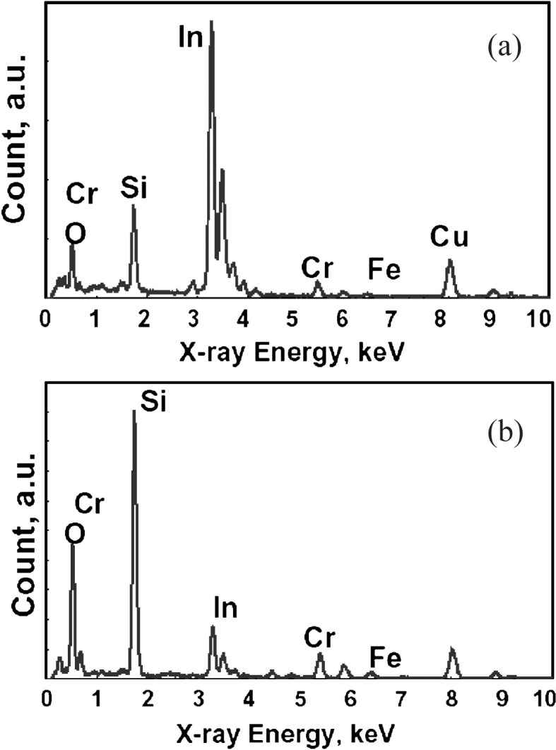
The EDX spectrum (a) of a nano-particle shown by Figs. 38(a) and (b) of matrix shown by Fig. 38(b).71)
By considering the observed micro structure and chemical elements in the tribo-layer, it is supposed that nano-particles of In dispersed in the layer may continuously supply In to the contact interface by a small amount from the inside of layer to form very thin lubricous In-based layer which is undetectable in Fig. 36 (a2). The tribo-layer of about 400 nm thickness may also act as a good suspension between the lubricous layer and hard substrate of Si3N4.
It is worth to remind that the importance of tribo-layer formed by tribo-assisted coating of In between the surface of Si3N4 pin and SUS440C disk is analogous to the tribo-layers formed on the sliding surfaces of SiC and Si3N4 in water and those on Si3N4 and CNx in N2 gas.
4. Wear
4.1. Generation of wear and formation of tribo-layer
Wear of solids takes place at any contact surfaces in friction by generating wear particles and tribo-layers accompanied by the change of microscopic morphology of surfaces in contact. It has been observed in bearings as “running-in” in the condition of boundary lubrication with liquid such as oil or water, where state of wear transits from severe to mild in repeated friction cycle and finally good conforming between contact surfaces is achieved to generate elasto-hydrodynamic and hydrodynamic lubrication. Similar mild wear state is generated on purpose in polishing for having mirror surface.
In other various contacts, wear has been recognized by “the increase in friction, vibration or leakage”, where the optimum surface roughness and profile are changed unfavorably by wear of various modes in repeated friction cycle.
In observations such as Figs. 23, 24, 30 and 37, wear is recognized as the necessary process to have good conforming between sliding surfaces and form protective and lubricious thin tribo-layer by transfer, retransfer and mechanical mixing of surface materials in the process of repeated friction cycle.
Essential parts of our observations of wear to understand those phenomena are described below.
4.2. Wear modes, wear maps and wear models of materials
4.2.1. Metallic materials
Recognition of wear modes of adhesive, abrasive, flow, fatigue, corrosive and melt shown in Fig. 4072) has been well made for metals by observations in the past 50 years.
Fig. 40.

Schematic wear modes.72) (a) Adhesive wear by adhesive shear and transfer (b) Abrasive wear by micro-cutting of ductile bulk surface (c) Flow wear by accumulated plastic shear flow (d) Fatigue wear by crack initiation and propagation (e) Corrosive wear by shear fracture of ductile tribofilm (f) Corrosive wear by shaving of soft tribofilm (g) Corrosive wear by accumulation of plastic shear flow in tribofilm (h) Corrosive wear by brittle fracture or fatigue of tribofilm (i) Melt wear by local melting and transfer or scattering.
The abrasive wear mode in Fig. 40(b) is described more in detail by the abrasive wear mode diagram, so called “wear map”, in Fig. 41(b)73) where the degree of penetration Dp, representative plastic strain εr and relative shear strength f at the contact interface are defined as follows with a model shown in Fig. 41(c);
| [4.1] |
| [4.2] |
| [4.3] |
where W: load, R: pin tip radius, H: hardness, h: indentation depth, a: contact radius, α: constant 0.17∼0.19, si: shear strength at the contact interface, k: critical shear strength of wear material.
Fig. 41.

SEM images (a) of abrasive three wear modes and abrasive wear map (b) of ductile materials described by an abrasive model (c) of a spherical hard pin on a relatively soft flat.75)
The wear map tells that the typical abrasive wear mode is fully generated only when Dp value is above 0.3. The intermediate state of wedge forming is observed when f value is larger than about 0.5 and is sensitive to the change of f value in the range of f = 0.5∼1.0.
A theoretical model is made to predict wear rate in the modes of typical abrasive and wedge forming wear and the result of theoretical calculation is shown in Fig. 4274) as a relation between wear resistance and hardness, where wear resistance is an inverse of wear rate (mm3/Nm). The plots of experimental values well agree with the theoretical prediction shown by the solid line.
Fig. 42.

Theoretical and experimental values of wear resistance (inverse of wear rate) in relation to hardness.74)
Wear in the mode of ploughing in Fig. 41(b) does not generate wear debris by one pass of sliding but cause surface plastic flow with multi-passes of mating pin by the mechanism of low cycle fatigue in the surface layer.75)
Figures 43(a), (b) and (c) show the surface extraction caused by plastic flow of surface layer around the Vickers indentation mark by the repeated sliding pass of mating steel ball surface in alkyl naphthalene. In Fig. 43(c), the initial indentation mark is well covered by the surface extraction after sliding passes of 4.8 × 10⁴. The amount of plastic flow ΔDx is measured on the indentation mark in the direction of sliding and is shown in Fig. 44 as a function of number of passes.
Fig. 43.

Surface extraction by plastic flow generated at the periphery of Vickers indentation mark on 0.45 wt% steel flat by the repeated sliding pass of bearing steel flat under the contact pressure of 9.8 MPa in alkyl naphthalene.77)
Fig. 44.
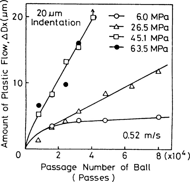
The amount of plastic flow ΔDx in the direction of sliding on the surface of 0.45 wt% carbon steel caused by the repeated sliding pass of bearing steel flat in alkyl naphthalene oil with different contact pressures of 6.0, 26.5, 45.1 and 63.5 MPa at sliding velocity of 0.52 m/s.75)
The observed flow rate is changed sensitively in the range from 0.07 to 4.46 Å/pass by the change of contact pressure and sliding velocity as shown in Figs. 45(a) and (b).75) Thin filmy wear particles generated in this way are shown in Fig. 46.76)
Fig. 45.

The effect of contact pressure (a) and sliding speed (b) on flow rate R (μm/pass) of 0.45 wt% carbon steel sliding against bearing steel flat in alkyl naphthalene at sliding velocity of 0.52 m/s. Rx: flow rate in sliding direction, Ry: flow rate in perpendicular direction to sliding.75)
Fig. 46.

SEM images of thin filmy wear particles generated by flow wear of 0.45% carbon steal.76)
The wear mode observed in Figs. 43, 44 and 45 is named as flow wear and its mechanism is considered as racheting.
Remaining question for further understanding is the microstructure and material property of surface layer. Answer would be given in the future by any model of quantum molecular dynamic simulation.
4.2.2. Ceramic materials
Ceramic bulk materials such as SiC, Si3N4, Al2O3 and ceramic coatings such as DLC (diamond-like-carbon) and CNx (carbon nitride) are generally very hard and brittle with low toughness. However they are stronger than metals in supporting load and transmitting motion when contact stress of compressive and shear are appropriately chosen.
Figure 47 describes the wear map of ceramics to show the wear regions of two wear modes of severe and mild with the newly introduced parameters of mechanical severity of contact Sc,m and thermal severity of contact Sc,t which are defined as follows;
| [4.4] |
| [4.5] |
where μ: Friction coefficient, Pmax: Hertzian contact pressure, d: Crack length, KIC: Fracture toughness, γ: Heat partition ratio, v: Sliding velocity, W: Normal load, Hv: Hardness, ΔTs: Thermal shock resistance, k: Thermal conductivity, ρ: Density, c: Specific heat.
Fig. 47.

Wear map (a) of severe and mild wear modes of ceramics, and SEM images and profiles (b) of severe and mild wear surfaces.77)
In the region of severe wear mode, surface cracks are propagated to form wear debris and wear rate becomes unacceptably high (> 10−6 mm3/Nm) for general tribo-elements.
In the region of mild wear mode, smooth wear surfaces covered by tribo-layers are formed with low wear rate (< 10−6 mm3/Nm).77)
Figure 48 describes the wear map of hard coatings sliding against a spherical pin to show three modes of delamination of coating with the newly introduced two ratios of Yf/Yb (Yield strength of coating/Yield strength of substrate) and t/a (coating thickness/contact radius).78),79)
Fig. 48.

Wear map (a) of coating delamination and SEM image (b1) of a sliding pin on Al2O3 coating, delaminated wear particles (b2) and delaminating coating (b3).78),79) t: coating thickness, a: half contact width, Y: yield strength, H: hardness, E: Young’s Modulus, μ: friction coefficient, Subscripts: f: film, s: substrate.
The map tells that crack propagation for coating delamination is initiated in the substrate, at the bonding interface or in/on the coating depending on the combination of t/a and Yf/Yb under the given elastic modulus ratio Ef /Eb and friction coefficient μ.
When the contact load is very small in the range of nN∼mN and the contact stress region is limited on the top surface of coating, the surface layer of hard ceramic coating such as silicone nitride behave like a plastic material in the repeated contact of ploughing mode shown in Fig. 41(a).
Figure 49 shows the relationship between the average amplitude of plastic strain Δεp in the contact region of CNx coating and the number of friction cycles Nc for delamination of coating surface observed in the load range of nN∼mN. The observed linear relationship on log-log scale described by
| [4.6] |
confirms the wear mechanism as low cycle fatigue.80),81) It is obvious that flow wear observed in Figs. 43∼45 and low cycle fatigue wear in Fig. 49 are wear of tribo-layers. The mild wear in Fig. 47 is also generated by forming tribo-layers on wear surfaces.
Fig. 49.

The relationship between the average amplitude of plastic strain Δεp in the contact region of CNx coating sliding against a diamond pin and the critical number of friction cycles Nc for delamination of coating surface.58),80)
4.3. Discussion on tribo-layer
It is shown and confirmed in the previous articles of water lubrication, N2-gas lubrication and tribo-coated In lubrication that the thin tribo-layer plays the key role in protecting the contact surfaces and reducing friction and wear.
Therefore its mechanical and chemical properties, microstructure and formation mechanism become main subjects to understand for better control of friction and wear.
The well recognized tribo-layer in lubrication of engine is formed on iron oxide surface by sliding against steel in lubricant of PAO (Poly-Alpha-Olefin) containing 1% ZDDP (Zinc Dialkyl Dithio Phosphate).
Figure 50 shows its cross sectional TEM image of tribo-layer of 200 nm thickness and distributions of chemical elements of Zn, Fe, P, C, O, Cr and S in it.67)
Fig. 50.

The TEM image and EDX depth profile analysis of tribo-layer formed on iron oxide in PAO containing 1% ZDDP by rubbing against steel bar.67)
It is clear from this observation that a tribo-layer is not formed by simple chemical reaction and film growth. Microscopic mechanical mixing of chemical elements and tribo-chemical reaction may take place to form a tribo-layer like one in Fig. 50. Similar discussion would be available for tribo-layers observed in Figs. 30, 37, 45 and 46 when finer analyses by TEM and EDX would be made.
5. Static friction
5.1. Junction-growth and static friction at contact of asperities
In the case of hydrodynamic lubrication, load is supported by the hydrodynamic pressure in liquid or gas film between two moving surfaces and friction is generated as the flow resistance of liquid or gas between the surfaces. In other cases of contact of solids, load is supported at micro asperity contacts which are deformed elastically and plastically under the combined effect of load and friction and are finally fractured to form wear particles.
Figure 51 shows the relationship between the friction coefficient μ and the corresponding contact area A at one plastic contact between two asperities before the occurrence of gross sliding.
Fig. 51.

Relationship between friction coefficient μ and contact area A normalized by contact area A0 at μ = 0.82),83)
Experimantal equation is given by
| [5.1] |
where A0 is the contact area at μ = 0 and α is an experimantal constant given as follows for each tested materials; α = 10.8, 8.9, 5.5 and 4.2 for mild steel, aluminum, phosphor bronze and brass respectively.82) The maximum value of μ for each material gives the so called static friction coefficient at the contact.
The theoretical curve in the figure is calculated by a plastic model and theory of slip line field.83)
It is important to know that any model for lubrication or wear should consider the change of contact area A, which is called as Junction-growth, caused by plastic deformation in contact region before gross sliding.
Static friction is observed at the last stage of the junction-growth as the termination of deformation and the separation of contact.
5.2. Contact shape effect on static friction
When friction force F is gradually increased at an elastic contact between a circle and flat under the load W in Fig. 52(a), partial micro-slips are introduced from the periphery of circular contact area by the gradual increase in F accompanied by the elastic deflection δx of circle.
Fig. 52.

Micro-slip initiation and propagation at the contact area before reaching to the observation of static friction coefficient.84)
The micro-slip region is enlarged by slip propagation caused by the further increase in F.
When all contact region is covered by the slip region, macroscopic sliding of the circle is generated and static friction coefficient μs is observed as μs = 0.85.
Figure 52(b) shows the effect of small two inclusions at the center of contact region, where micro-slips are introduced around them before the introduction along the circular periphery. Because of this mechanism, contact region is quickly covered by micro-slip giving μs = 0.69 which is much smaller than the value of μs in Fig. 52(a).
In Fig. 53, four kinds of shape of contact area of similar size are tested in the same way as in Fig. 52 to see the effect of contact shape on friction.
Fig. 53.

The effect of contact area shape on static friction coefficient μs.85)μs = 0.85 at circle, μs = 0.49 at square, μs = 0.48 at annulus, μs = 0.32 at triangle.
It is obvious in the figure that the level of coverage of micro-slip region on the contact area at the same friction force is quite different each other and the value of static friction coefficient is also very different as the result.
The observations in Figs. 52 and 53 clearly tell that the static friction coefficient in nature and engineering products strongly depends on the contact shape and micro-inclusions in the contact region.
Junction-growth at one contact between micro asperities shown in Fig. 51 can be considered as more microscopic phenomenon than micro-slip initiation and propagation in the elastic contact region.
Only when a contact element is very small in μm scale and elastic contact area is similar to the element size, junction-growth may be neglected.
6. Summary
Tribology covers the fields of friction, wear and lubrication which exist all around in nature and human society.
The demand of controlling them at high level has been increased very rapidly in the past one hundred years.
Some achievements made by the authors are described in this paper and summarized as follows;
The oil whip phenomenon is clarified theoretically for the first time in the world. Stable operation of an arbitrarily high speed rotary shaft supported by journal bearings can be made by the theory.
The dynamic anti-earthquake design method of rotary shaft-bearing systems is first proposed to avoid sudden oil whip generation by a large disturbance such as an earthquake.
Large contributions to the theoretical and experimental analyses of temperature rise and turbulence in lubricating films are also made.
The high potential of water lubrication of ceramics for practical use is shown experimentally, and main part of lubrication mechanism is made clear.
The low friction phenomena at the contact between silicon nitride/carbon nitride and carbon nitride/carbon nitride in N2 gas atmosphere are shown experimentally for the first time in the world. It promises a new lubrication method with nitrogen gas by forming lubricous tribo-layer.
Tribo-coating of indium supplied for one ∼ two minutes on a SUS440C stainless disk sliding against a silicon nitride pin in high vacuum gives low friction coefficient around 0.02 and long life over ten thousand cycles. Thin tribo-layer of the thickness around 400 nm is confirmed to play a key role for the reduction of friction and wear.
Wear maps are proposed for classifying various wear modes and the importance of tribo-layer formation is shown. The mechanisms of junction-growth at the plastic contact of asperities and micro-slip propagation at the elastic contact area are shown experimentally and theoretically to understand static friction.
Biographies
Profile
Yukio Hori was born in 1927 and graduated from the University of Tokyo in 1951. He was Lecturer 1953–, Associate Professor 1955– and then Professor of Mechanical Engineering 1965–88 at the same university. After serving for Japan Society for the Promotion of Science 1988–94, he has been active at Kanazawa Institute of Technology.
He performed pioneering work on the stability of a rotary shaft supported by oil film bearings, especially on oil whip or self-excited vibrations of the shaft. Oil whip had been barriers to increase in speed of rotary machines or growth of output of rotary machines such as electric generators for many years. These barriers were first lifted by Hori’s oil whip theory. He published since then many papers related to oil whip. Among others, he first discussed the possibility of oil whip being triggered by earthquake.
He also made important contributions to theoretical and experimental analyses of temperature rise and turbulence in fluid films in high speed bearings and seals.
Although not included in this paper, his work also covers a variety of fields such as rheology of molten high-polymers and mechanical properties of solid high-polymers.
He was awarded a Medal of Purple Ribbon in 1993 and the Japan Academy Prize in 2007.

Profile
Koji Kato was born in 1943 and graduated from Tohoku University in 1966. He received Degree of Doctor in 1974 from the same university at the Department of Mechanical Engineering.
He was promoted to professor in the same department in 1978 and worked there as head of Tribology Laboratory until his retirement on 31 March 2007. He has been professor at Nihon University and professor emeritus of Tohoku University since April 2007.
His research field has been fundamentals and applications of tribology where he wrote more than 300 reviewed papers on international journals and co-authored 14 books published by international publishers. He gave 68 invited lectures at international conferences on tribology, ceramics, coatings, materials, machineries etc. in 26 countries and he has been editorial board for 7 international journals of tribology.
He received 4 best paper awards from 3 Japanese and 1 American academic journals of societies. He received Haute Distinction Honoris Causa from Ecole Centrale de Lyon (France), International Award from Society of Tribologists and Lubrication Engineers (USA), Jacob Wallenberg Award from Royal Swedish Academy of Engineering Sciences, Mayo D. Hersey Award from American Society of Mechanical Engineers, the Japan Academy Prize from the Japan Academy, Tribology Gold Medal from Tribology Trust (UK) and is Foreign Member of Royal Swedish Academy of Engineering Sciences.

References
- 1).Hori, Y. (1959) A theory of oil whip. Trans. ASME, Ser. E, J. Appl. Mech. 26, 189–198 [Google Scholar]
- 2).Hori, Y. (1958) Oil whip. J. JSME 61, 1348–1356 (in Japanese). [Google Scholar]
- 3).Hori, Y., Hasuike, A., Higashi, T. and Nagase, Y. (1975) A study on foil bearings —An application to tape memory devices—. Proc. of 1975 Joint ASME-JSME Applied Mechanics Western Conference, Honolulu, Hawaii, March 24–27, pp. 121–125 #D-5. Bull. JSME 20–141 (1977-3) pp. 381–387 [Google Scholar]
- 4).Hori, Y., Kato, T. and Narumiya, H. (1981) Rubber surface squeeze film. Trans. ASME, J. Lubrication Tech. 103, 398–405 [Google Scholar]
- 5).Kim, K.W., Tanaka, M. and Hori, Y. (1983) A three-dimensional analysis of thermohydrodynamic performance of sector-shaped, tilting-pad thrust bearings. Trans. ASME, J. Lubrication Tech. 105, 406–413 [Google Scholar]
- 6).Mitsui, J., Hori, Y. and Tanaka, M. (1986) An experimental investigation on the temperature distribution in circular journal bearings. Trans. ASME, J. Lubrication Tech. 108, 621–627 [Google Scholar]
- 7).Kato, T. and Hori, Y. (1983) Turbulent lubrication theory using k–ε Model for journal bearings. J. Japan Soc. Lubrication Eng. 28, 907–914 (in Japanese). [Google Scholar]
- 8).Hori, Y. (2006) Hydrodynamic Lubrication. Springer-Verlag [Google Scholar]
- 9).Newkirk, B.L. and Taylor, H.D. (1925) Shaft whipping due to oil action in journal bearings. General Electric Review, 559–568 [Google Scholar]
- 10).Newkirk, B.L. and Lewis, J.F. (1956) Oil film whirl — An investigation of disturbances due to oil films in journal bearings. Trans. ASME 78, 21–27 [Google Scholar]
- 11).Newkirk, B.L. (1956) Varieties of shaft disturbances due to fluid films in journal bearings. Trans. ASME 78, 985–988 [Google Scholar]
- 12).Pinkus, O. (1956) Experimental investigation of resonant whip. Trans. ASME 78, 975–983 [Google Scholar]
- 13).Robertson, D. (1933) Whirling of a journal in a sleeve bearing. Phil. Mag. Ser. 7 15, 113–130 [Google Scholar]
- 14).Poritsky, H. (1953) A contribution to the theory of oil whip. Trans. ASME 75, 1153–1161 [Google Scholar]
- 15).Hori, Y. (1955) A theory of oil-whip in journal bearings. Proc. of the 5th Japan National Congress for Applied Mechanics, Sept. 1955, pp. 395–398 [Google Scholar]
- 16).Hori, Y. (1959) Study on oil whip. Dissertation, University of Tokyo (in Japanese).
- 17).Someya, T. (1963) Stabilität einer in zylindrischen Gleitlagern laufenden, unwuchtfreien Welle. Ingenieur-Archiv 33 Band, 2. Heft, 85–108 [Google Scholar]
- 18).Someya, T. (1964) Stability of a balanced shaft running in cylindrical journal bearings. Proc. Lubrication and Wear Second Convention, IMechE, London, paper 21, pp. 1–21
- 19).Someya, T. (1965) Schwingungs- und Stabilitäts-verhalten einer in zylindrischen Gleitlagern laufenden Welle mit Unwucht. VDI–Forschungsheft 510, 1–36 [Google Scholar]
- 20).Gotoda, H. (1963) Research on the vibration of a rotating shaft supported by journal bearings. Report of the Research Subcommittee on Radial Gasturbines, no. 4, JSME, pp. 114–206, Appendix pp. 207–244 (in Japanese).
- 21).Gotoda, H. (1964) On the vibration of a rotating shaft supported by journal bearings (first report, unbalance vibration. Trans. JSME 30, 887–900 (in Japanese). [Google Scholar]
- 22).Funakawa, M. and Tatara, A. (1964) Stability criterion of an elastic rotor in journal bearings. Trans. JSME 30, 1238–1244 (in Japanese). [Google Scholar]
- 23).Nakagawa, E. and Aoki, H. (1965) Approximate solution for elastic and damping properties of oil film in journal bearings. Trans. JSME 31, 1398–1408 (in Japanese). [Google Scholar]
- 24).Harada, M. and Aoki, H. (1971) The dynamic characteristics of fully circular journal bearings in the turbulent region. J. Japan Soc. Lubrication Eng. 16, 429–436 (in Japanese). [Google Scholar]
- 25).Hori, Y. (2003) Compilation of Manufacturers’ Data.
- 26).Holmes, A.G., Ettles, C.M.McC. and Mayes, I.W. (1978) The dynamics of multi-rotor systems supported on oil film bearings. Trans. ASME, Ser. L, 100, 156–164 [Google Scholar]
- 27).Kikuchi, K., Takagi, M. and Kobayashi, S. (1979) Effect of alignment on vibration of multi-bearing rotor system (First report, vibration characteristics of three-bearing, one-rotor system). Trans. JSME 45, 1349–1356 (in Japanese). [Google Scholar]
- 28).Uematsu, R. and Hori, Y. (1980) Influence of misalignment of support journal bearings on stability of a multi-rotor system. Tribology International. 13, 249–252 [Google Scholar]
- 29).Nasuda, T. and Hori, Y. (1982) Influence of misalignment of support journal bearings on stability of multi-rotor systems. Proc. IFToMM Int. Conf. on Rotordynamic Problem in Power Plants, Rome, Sept. 1982, pp. 389–395 [Google Scholar]
- 30).Falkenhagen, G.L., Gunter, E.J. and Schuller, F.T. (1972) Stability and transient motion of a vertical three-lobe bearing system. J. Eng. Industry, Trans. ASME 94, 665–667 [Google Scholar]
- 31).Allaire, P.E. and Flack, R.D. (1980) Journal bearing design for high speed turbomachinery. InBearing Design — Historical Aspects, Present Technology and Future Problems (ed. Anderson, W.J.). ASME Publication [Google Scholar]
- 32).Li, D.F., Choy, K.C. and Allaire, P.E. (1980) Stability and transient characteristics of four multilobe journal bearing configurations. J. Luburication Tech., Trans. ASME 102, 291–299 [Google Scholar]
- 33).Hashimoto, H., Wada, S. and Tsunoda, H. (1984) Performance characteristics of elliptical journal bearings in turbulent flow regime. Bull. Japan Soc. Mech. Eng. 27–232, 2265–2271 [Google Scholar]
- 34).Tatara, A. (1969) An experimental study on the stabilizing effect of floating bush journal bearings. J. JSME 72, 1564–1569 (in Japanese). [Google Scholar]
- 35).Tanaka, M. and Hori, Y. (1972) Stability characteristics of floating bush bearings. Trans. ASME, Ser. F 94, 248–259 [Google Scholar]
- 36).Lund, J.W. (1964) Spring and damping coefficients for the tilting pad journal bearing. ASLE Trans. 7, 342–352 [Google Scholar]
- 37).Orcutt, F.K. (1967) The steady-state and dynamic characteristics of the tilting-pad journal bearing in laminar and turbulent flow regimes. Trans. ASME, J. Lub. Tech. 89, 392–404 [Google Scholar]
- 38).Iida, S. (1974) A study on the vibration characteristics of tilting pad journal bearings. Trans. JSME 40, 875–884 (in Japanese). [Google Scholar]
- 39).Hashimoto, H., Wada, S. and Marukawa, T. (1985) Performance characteristics of large scale tilting-pad journal bearings. Bull. Japan Soc. Mech. Eng. 28–242, 1761–1768 [Google Scholar]
- 40).Hori, Y. (1988) Anti-earthquake considerations in rotordynamics. Proc. 4th IMechE International Conference on Vibrations in Rotating Machinery, Edinburgh, Sept. 1988, pp. 1–8 [Google Scholar]
- 41).Hori, Y. and Kato, T. (1989) Seismic effect on the stability of a rotor supported by oil film bearings. Trans. JSME, C 55, 611–617 (in Japanese). [Google Scholar]
- 42).Hori, Y. and Kato, T. (1990) Earthquake-induced instability of a rotor supported by oil film bearings. Trans. ASME, J. Vibration and Acoustics. 112, 160–165 [Google Scholar]
- 43).Adams, M.L., Adams, M.L. and Guo, J.-S. (1996) Simulations and experiments of the non-linear hysteresis loop for rotor-bearing instability. Proc. IMechE International Conference on Vibrations in Rotating Machinery Oxford, pp. 309–319 [Google Scholar]
- 44).Kato, T., Koguchi, K. and Hori, Y. (1991) Seismic response of a multirotor system supported by oil film bearings. Trans. JSME, C 57, 3761–3768 (in Japanese). [Google Scholar]
- 45).Kato, T., Matsuoka, H. and Hori, Y. (1992) Seismic response of a multirotor system supported by oil film bearing (Effect of misalignment). Trans. JSME, C 58, 1572–1578 (in Japanese). [Google Scholar]
- 46).Kato, T., Koguchi, K. and Hori, Y. (1992) Seismic response of a linearly stable multirotor system. Proc. IMechE International Conference on Vibrations in Rotating Machinery, Bath, June, 1992, pp. 7–11 [Google Scholar]
- 47).Kato, T., Matsuoka, H. and Hori, Y. (1993) Seismic response of a linearly stable, misaligned multi-rotor system. Tribology Transaction, S.T.L.E. 36, 311–315 [Google Scholar]
- 48).Dowson, D. (1962) A generalized Reynolds equation for fluid film lubrication. Int. J. Mech. Sci. 4, 159–170 [Google Scholar]
- 49).Wilcock, D.F. (1950) Turbulence in high-speed journal bearings. Trans. ASME 72, 825–834 [Google Scholar]
- 50).Constantinescu, V.N. (1959) On turbulent lubrication. Proc. Inst. Mech. Eng. 173, 881–900 [Google Scholar]
- 51).Ng, C.-W. and Pan, C.H.T. (1965) A linearized turbulent lubrication theory. J. Basic Eng., Trans. ASME, Ser. D 87, 675–688 [Google Scholar]
- 52).Orcut, F.K. and Arwas, E.B. (1967) The steady-state and dynamic characteristics of a full circular bearing and a partial arc bearing in the laminar and turbulent flow regimes. J. Lubrication Tech., Trans. ASME, Ser. F 89, 143–153 [Google Scholar]
- 53).Elrod, H.G.Jr. and Ng, C.W. (1967) A theory of turbulent fluid films and its application to bearings. J. Lubrication Tech., Trans. ASME, Ser. F 89, 346–362 [Google Scholar]
- 54).Jones, W.P. and Launder, B.E. (1973) The calculation of low-Reynolds-number phenomena with a two-equation model of turbulence. Int. J. Heat Mass Transfer 16, 1119–1130 [Google Scholar]
- 55).Hassid, S. and Poreh, M. (1978) A turbulent energy dissipation model for flows with drag reduction. J. Fluids Eng., Trans. ASME 100, 107–112 [Google Scholar]
- 56).Kato, K. (2001) Water lubrication of ceramics. Proc. of 2nd World Achievements Tribology Conference, Scientific Industrial Applications Future Challenges, Vienna, pp. 51–58 [Google Scholar]
- 57).Lebeck, A.O. (1987) Parallel sliding load support in the mixed friction regime Part1 — The experimental data. J. Tribology, ASME 109-1, 189–195 [Google Scholar]
- 58).Wang, X., Kato, K., Adachi, K. and Aizawa, K. (2003) Loads carrying map for the surface texture design of SiC thrust bearing sliding in water. Tribology International 36, 189–197 [Google Scholar]
- 59).Adachi, K., Otsuka, K., Wang, X. and Kato, K. (2006) Effects of surface texture on water lubrication properties of advanced ceramics. J. Japan Soc. Abrasive Tech. 50, 107–110 [Google Scholar]
- 60).Chen, M., Kato, K. and Adachi, K. (2001) The difference in running-in period and friction coefficient between self mated Si3N4 and SiC under water lubrication. Tribology Letters 11, 23–28 [Google Scholar]
- 61).Chen, M., Adachi, K. and Kato, K. (2001) Friction and wear of selfmated SiC and Si3N4 sliding in water. Wear 250, 246–255 [Google Scholar]
- 62).Xu, J. and Kato, K. (2000) Formation of tribo-chemical layer of ceramics sliding in water and its role for low friction. Wear 245, 61–75 [Google Scholar]
- 63).Umehara, N., Endo, H. and Kato, K. (2001) Water lubrication mechanism in sliding of SiC on itself. Proc. of the International Tribology Conference Nagasaki, 20002, pp. 863–868 [Google Scholar]
- 64).Umehara, N., Tatsuno, M. and Kato, K. (2001) Nitrogen lubricated sliding between CNx coatings and ceramic balls. Proc. of the International Tribology Conference Nagasaki, 20002, pp. 1007–1012 [Google Scholar]
- 65).Kato, K., Umehara, N. and Adachi, K. (2003) Friction, wear and N2 — lubrication of carbon nitride coatings: A review. Wear 254, 1062–1069 [Google Scholar]
- 66).Adachi, K., Wakabayashi, T. and Kato, K. (2005) The effect of sliding history on the steady state friction coefficient between CNxcoating under N2lubrication. Proc. of the 31st Leeds-Lyon Symposium on Tribology, 2004, Leeds, UK, Tribology and Interface Engineering Series, 48 (eds. Dowson, D.et al. ), Elsevier, pp. 673–677 [Google Scholar]
- 67).Ito, K., Martin, J.M., Minfray, C. and Kato, K. (2007) Formation mechanism of a low friction ZDDP tribofilm on iron oxide. STLE Transactions 50, 1–6 [Google Scholar]
- 68).Ito, K., Martin, J.M., Minfray, C. and Kato, K. (2006) Low friction tribofilm formed by the reaction of ZDDP on iron oxide. Tribology International 39, 1538–1544 [Google Scholar]
- 69).Kato, K., Furuyama, H. and Mizumoto, M. (1990) The fundamental properties of tribo-coating films in ultra high vacuum. Proc. of the Japan International Tribology Conference Nagoya, 19901, pp. 261–266 [Google Scholar]
- 70).Adachi, K. and Kato, K. (2000) Reliable design of space system in tribology viewpoint. Proc. of the 22nd International Symposium on Space Technology and Science 1, 593–598 [Google Scholar]
- 71).Adachi, K. and Kato, K. (2008) In-situ and On-demand Lubrication by Tribo-coating for Space Applications. J. Eng. Tribology, IMechE (to be published). [Google Scholar]
- 72).Kato, K. (2002) Classification of wear mechanisms/ models. Proc. Inst. Mech. Eng. Part J, J. Eng. Tribology 216, 349–355 [Google Scholar]
- 73).Kato, K. and Hokkirigawa, K. (1985) Abrasive wear diagram. Proc. of Eurotrib ’85 — International Congress on Tribology 4, 1–5 [Google Scholar]
- 74).Hokkirigawa, K. and Kato, K. (1989) Theoretical estimation of abrasive wear resistance based on microscopic wear mechanism. Wear of Materials, ASME, 1–8
- 75).Akagaki, T. and Kato, K. (1988) Simulation of flow wear in boundary lubrication using a Vickers indentation method. STLE Tribology Transactions 31, 311–316 [Google Scholar]
- 76).Akagaki, T. and Kato, K. (1987) Plastic flow process of surface layers in flow wear under boundary lubricated conditions. Wear 117, 179–196 [Google Scholar]
- 77).Adachi, K., Kato, K. and Chen, N. (1997) Wear map of ceramics. Wear 203–204, 291–301 [Google Scholar]
- 78).Diao, D.F., Kato, K. and Hayashi, K. (1992) The local yield map of hard coating under sliding contact. Thin films in tribology. Proc. of the 19th Leeds-Lyon Symposium on Tribology, Leeds, UK, 1991, Tribology Series 25 (eds. Dowson, D.et al. ), Elsevier, pp. 419–427 [Google Scholar]
- 79).Kato, K. (1995) Microwear mechanisms of coatings. Surface and Coating Technology 76–77, 469–474 [Google Scholar]
- 80).Kato, K., Koide, H. and Umehara, N. (1998) Microwear mechanisms of thin hard coatings sliding against diamond tip of AFM. Adv. Info. Storage Sys., 289–302 [Google Scholar]
- 81).Wang, D. F. and Kato, K. (2003) Nano-scale fatigue wear of carbon nitride coating: Part II — Wear Properties. Trans. ASME, J. Tribology 125, 430–436 [Google Scholar]
- 82).Kayaba, T. and Kato, K. (1978) Experimental analysis of junction growth with a junction model. Wear 51, 105–116 [Google Scholar]
- 83).Kayaba, T. and Kato, K. (1978) Theoretical analysis of junction growth. The Technology Reports of the Tohoku University 43–1, 1–10 [Google Scholar]
- 84).Liu, J., Oba, K., Kato, K. and Inooka, H. (1995) Partial slip visualization at contact surface with the correlation method. J. Visual. Soc. Japan 15, 47–53 (in Japanese). [Google Scholar]
- 85).Adachi, K., Kato, K., Liu, J. and Kawamura, H. (2004) The effect of contact morphology on initiation and propagation of micro-slip at contact interface. Proc. of the ASME/STLE International Joint Tribology Conference, TRIB2004-64389.