Abstract
We present and demonstrate an approach for femtosecond laser processing by using patterned vector optical fields (PVOFs) composed of multiple individual vector optical fields. The PVOFs can be flexibly engineered due to the diversity of individual vector optical fields in spatial arrangement and distribution of states of polarization, and it is easily created with the aid of a spatial light modulator. The focused PVOFs will certainly result in various interference patterns, which are then used to fabricate multi-microholes with various patterns on silicon. The present approach can be expanded to fabricate three-dimensional microstructures based on two-photon polymerization.
On account of the growing interest in laser micromachining in insulators, semiconductors and metals1,2,3 for applications in nanoelectronic, microreactors and microdevices, ultrashort pulsed laser ablation offers a superior means due to the minimization of the thermal effects and collateral damage4. To improve the micromachining efficiency, multi-beam interference has been used to fabricate multi-microholes5,6,7, two- and three-dimensional microstructures8,9,10,11. However, this multi-beam interference is less flexible and all the beams are still scalar fields which have spatially homogeneous distribution of polarization.
Polarization, as an intrinsic and fundamental nature of light, plays a crucial role in various aspects. The states of polarization (SoPs) have been successfully used to manipulate optical fields. For instance, vector optical fields12,13,14 as a kind of novel optical fields, which have spatially inhomogeneous SoP distribution, have attracted more and more attentions due to the novel properties14,15. As is well known, the field collapse and the multiple filamentation have a common feature, which is its randomness, because they are initialed by the axial symmetry breaking caused by random noise. The axial symmetry breaking of optical field by engineering the spatial SoP structure has been demonstrated to be an extremely effective method for realizing the designable, controllable and robust field collapse and filamentation in nonlinear Kerr medium16. The vector optical fields have been confirmed to fabricate microstructures17,18,19.
In this paper, we present an approach for fabricating the multi-microholes, by using femtosecond (fs) patterned vector optical field (PVOF) composed of multiple vector optical fields. Inasmuch as the multiple vector optical fields could have arbitrary spatial arrangement and any individual vector optical field could also have arbitrary spatial SoP distribution, such two degrees of freedom make the PVOF have the diversity. Consequently, the resultant diversity of the focal field patterns of the focused PVOFs is possible to fabricate various multi-microhole patterns.
Results
Principle
The fs PVOFs for fabricating multi-microholes are more flexible and efficient with respect to the fs single optical filed and even the fs multiple optical fields, because the fs PVOFs have more controllable degrees of freedom, such as the spatial arrangement and number of individual vector optical fields as well as the shape and the SoP distribution of each individual vector optical field. Here we focus on the cases only when the individual vector optical fields which form the PVOF are the azimuthally-variant linearly-polarized vector fields (AV-LP-VFs) and have the same radius of a. The generated PVOF is located at the front plane of a focal lens L with a focal length of f. The front and rear focal planes of L are defined as the planes P and F, respectively. Two Cartesian coordinate systems (x, y) and (x′, y′) as well as the corresponding polar coordinate systems (r, ϕ) and (r′, ϕ′) attach on the planes P and F, respectively.
An AV-LP-VF  with a topological charge m and an initial phase ϕ0, which locates at the origin (0, 0) in the plane P, can be written in Jones Matrix as13,20,21,22
 |
Under the paraxial condition, when  is focused, its SoPs are not changed. Based on the Huygens-Fresnel principle, its focal field
  is written in the plane F as
 |
with
where p = 2πar′/λf, λ is the wavelength of laser, a is the radius of  , A′0 is a constant, and 1F2 [ ] is the generalized hypergeometric function, respectively. Thus the intensity distribution of the focal field
  should be
We can find from Eq. (2b) that due to  , for the AV-LP-VF with the topological charge m and the initial phase ϕ0, its focal intensity
  depends on m only independent of ϕ0, i.e.,
For two special cases of m = 0 and 1,  degenerates into the linearly-polarized scalar field and the 1st-order AV-LP-VF, respectively. Thus Eqs. (2) are simplified into
 |
with
and
 |
with
Here Jn ( ) and Hn ( ) are the nth-order Bessel and Hankel functions of the first kind, respectively.
We focus on the case that the PVOF E is composed of N individual AV-LP-VFs, which have the same m while the different ϕj0. When the center of the jth AV-LP-VF is located at (xj0, yj0) (j = 1, …, N), E can be represented in the plane P as
 |
where  and δ ( ) are the convolution operator and the well-known δ function, respectively.
  is easily given from
  in Eq. (1), provided that ϕ0 is replaced by ϕj0 only.
Thus the focal field E′ of the PVOF E can be written in the plane F as
where Pj is the propagation factor of the jth AV-LP-VF
and  is easily obtained from
  in Eq. 2(b), provided that ϕ0 is replaced by ϕj0 only.
Finally, the intensity distribution of the focused PVOF should be written as
with the interference factor
 |
Clearly, the interference factor P depends in general on the SoPs (which is described by  ) and the propagation factors Pj of all the N individual AV-LP-VFs. If all the AV-LP-VFs are identical, however, P depends only on Pj due to
  and
and  . Thus the interference factor P in Eq. (8) degenerates into
 |
The above Eq. (8) implies that the intensity  of the focused PVOF is determined by the modulated
  by the interference factor P of the N individual AV-LP-VFs, where
  is the intensity of the focused individual AV-LP-VF.
Experiments
The experimental schematic for fabricating the multi-microholes is very similar to that used in Ref. 18. The unique difference is that the single vector optical field in Ref. 18 is replaced by the PVOF. To generate the PVOF, the fs pulses are from a Ti:sapphire regenerative amplifier, which has a fundamental Gaussian mode, a central wavelength of 806 nm, a pulse duration of 35 fs, and a repetition rate of 1 kHz. Two achromatic 1/2 wave plates and a Glan prism between them are used to control the energy and the polarization direction of the fs pulses. After passing through an electromechanical shutter controlling the pulse shots for punching on the sample, the fs pulsed laser is expanded by a pair of lenses and then is incident into a vector optical field generation system. In this system, except for the hologram displayed at a spatial light modulator is a patterned hologram composed of multiple holographic gratings instead of a single holographic grating in Refs. 13,20,21,22 others are the same as Refs. 13,20,21,22. Any individual AV-LP-VF of the generated PVOF has the near flat-top intensity distribution. However, the individual AV-LP-VFs are allowed to have the different SoP distributions. The pulse duration of the generated fs PVOF is broadened to ~70 fs. Finally, the generated PVOF is focused by an achromatic focusing lens L with a focal length of f = 50 mm and a numerical aperture of 0.15 and then is normally incident onto the polished p-type single-crystalline Si (100) wafer with an impurity level of 1016–1017 cm−3. The ablated silicon sample was soaked in hydrofluoric acid with concentration of 4% for 10 minutes and then is sonic cleaned in deionized water for 10 minutes. The surface morphologies of the ablated samples are observed by a scanning electron microscopy.
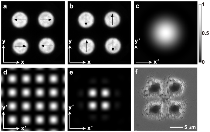
We now experimentally investigate the fabrication of multi-microholes on silicon surface, by using the focused fs PVOFs. In experiments, we focus on the cases only when all the individual vector optical fields forming the PVOF are the AV-LP-VFs with the same topological charge m and the same radius of a. We first explore a special PVOF composed of four individual linearly-polarized scalar fields (corresponding to the m = 0 AV-PL-VF). The experimentally generated two kinds of PVOFs composed of four individual linearly-polarized scalar fields with a = 1.0 mm. The four individual fields form a square and locate at (x10, y10) = (1.56, 1.56) mm, (x20, y20) = (−1.56, 1.56) mm, (x30, y30) = (−1.56, −1.56) mm, and (x40, y40) = (1.56, −1.56) mm, respectively, as shown in Figs. 1a and 1b. The two individual fields in the first and third quadrants have the same initial phases ϕ10 = ϕ30 = 0 in Fig. 1a (ϕ10 = ϕ30 = π/2 in Fig. 1b), while the two in the second and fourth quadrants also have the same initial phases ϕ20 = ϕ40 = π in Fig. 1a (ϕ20 = ϕ40 = 3π/2 in Fig. 1b), respectively. The arrows in the individual fields in Figs. 1a and 1b show the corresponding SoPs. The simulation results reveal a fact that for any one of the individual fields (Figs. 1a and 1b), its focal field has the same intensity pattern of an Airy spot (Fig. 1c), as the above theoretical predication, implying that the initial phase determining SoP has no influence on the focal intensity pattern. The simulated interference pattern described by the interference factor P exhibits a tetragonal lattice (Fig. 1d). As shown in Eq. (6b), the interference pattern depends on both positions and SoPs of the four individual fields. The simulated intensity pattern of the focused PVOF is composed of four bright spots exhibiting a square (Fig. 1e), which originates from the splitting of the Airy spot of the focused individual field due to the modulation of the interference factor of the four fields. At a fluence of about 6.9 J/cm2, four microholes are punched on the silicon surface by 50 pulses (Fig. 1f), which has the same pattern as the focused PVOF (Fig. 1e).
Figure 1. Fabrication of multi-microholes by the fs PVOFs composed of four individual linearly-polarized scalar fields with m = 0 and a = 1.0 mm.
(a) and (b) are the two PVOFs composed of four individual linearly-polarized scalar fields, which arrange a square, where the arrows show the SoP configurations. (c) shows the simulated Airy spot of the focused individual field. (d) is the simulated interference pattern with a tetragonal lattice of four individual fields. (e) indicates the simulated pattern of the focused PVOF, which contains four bright spots. (c)–(e) have a dimension of 60 × 60 μm2. (f) is the SEM image of the multi-microholes fabricated by 50 pulses at a fluence of about 6.9 J/cm2.
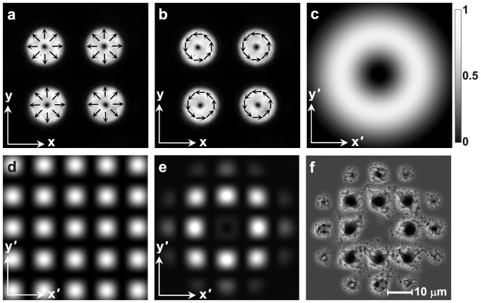
Differently from the case in Fig. 1, we now explore experimentally the fabrication of multi-microholes by the PVOFs composed of four identical AV-LP-VFs with m = 1 and a = 1.0 (Fig. 2). As shown in Figs. 2a and 2b, four radially-polarized (ϕj0 = 0, where j = 1 ~ 4) and four azimuthally-polarized (ϕj0 = π/2) fields have the same arrangement as Figs. 1a and 1b, respectively. The simulation results and the above theory reveal a fact that the m = 1 AV-LP-VF for any ϕ0 is always focused into the same focal ring (Fig. 2c) instead of the Airy spot. The simulated interference pattern described by the interference factor P also exhibits a tetragonal lattice (Fig. 2d). It should be pointed out that the patterns in Figs. 1d and 2d exhibit both the same tetragonal lattice and the same lattice period, but both exist a shift with a 1/2 lattice period in the x′ and y′ directions. The simulated intensity pattern of the focused PVOFs in Figs. 2a and 2b contains eight bright spots forming a square (Fig. 2e), which originates from the splitting of the focal ring due to the modulation of the interference factor of the four individual AV-LP-VFs. At a fluence of about 6.9 J/cm2, eight microholes are punched on the silicon surface by 50 pulses (Fig. 2f), like the focal intensity pattern (Fig. 2e).
Figure 2. Fabrication of multi-microholes by the fs PVOF composed of four identical AV-LP-VFs with m = 1 and a = 1.0 mm.
(a) and (b) are the two generated PVOFs composed of four identical radially-polarized and azimuthally-polarized fields, respectively, which arrange a square, where the arrows show the SoP configurations. (c) shows the simulated focal ring of the focused individual AV-LP-VF. (d) is the simulated interference pattern with a tetragonal lattice of four individual fields. (e) indicates the simulated pattern of the focused PVOF, which contains eight bright spots. (c)–(e) have a dimension of 60 × 60 μm2. (f) is the SEM image of the multi-microholes fabricated by 50 pulses at a fluence of about 6.9 J/cm2.
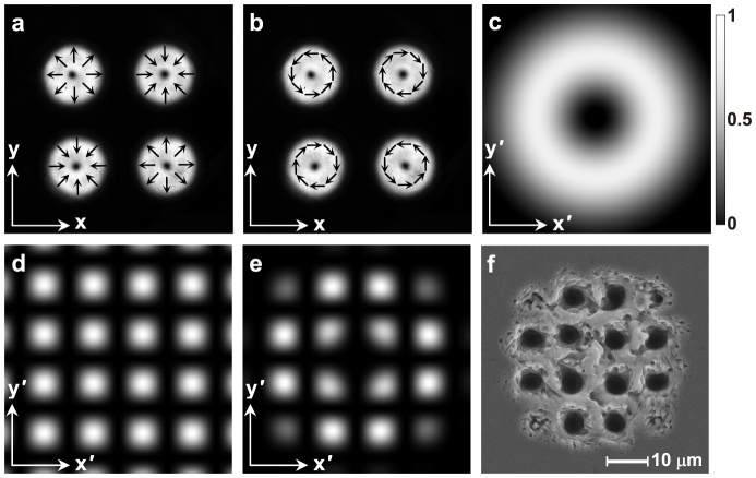
Figure 3 shows the other case similar to Fig. 2. Compared Fig. 3a with Fig. 2a and Fig. 3b with Fig. 2b, ϕ10 = ϕ30 = 0 in Fig. 2a are changed into ϕ10 = ϕ30 = π in Fig. 3a and ϕ10 = ϕ30 = π/2 in Fig. 2b are changed into ϕ10 = ϕ30 = 3π/2 in Fig. 3b, respectively. Any individual vector field in Figs. 3a and 3b can also be focused into a focal ring in Fig. 3c that is the same as Fig. 2c. The simulated interference pattern described by P of four individual vector fields in Fig. 3a or 3b exhibits also a tetragonal lattice in Fig. 3d, which is the same as Fig. 1d while has a shift of 1/2 lattice period in the x′ and y′ directions. As shown in Fig. 3e, however, the simulated intensity pattern of the focused PVOFs in Figs. 3a and 3b is composed of twelve intense spots exhibiting a “Cross” shape. At a fluence of about 6.9 J/cm2, Fig. 3f shows the fabricated microholes on the silicon surface by 50 pulses.
Figure 3. Fabrication of multi-microholes by the fs PVOF composed of four AV-LP-VFs with m = 1 and a = 1.0 mm.
(a) and (b) are two generated PVOFs composed of four radially-polarized fields (with ϕ10 = ϕ30 = π and ϕ20 = ϕ40 = 0) and four azimuthal-polarized fields (with ϕ10 = ϕ30 = 3π/2 and ϕ20 = ϕ40 = π/2), respectively, which arrange a square, where the arrows show the SoP configurations. (c) shows the simulated focal ring of any individual AV-LP-VF. (d) is the simulated interference pattern with a tetragonal lattice of four individual fields. (e) indicates the simulated pattern of the focused PVOF. (c)–(e) have a dimension of 60 × 60 μm2. (f) the SEM image of the multi-microholes fabricated by 50 pulses at a fluence of about 6.9 J/cm2.
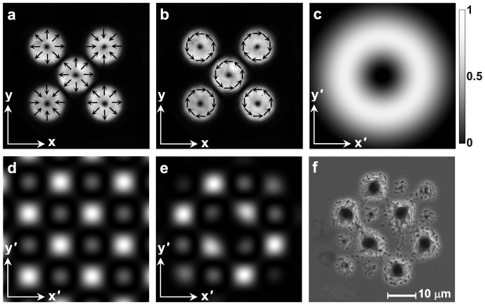
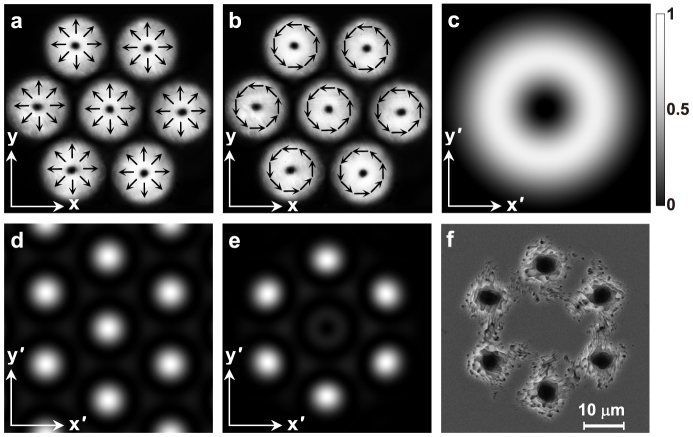
To further investigate the feature of our method, we also generate a relatively complex PVOF composed of five individual radially polarized fields, as shown in Fig. 4. For the unique difference of Fig. 4a (or Fig. 4b) with Fig. 3a (or Fig. 3b), an identical radially-polarized (or azimuthally-polarized) field is added at the center. In the simulated interference pattern of five fields, as shown in Fig. 4d, the bright spots and the dark spots form a nested lattice composed of two tetragonal lattices. The focal field in Fig. 4e exhibits a beautiful pattern composed of six intense spots. Figure 4f shows the fabricated multi-microholes at a fluence of about 6.9 J/cm2 by 50 pulses.
Figure 4. Fabrication of multi-microholes by the fs PVOF composed of five identical AV-LP-VFs with m = 1 and a = 1.0 mm, which arrange a face-centered square.
(a) and (b) are two generated PVOFs composed of five radially-polarized fields and five azimuthal-polarized fields, respectively, where the arrows show the SoP configurations. (c) shows the simulated focal ring of any individual AV-LP-VF. (d) is the simulated interference pattern of five individual fields, exhibiting a nested lattice composed of two tetragonal lattices (bright and dark spots). (e) indicates the simulated pattern of the focused PVOF. (c)–(e) have a dimension of 60 × 60 μm2. (f) is the SEM image of the multi-microholes fabricated by 50 pulses at a fluence of about 6.9 J/cm2.
Finally, the PVOF is composed of seven identical radially-polarized (or azimuthally-polarized) fields with m = 1 and ϕ10 = 0 (or ϕj0 = π/2, where j = 1, …, 7) in Fig. 5a (or Fig. 5b). The seven identical AV-LP-VFs have the same radius of a = 1.1 mm and are located at (x10, y10) = (2.270, 0) mm, (x20, y20) = (1.135, 1.966) mm, (x30, y30) = (−1.135, 1.966) mm, (x40, y40) = (−2.27, 0) mm, (x50, y50) = (−1.135, −1.966) mm, (x60, y60) = (1.135, −1.966) mm, and (x70, y70) = (0, 0), respectively. The simulated interference pattern of seven individual fields exhibits a trigonal lattice, as shown in Fig. 5d. The simulated focal field pattern in Fig. 5e is composed of six intense spots exhibiting a hexagon. At a fluence of about 6.9 J/cm2, six microholes are formed on the silicon surface for 50 pulses as shown in Fig. 5f, which is in good agreement with the intense spot pattern shown in Fig. 5e.
Figure 5. Fabrication of multi-microholes by the fs PVOF composed of seven identical AV-LP-VFs with m = 1 and a = 1.1 mm, which arrange a face-centered hexagon.
(a) and (b) are two generated PVOFs composed of seven radially-polarized fields and seven azimuthal-polarized fields, respectively, where the arrows show the SoP configurations. (c) shows the simulated focal ring of any individual AV-LP-VF. (d) is the simulated interference pattern of seven identical fields, exhibiting a trigonal lattice. (e) indicates the simulated pattern of the focused PVOF, which contains six bright spots exhibiting a hexagon. (c)–(e) have a dimension of 60 × 60 μm2. (f) is the SEM image of the multi-microholes fabricated by 50 pulses at a fluence of about 6.9 J/cm2.
Discussion
We only explore the cases of PVOFs composed of AV-LP-VFs, which have the same topological charge, the same geometric shape (circle), and the simple arrangement. In fact, many degrees of freedom can be used to generate various PVOFs and to then fabricate various microstructures, including (i) the geometric shape and size, the spatial phase and SoP distribution of each individual AV-LP-VF, (ii) the spatial arrangement and number of individual AV-LP-VFs. For any individual AV-LP-VF, its geometric shape is allowed to be arbitrary shape such as circle, square, triangle, hexagon, and so on; its size can also be arbitrary; its phase can have various spatial distributions such as helical phase; its SoP distribution can also be homogeneously polarized, spatially-variant linearly-polarized and hybridly-polarized, and so on. Therefore, PVOFs can be flexibly engineered and easily realized with the aid of a spatial light modulator. The focused PVOF will certainly result in various interference patterns and are then used to fabricate a variety of microstructures. It should be pointed out that under the weakly focusing condition due to the focusing lens with a numerical aperture of 0.15, the longitudinal electric field of the focused patterned vector optical field could be ignored, according to the Richards and Wolf' vectorial diffraction theory. In addition, the focal depth of the focal spots depend on the number of the individual AV-LP-VFs consisting of the PVOF. For instance, for the focused PVOFs composed of a single, four and six individual AV-LP-VFs, the ratio of the focal depths is Dsingle:Dfour:Dsix = 1:1.4:1.1. Correspondingly, the ratio of the depth of the fabricated holes is dsingle:dfour:dsix = 1:1.2:1.1.
We presented an approach for fabricating the multi-microholes by using the fs PVOFs and experimentally demonstrated the feasibility on silicon wafer. This approach not only is easily realized but also has the flexibility and universality. It is possible to fabricate microstructures on any material and even microstructures beyond the diffraction limit and the finer three-dimensional (3D) microstructures based on the two-photon polymerization. We believe that our approach is able to fabricate the 3D microstructure based on the two-photon polymerization, which requires that the fluence is carefully controlled because of the threshold behaviour and nonlinear nature. The pulse duration within a scale from dozens to hundreds of femtoseconds has no significant influence on the fabrication based on the two-photon polymerization. Nevertheless, we cannot ensure that our approach is very effective for fabricating the 3D microstructures by the direct etching.
Author Contributions
K.L. presented idea, performed the experiments, and wrote the manuscript. S.X.Q. and Z.C.R. assisted with the experiments. C.H.T. provided technical support. Y.N.L. assisted with the experiments and the discussion. H.T.W. planned the project, presented the idea and the theory, guided and supervised the experiments, and wrote the manuscript.
Acknowledgments
This work was supported by the 973 Program of China under Grant No. 2012CB921900, the National Natural Science Foundation of China under Grant No. 10934003, and the National Scientific Instrument and Equipment Development Project under Grant No. 2012YQ17004.
References
- Davis K. M., Miura K., Sugimoto N. & Hirao K. Writing waveguides in glass with a femtosecond laser Writing waveguides in glass with a femtosecond laser. Opt. Lett. 21, 1729–1731 (1996). [DOI] [PubMed] [Google Scholar]
- Brandi F., Burdet N., Carzino R. & Diaspro A. Very large spot size effect in nanosecond laser drilling efficiency of silicon. Opt. Express 18, 23488–23494 (2010). [DOI] [PubMed] [Google Scholar]
- Ancona A. et al. Femtosecond and picosecond laser drilling of metals at high repetition rates and average powers. Opt. Lett. 34, 3304–3306 (2009). [DOI] [PubMed] [Google Scholar]
- Weck A., Crawford T. H. R., Wilkinson D. S., Haugen H. K. & Preston J. S. Laser drilling of high aspect ratio holes in copper with femtosecond, picosecond and nanosecond pulses. Appl. Phys. A 90, 537–543 (2008). [Google Scholar]
- Jia X. et al. Complex periodic micro/nanostructures on 6H-SiC crystal induced by the interference of three femtosecond laser beams. Opt. Lett. 34, 788–790 (2009). [DOI] [PubMed] [Google Scholar]
- Kondo T., Matsuo S., Juodkazis S., Mizeikis V. & Misawa H. Multiphoton fabrication of periodic structures by multibeam interferenceof femtosecond pulses. Appl. Phys. Lett. 82, 2758–2760 (2003). [Google Scholar]
- Hayasaki Y., Sugimoto T., Takita A. & Nishida N. Variable holographic femtosecond laser processing by use of a spatial light modulator. Appl. Phys. Lett. 87, 031101 (2005). [Google Scholar]
- Jang J. H. et al. 3D Micro- and Nanostructures via Interference Lithography. Adv. Funct. Mater. 17, 3027–3041 (2007). [Google Scholar]
- Lai N. D., Liang W. P., Lin J. H., Hsu C. C. & Lin C. H. Fabrication of two- and three-dimensional periodic structures by multi-exposure of two-beam interference technique. Opt. Express 13, 9605–9611 (2005). [DOI] [PubMed] [Google Scholar]
- Liang G. Q., Mao W. D., Pu Y. Y., Zou H. & Wang H. Z. Fabrication of two-dimensional coupled photonic crystal resonator arrays by holographic lithography. Appl. Phys. Lett. 89, 041902 (2006). [Google Scholar]
- Nie Z. H. & Kumacheva E. Patterning surfaces with functional polymers. Nature Mater. 7, 277–290 (2008). [DOI] [PubMed] [Google Scholar]
- Maurer C., Jesacher A., Furhapter S., Bernet S. & Ritsch-Marte M. Tailoring of arbitrary optical vector beams. New J. Phys. 9, 78 (2007). [Google Scholar]
- Wang X. L., Ding J. P., Ni W. J., Guo C. S. & Wang H. T. Generation of arbitrary vector beams with a spatial light modulator and a common path interferometric arrangement. Opt. Lett. 32, 3549–3551 (2007). [DOI] [PubMed] [Google Scholar]
- Zhan Q. Cylindrical vector beams: from mathematical concepts to applications. Adv. Opt. Photon. 1, 1 (2009). [Google Scholar]
- Dennis M. R., O'olleran K. & Padgett M. J. Singular optics: optical vortices and polarization singularities. Prog. Opt. 53, 293–363 (2009). [Google Scholar]
- Li S. M. et al. Taming the collapse of optical fields. Sci. Rep. 2, 1007 (2012); 10.1038/srep01007 (2012). [DOI] [PMC free article] [PubMed] [Google Scholar]
- Hnatovsky C., Shvedov V., Krolikowski W. & Rode A. Revealing Local Field Structure of Focused Ultrashort Pulses. Phys. Rev. Lett. 106, 123901 (2011). [DOI] [PubMed] [Google Scholar]
- Lou K. et al. Two-dimensional microstructures induced by femtosecond vector light fields on silicon. Opt. Express 20, 120–127 (2012). [DOI] [PubMed] [Google Scholar]
- Kraus M. et al. Microdrilling in steel using ultrashort pulsed laser beams with radial and azimuthal polarization. Opt. Express 18, 22305–22313 (2010). [DOI] [PubMed] [Google Scholar]
- Wang X. L. et al. A new type of vector fields with hybrid states of polarization. Opt. Express 18, 10786–10795 (2010). [DOI] [PubMed] [Google Scholar]
- Wang X. L. et al. Optical orbital angular momentum from the curl of polarization. Phys. Rev. Lett. 105, 253602 (2010). [DOI] [PubMed] [Google Scholar]
- Li Y. N. et al. Young's two-slit interference of vector light fields. Opt. Lett. 37, 1790–1792 (2012). [DOI] [PubMed] [Google Scholar]


