

Abstract
Objective
To test a novel braided multi-electrode probe design with compliance exceeding that of a 50-micron microwire, thus reducing micromotion and macromotion induced tissue stress.
Approach
We use up to 24 ultra-fine wires interwoven into a tubular braid to obtain a highly flexible multi-electrode probe. The tether-portion wires are simply non-braided extensions of the braid structure, allowing the microprobe to follow gross neural tissue movements. Mechanical calculation and direct measurements evaluated bending stiffness and axial compression forces in the probe and tether system. These were compared to 50μm Nichrome microwire standards. Recording tests were performed in decerebrate animals.
Main results
Mechanical bending tests on braids comprising 9.6μm or 12.7μm Nichrome wires showed that implants (braided portions) had 4 to 21 times better mechanical compliance than a single 50μm wire and non-braided tethers were 6 to 96 times better. Braided microprobes yielded robust neural recordings from animals’ spinal cords throughout cord motions.
Significance
Microwire electrode arrays that can record and withstand tissue micro- and macromotion of spinal cord tissues are demonstrated. This technology may provide a stable chronic neural interface into spinal cords of freely moving animals, is extensible to various applications, and may reduce mechanical tissue stress.
1. Introduction
Clinical use of invasive neural interfaces is very limited due to safety and reliability concerns. However, their use as a research tool is widespread. The community is acquiring knowledge on tissue reactions and failure mechanisms. The potential benefits of high density single unit recordings may be high: monkeys can reproducibly control a robotic arm via chronically implanted cortical microelectrodes [1, 2]. However, electrode failure is among the most critical issues for current brain machine interface (BMI) systems. One of the factors accounting for this failure is the tissue reaction against implanted electrodes [3]. To alleviate tissue reaction, various methods have been tested in vivo: changes in selection of materials for the electrode body and insulation [4-7], changes in sizes and shapes of electrodes [8-10] and new anti-inflammatory material coatings [11, 12]. One possible source of inflammation and failure is brain motion and its interactions with stiff electrode arrays and probes fixed to the skull [13-15]. ‘Floating electrodes’ were introduced in the 1970s and partly begin to attack this issue by moving with the central nervous system (CNS) [16]. The brain ’floats’ in cerebrospinal fluid (CSF) [17], and can move somewhat and be deformed temporarily and locally within the limited space of the skull [18]. Additional brain micro-motion arises from physiological sources such as respiratory or cardiac pulsations [19] and by the external forces produced by a subject’s behavioral and spontaneous activities such as fast head turning [20]. Electrodes’ compliance mismatch with the brain may work as a persistent local stressor to the surrounding brain tissue by pushing, poking or tearing whenever brain micromotion occurs. This motion issue is most severe in the spinal cord. The spinal cord tissue is thinner and longer than the brain and surrounded by CSF in the flexible spinal canal over several tens of centimeters in man. Vertebral motion can impose huge displacements or deformations on the spinal cord. Even after firm fixation in a spinal stereotactic frame, an animal can move its back and vertebral canal from several millimeters to several centimeters following stimulation. This is why the spinal cord is the toughest recording environment for neurophysiologists. There is no major electrode system available for routine spinal cord single unit recording in unparalyzed, freely moving animals. At the same time, recording and stimulation of spinal cord offer significant experimental and clinical opportunity if these issues can be resolved. A floating probe which minimizes macromotion and micromotion stress and strain in tissue is needed. Conventional microwire arrays and most implementations of Michigan probes [9, 21, 22] do not work well in spinal cord. Only the Utah array [23, 24] and one instance of Michigan probe can be classified as “floating electrodes” among the commercially available conventional electrodes [25]. The Michigan probe H series tether is quite flexible because it is made from 20μm polyimide thin film [26]. In both cases the probe implant bodies have significant stiffness. To achieve better performance and longevity in spinal cord, we believe that the ideal electrode should have both a flexible body (to follow the local tissue deformation) and a very flexible tether (to follow the gross CNS tissue motions).
Our approach to the macro- and micro-motion issue in spinal cord has been to use ultra-fine wires and braiding technologies. Braiding technologies have a 4000-year history and are widely utilized in textile and modern composite materials such as body armor and various sports equipment [27]. We leverage the 4th order scaling of compliance with radius for braided fibers. The advantage of using ultra-fine wires (such as 12.7μm Nichrome wires, which are an alloy of mainly nickel and chromium) is that many wires allow multiple, high-density recording or stimulating sites, and the braid geometry and mechanics allow better probe mechanical compliance in spite of the largely unavoidable material modulus mismatch between the neural tissue and the electrodes using current materials. However, such ultrafine wires cannot be directly inserted into the neural tissue, precisely because of their flexibility. Using braiding over a stiff core, subsequently removed, our design allows us to implant the flexible microelectrodes as a braided assembly.
In this paper we evaluate the braided probe design strategy. We test how much better the compliances of braided microwires and their tether are than those of a conventional microwire. To do this, we performed mechanical tests with several sets of braided microwires constructed for neural recordings. For comparison, we selected a 50μm Nichrome single wire as the conventional reference electrode because the 50μm wire is still used in chronic intraspinal recording and in microwire arrays [16]. Further, in terms of size the 50μm wire could represent a single channel or a shank of other microelectrode designs including Michigan probes, and the Utah arrays. We also tested our probes in frogs’ spinal cords and rats’ spinal cords, confirmed that the probes were suitable for spinal cord recording, and ‘floated’ in the tissue. We present samples of neural signals we obtained from them.
2. Material and methods
2.1. Design and fabrication
2.1.1. Braided multi-electrode probe (BMEP) design
The BMEP is a novel microwire electrode array which has a flexible tubular braid structure with an even more flexible, non-braided tether (figure 1). The BMEP consists of 12 or 24 ultrafine wires. These are presently made of either 12.7 or 9.6μm polyimide insulated Nichrome wires (Kanthal RO800, the alloy of 74% Nickel, 20% Chromium and 6% additions). Nichrome and polyimide are well known biocompatible materials [4, 7]. The implanted portion of the probe is tubularly braided for stability and to allow insertion, and the exposed ends of the wires are electroplated to enable neural spike recordings. The individual wires are continuous elements of both the braid and the tether. The individual wires of the non-braided tether portion of the probe are connected to the electrode interface board (EIB) which is mounted on the animals’ head or back. The outer diameter of the tubular braid with 24, 12.7μm wires is between 150 and 200μm. To adjust the length, the braid is cut with micro-scissors. This process also exposes the recording sites. A thin coat of silicone is applied to where the braid ends and the loose wire bundle begins, and around the location where the braid is cut to length to avoid unraveling both on the shelf and during insertion.
Figure 1.
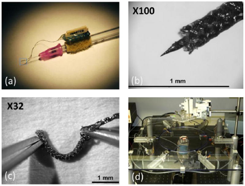
Braided multi-electrode probe (BMEP) with twenty four 12.7um Nichrome wires. (a) BMEP built on a core for insertion, using a 1ml syringe with the electrode interface board (EIB). (b) At 100 magnification, the tip of braid with the tungsten core. (c) The tip of braid without the tungsten core showing flexibility. (d) Braid construction apparatus, operation of which is elaborated in figure 2.
2.1.2. Microwire braiding apparatus
We have developed a novel apparatus for the braiding of ultrafine wires such as the 12.7μm Nichrome wires (see figure 1(d)). The apparatus was designed to allow the braiding of these micro-scale filaments around various types of cores with a unique handoff mechanism consisting of flanged magnetic tubes, rack and pinions and permanent magnets. The design is expandable for more complex braid structures as well.
To understand the basic concept of the tubular braiding process, we take a closer look at the maypole dance which is a form of folk dance from western Europe. In the maypole dance, dancers holding color ribbons attached to the top of the pole perform a circle dance around the pole, which ultimately results in a tubular braid of ribbons over the pole. Before performing the circle dance, dancers are divided into two groups and positioned in a large circle alternating between the two groups (see figure 2(a)). Then dancers in one group circulate clockwise, dancers in the other group circulate counter clockwise and whenever a member of one group meets a member of the other group, they exchange their positions from the inside to the outside of the circle or vice versa. This process is depicted in figure 2(b). As the dancers circulate around the pole, all ribbons wrap the pole in a helical pathway, but the directions of the helical pathway in the two groups are opposite: clockwise and counter clockwise. Every time the two groups cross, one ribbon goes over or under the other depending on the previous state to form a weaving pattern by the dancers’ movement in or out of the circle as shown in figure 2(b). This process interweaves the ribbons in one group with the ribbons in the other group at all crossing points. This results in a tubular braid structure over the pole. For better understanding, figure 2(c) shows the first 3 steps of braiding ribbons over the pole from a top view.
Figure 2.
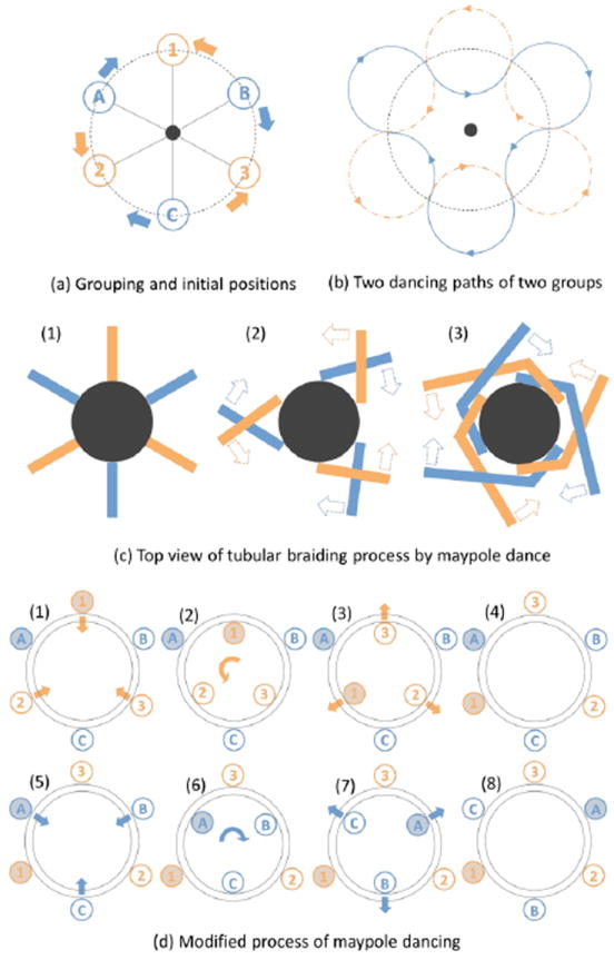
Maypole dancing process. (a) 6 dancers are divided into two groups: the alphabet group and the number group. The members in 2 groups are located alternately in a circle. The center dot is the pole. The solid lines are ribbons held by dancers and attached to the top of pole. The alphabet group will circulate clockwise and the number group will circulate counter clockwise. (b) Two dancing paths are depicted by 2 groups. (c) Top view of the center pole and two different color ribbons attached to the pole to show the tubular braiding process. (1) The initial position of all ribbons (like figure 2(a)). (2) The orange ribbons go over the blue ribbons at first crossing. (3) The blue ribbons go over the orange ribbons at second crossing. (d) The modified maypole dancing process used in the braid apparatus in figure 1(d). (1) The members in the number group are transferred into the carrier which is the inner circle plate. (2) The members in the number group move to the positions of the next member by rotating the carrier 60 degree counter clockwise. (3) The members in the number group are transferred to the outer plate. (4) All members in the number group changed the positions by 60 degree counter clockwise. (5) This time, the members in the alphabet group are transferred to the carrier. (6) The members in the alphabet group move to the positions of the next member by rotating the carrier 60 degree clockwise. (7) The members in the alphabet group are transferred to the outer plate. (8) All members in the alphabet group changed the positions by 60 degree clockwise.
In our design, we modified the maypole dance process. The initial positioning is the same, but instead of two groups circulating in opposite directions at the same time, the groups alternate in their opposite movement around the core. The modified process is depicted in figure 2(d). This is done with two plates: the inner circle plate called ‘carrier’ and the outer plate for positioning. Both plates have ‘shelters’ which are temporal holding positions where flanged steel tubes called ‘movers’ hang. The carrier conveys 3 movers belonging to one group clockwise or counter clockwise at a time. The microwires are attached to a holder above the carrier and are hanging through the movers. Motorized rack and pinions installed under the outer plate transfer the movers from one plate to another by pushing and pulling these with permanent magnets. The exchange of mover positions through the rotation of the carrier and the handoff between the outside and the inside plates, cause the microwires to be braided around a core held at the center. For a single wire to have a full helical pathway in the tubular braid, the process depicted in figure 2(d) needs to be repeated three times. The braiding process is repeated until the desired braid length is achieved; there is no theoretical limit to the braid length. Our apparatus is controlled by a personal computer through a 3-axis stepping motor, and, thus, the whole process is fully automated except for the height adjustment of the wire holder for angle and pitch control in the braid structure. To manufacture a BMEP with 24 wires, we braid 6 groups of 4 wires, i.e., tetrodes (one tetrode per mover).
2.1.3. Electroplating
At the end of manufacturing process, the impedance of each electrode in the braid is lowered to about 500 kΩ from 2-3 MΩ and 100 kΩ for the reference. The electrolyte is a mixed solution of a non-cyanide gold-plating solution (SIFCO 5355) and multi-walled carbon nanotubes (MWCNTs, <8nm diameter, Cheap Tubes Inc.) in distilled water (1 mg/ml concentration). This mixture was chosen to allow us to achieve much lower impedances [28] and improve the recording quality [29, 30]. We used Furguson’s mixing ratio of 1:3 (gold-plating: MWCNTs solution) [28].
Recently, we have developed a fully automated electroplating setup based on a commercially available multichannel electroplating device (Nano Z by Neuralynx Inc.) and a custom-built Matlab program. This setup allows us to automatically perform electroplating to a target impedance on 24 channels and the reference channel within a 2-3 hour time frame. We found that an electrode’s impedance changes when kept in air for a few days after electroplating. Currently, we don’t fully understand why this happens, but found that impedances are still within range a day after electroplating.
2.2. Mechanical tests
The purpose of this test was to quantify the mechanical compliance of tubular braids by measuring their bending stiffness and to compare the results with those of a single 50μm Nichrome wire.
2.2.1. Microelectrodes preparation
To test the braid itself, i.e. the implanted portion, we prepared five different types of probes: single 50μm Nichrome wire (Kanthal RO800), 12 & 24 braided 12.7μm Nichrome wires (Kanthal RO800) and 12 & 24 braided 9.6μm Nichrome wires. Each probe was glued into the tip of a blunt syringe needle and the probes were trimmed to a length of 4 mm.
To test the tether portion of the braid, i.e. the wires from the implant site to the percutaneous connector, we prepared seven different types of electrodes: single 50 μm Nichrome wires in 3, 5 and 10mm lengths, 12 & 24 braided 12.7μm Nichrome wires and 12 & 24 braided 9.6μm Nichrome wires. Super glue was applied to the braid bodies in order for microwires not to unravel and except for a tiny portion most of the braid was cut off. Each tether was pressed between two glass slides at lengths of 3, 5 or 10mm.
2.2.2. Measuring Instruments
To measure bending force, we used a Grass FT03 force transducer which outputs voltage changes relative to applied force and a Grass P122 strain gage amplifier which has a maximum gain of 100k. The smallest measurable force range of the transducer is from 2mg force (19.6μN) to 50g force (490mN). Depending on the force applied, a 10k or 100k gain setting was used. An Inchworm IW811-L microdrive manipulated by an Exfo 8200 controller was used to produce precise electrode bending deflection. To record voltage changes, a Digidata 1322A (Axon Instruments) with a 16-bit A/D converter, a ±10V input range and a 305μV resolution was used.
2.2.3. Measuring bending forces of the electrode braid
The experimental setup is shown in figure 3. The test sequence to measure lateral bending forces of electrode bodies is as follows: First, the test electrode is mounted to the inchworm drive. Second, the electrode is positioned close to the FT03 sensor by manipulating the manual linear stage. Third, through a microscope, the height of the electrode is adjusted until it just touches the right top end of force sensor rod as shown in figure 3(b). Fourth, voltage changes were recorded at 1 kHz sampling rate for about 30 seconds (10s for the base line, 2s for moving 500μm, 8s for the steady state at maximum deflection, 2s for moving back, 8s for the base line). Because we manually operated the Inchworm controller during recording, the recording length and timing were only roughly identical across recordings and samples. A total of ten recording repetitions were performed for each sample.
Figure 3.
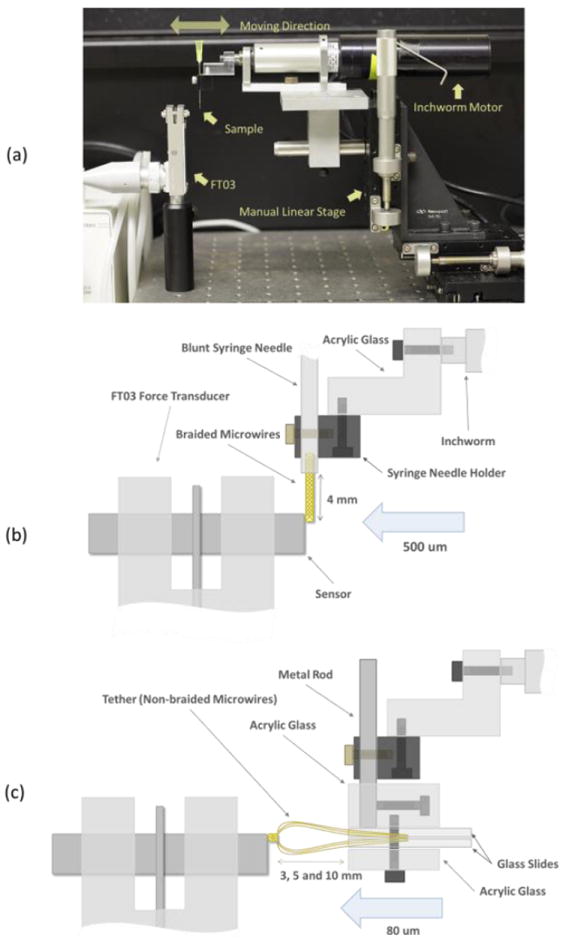
(a) Testing setup. All devices were mounted on an air table. (b) Lateral (bending stiffness) test setup - detailed diagram. (c) Axial stiffness test setup - detailed diagram.
2.2.4. Measuring bending forces of tethers
Two tests were performed: lateral bending and axial compression. For both tests, a custom holder was used for the syringe needle and the slide glasses that hold the tether.
In the lateral bending test, the 50μm single wire sample was directly mounted to the syringe needle holder as seen in figure 3 (b) and braid tether samples were held vertically by the custom holder with an L shape rod, and then the holder set was mounted to the syringe holder. The moving distance of the Inchworm was 500 μm and we followed the above mentioned 5 steps for testing. With braid tether samples the test sequence was repeated 3 times in 3 different lengths (3, 5 and 10mm).
In the axial compression test, all samples were horizontally mounted to a custom holder with a straight rod to the syringe holder as seen in figure 3(c). The moving distance was 80μm and again, we followed the above mentioned 5 steps for testing. The test sequence was repeated 3 times for 3 different lengths (3, 5 and 10mm) of the braid tether.
2.2.5. Data Processing
To convert measured voltage values to corresponding displacement force values, the setup was calibrated by calculating the fitting line of the recorded voltage against known weights. The force transducer was horizontally fixed and 7 known weights (0.05, 0.1, 0.2, 0.3, 0.5, 1 and 2 grams) were hung and the output voltages recorded for 11 s with a 1 kHz sampling rate (3s for the base line, 2s for moving, 3s for the steady state at maximum deflection, 2s for moving back, 1s for the base line). The voltages produced by each weight were recorded 10 times. The recorded data were loaded into Matlab, the average between trials was calculated and the relationship between voltages and weights plotted. To calculate the voltage of a trial, 1000 data points in the first 3 seconds were selected and used to calculate the average base line voltage. Then, 1000 data points at maximum deflection were selected to calculate the steady state voltage corresponding to a particular weight. Because the output of the FT03 doesn’t always start from 0V, the base line voltage was subtracted from the voltage recorded for a particular weight to obtain the actual voltage change. For better accuracy, the average of 10 trials was calculated. The calibration resulted in a linear fit with an R2 of 0.99998 and the following equation to calculate the Force F at a 100k gain
| (1) |
where y is the voltage change.
From Cantilever beam theory with an end load, we can calculate the bending stiffness (BS) as follows:
| (2) |
where F is the bending force, L is the electrode length, D is deflection distance at the end of the electrodes, E is the Young’s modulus and I is the second moment of area.
Given the two equations above, one can convert the measured voltages to bending forces and stiffnesses.
2.3. Surgery and recordings
2.3.1. Probe insertion
To enable insertion into neural tissue without buckling, braiding is done over a stiff tungsten core (figure 1 (b)). This tungsten core is removed after insertion into neural tissue to only leave behind the flexible braid. For this, the top of the tungsten core is glued to the rubber of the piston of a conventional 1 ml syringe. Thus, we can retract the tungsten core from the braid by pulling on the piston. The core is threaded through a blunt 30G syringe needle and its tip prevents the braid from being pulled out of the tissue with the core (see figure 4(a)). The braid is not glued to the core but stays on the core by physical surface friction between the two materials. The braid is held together at both ends by a thin silicone coat applied during manufacturing. After removing the core and the syringe completely, the BMEP is effectively a floating microprobe since its tether is very flexible. The insertion process is depicted in figure 4(a-d). To maximize the compliance of the tether, the loose portion of the wires between the braid and the connector are not tied or bonded together. We believe the flexible probe and tether alleviate tissue damage or stress caused by stiff electrodes during tissue motion.
Figure 4.
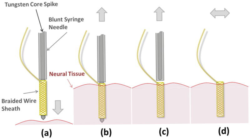
Electrode insertion mechanism design and operation. (a) The BMEP before insertion into the neural tissue. For actual probe, see figure 1(a). (b) The BMEP was inserted into the tissue before removing the stiffening core. (c) The core was removed from within the BMEP before removing the blunt syringe needle, which retains the braided probe in place in the tissue. (d) After removing core, the blunted needle and the syringe set are removed. The BMEP is ready to record left floating in the tissue.
Before testing the probes in vivo, we performed in vitro insertion tests into 0.5% agar gel which has mechanical properties similar to live human brain tissue [31, 32], but also into 1% and 2% agar gel. We confirmed that the tips of BMEPs do not come apart during insertion. However, in the 2% agar gel, the stiffest medium, we observed that BMEPs were slightly retracted from the tip of the core through the insertion and then slowly extended out to the core tip and the intended depth.
We use a commercially available connector board, or EIB, (EIB-27-micro, Neuralynx Inc.) as an interface between the microwires and recording or stimulating devices. The circuit board has an Omnetics nano connector and via for microwire insertion and pinning. After gold pinning, we tie the wires up at the front of the EIB with a 5-0 suture and apply silicone rubber onto the top and bottom of the EIB to protect and insulate the wires and pinned connections.
The BMEP is attached to a 3-axes micromanipulator (WPI, Kite) via a syringe holder and positioned over the insertion site. The 3-axes micromanipulator has a manual one-axis linear stage (Newport, MS-125-X) affixed to allow retraction of the syringe piston after insertion. Just before electrode insertion, the connector board is detached from the syringe body and transferred to a temporal holder close to its final position to minimize stress on the electrode after insertion. A small opening is created in the dura mater and the BMEP is slowly advanced into the neural tissue until the appropriate depth is reached. After probe insertion, the tungsten core is removed from the braid by pulling the syringe piston out and the syringe is removed completely.
2.3.2. Frog Experiment
For spinal cord recording from freely moving bullfrogs, we prepared a 22-channel BMEP with a probe length of 1.5 mm and a tether length of about 6 cm using 12.7μm Nichrome wires. Before implanting the BMEP, the frogs were anesthetized, decerebrated and a laminectomy was performed. The BMEP was chronically implanted into the L2/L3 region of the frog’s spinal cord at a depth of 700 – 1000μm. The connector of the BMEP was mounted on a previously implanted pelvic implant (see figure 8(a)). After recovery, the decerebrate frogs were allowed to move freely on a force platform and neural activity was recorded on all 22 channels through the Cerebus data acquisition system (Blackrock Microsystems). Decerebrate frogs show very vigorous behaviors, close to intact patterns. Simultaneously, electromyograms (EMGs) were recorded from leg muscles to infer motor primitives during prey strike [33, 34]. We repeatedly recorded from the frogs for 5 days after the spinal implant.
Figure 8.
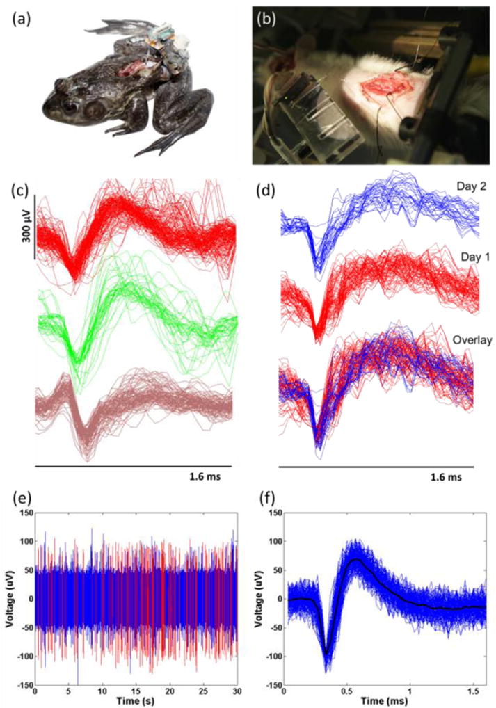
Implanted animals and recording experiments: (a) Chronic decerebrate frog with laminectomy and mounted electrode (freely moving). The frog had a chronic BMEP implanted, which had the 22 channels with 12.7μm Nichrome wires, into the spinal cord. The tether of BMEP was fixed to the muscle with 5-0 silk suture at two positions. (b) Acute decerebrate rat with electrodes in place in spinal cord. The rat had the acute BMEP implanted into the spinal cord. The EIB is on the multiple EIB holder at the left bottom. The golden shining line in the air between the EIB and the spinal cord is the tether of BMEP. In this test, we used a 12 channel BMEP with 9.6μm Nichrome wires. (c) Neural spikes from the data recorded from one freely moving decerebrate frog’s spinal cord. 3 different types of spikes sorted by the K-mean sorting algorithm are shown. (d) We obtained the same types of sorted spikes consistently across 2 consecutive days. (e) The continuous signal and spikes recorded from rat’s spinal cord with the 12 channel BMEP with 9.6μm Nichrome wires. The red lines are the positions of sorted spikes shown in (f). (f) Sorted spikes in the rat. Spikes were sorted by the K-mean sorting algorithm. The average peak-to-peak voltage of the spikes was 166.4μV (at SNR = 5.4).
2.3.3. Rat Experiment
The purpose of this experiment was to record neural activity from the spinal cord during airstepping locomotion evoked by stimulation of the mesencephalic locomotor region (MLR) in decerebrate rats. For this, we used 12-channel BMEPs made of 9.6μm Nichrome wires with a braid length of 1.5mm and a tether length of 8cm. A tungsten electrode was inserted into the brain for MLR stimulation after decerebration and laminectomy, and then the BMEP was inserted into the spinal cord. The rat was mounted on a custom stereotaxic frame and only the head and pelvis were fixed to let the rat’s body and fore & hind limbs move freely. The head was fixed with ear bars and a mouth piece and the pelvis was fixed to a metal bar through a preinstalled, custom pelvic implant. Recording was performed for 30 seconds during MLR stimulation.
3. Results
3.1. Bending forces of microelectrodes
3.1.1. Bending forces of electrode bodies
The averages of the voltage changes recorded during the bending test were calculated and converted to bending forces using equation (1). The bending forces were converted to bending stiffnesses using equation (2). To compare the 50μm single wire with the BMEPs, we calculated the relative compliance ratio (RCR) by dividing the BS of a 50μm single wire by the BS of the BMEP. The results are shown in table 1 and figure 5.
Table 1.
Bending force and stiffness of electrode bodies by 500μm lateral deflection at 4mm.
| Electrode | BFa (mN) | BSa (KPamm4) | RCRb | |
|---|---|---|---|---|
| A | 50μm | 1.55 | 65.98 | |
|
| ||||
| B | 24×12.7μm | 0.41 | 17.39 | 3.79 |
| 12×12.7μm | 0.12 | 5.28 | 12.49 | |
| 24×9.6μm | 0.23 | 10.01 | 6.59 | |
| 12×9.6μm | 0.07 | 3.12 | 21.14 | |
BF:Bending Force, BS: Bending Stiffness
RCR: Relative Compliance Ratio (BS of A / BS of B)
Figure 5.
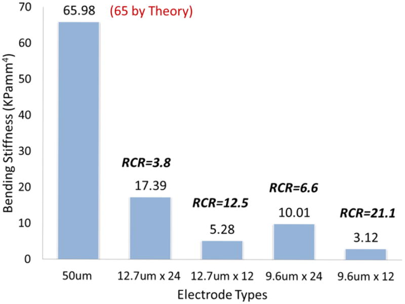
Bar graph of bending stiffness (BS) from the 5 different types of electrodes tested. The values of relative compliance ratio (RCR) shown on the top of each bar are relative values to the reference BS of 50μm single wire (65.98). The theoretically calculated value of the BS of 50μm single Nichrome wire was 65.
As can be seen in figure 6, the RCR of 24 braided 12.7μm wires was 3.8, which means the braid has about 4 times better compliance than a single 50μm wire. The tested braids configurations all had between 4 and 21 times better compliance than the single 50μm wire. Since the outer diameter of a tubular braid is roughly 150-200μm and a braid consists of up to 24 12.7μm wires whose diameter is only four times smaller than a 50μm single wire, the tubular braid structure greatly increases the flexibility of the bundle. The bending stiffness of braids with 24 wires is roughly 3 times that of equivalent braids with 12 wires, whereas the BS of braids with 12.7μm wires is roughly 1.7 times that of equivalent braids with 9.6μm wires. In the case of 50μm wires, the theoretical, calculated value roughly matched the measured value.
Figure 6.
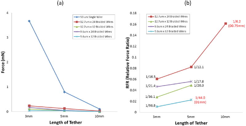
Bending forces of the tether at 3 different lengths by 500μm lateral deflection (a) The graph shows the whole scale including the result from 50μm single wire. (b) Relative force ratio (RFR) from the result in (a). At 10mm, only the sample of 12.7μm × 24 braided wires has the value by the different deflection. Other samples don’t have the RFR values at 10mm because they were not measurable. The values in red color are results by different lateral deflections other than 500μm.
3.1.2. Bending forces of tethers with lateral bending
Bending forces (BFs) were used here to compare compliances since they are related to compliance and do not depend on wire arrangement in the tether. We did not calculate bending stiffness because beam theory was not an applicable approximation in the unbraided portion of the braid. In case of the 50μm single wire, only the BS for the 5 mm sample was measured. The BFs of all other lengths were calculated via equation (2) using the measured BS of the 5mm sample.
Figure 6 shows the measured bending forces. We could not measure the BFs of 10mm long braid tethers with a deflection of 500μm because the forces were below our instrument resolution, and too small to be measured with this setup. This was also true for 12 × 9.6μm braids 5mm length. To still get a reading, the deflection was increased to 750μm for 24 × 12.7μm, 10mm braids and 1000μm for 12 × 9.6μm, 5 mm braids. The 50μm wire required the largest forces to bend but also showed the biggest drop in force for longer wire lengths. Unsurprisingly, the thinner the wires and the less wires were used in the braid, the less force was required to bend the tether. The probes with 24 wires required 2.3 (12.7μm) or 4.5 (9.6μm) times higher forces to bend than the ones with 12 wires for 500μm deflections; the probes with 12.7μm wires required 1.4 (24 wires) to 2.7 (12 wires) times higher forces than the ones with 9.6μm wires.
To compare the compliance of braids to 50μm single wires, we calculated the relative force ratio (RFR) by dividing the BF of a braid tether by the BF of the 50μm single wire (see figure 6(b)). At 3mm tether length, the braid tethers require roughly 17 to 100 times less force for bending than the 50μm single wire. As the tethers get longer, the ratio gets smaller since the force required for the single wire drops much faster that for braids but they remain smaller than the forces for single wires for all lengths measured, by a factor of at least 6.
3.1.3. Bending forces of tethers for axial compression
Figure 7 shows the results from this test. The forces required for axial compression were much higher than for lateral bending. The forces required for axial compression drop less dramatically for longer tether lengths when compared to lateral bending. For a 3mm tether, going from 24 wires to 12 dropped the force by a factor of 2.7 (12.7μm) or 3.6 (9.6μm), whereas going from 12.7μm to 9.6μm wires only reduced the force by a factor of 1.6 (24 wires) or 2.2 (12 wires). The relationship between tether length and force required for axial compression is roughly linear for braid tethers but for the 50μm single wire there is a dramatic drop in force from 5 to 10mm. As can be seen in figure 7(b), a 50μm single wire requires 8 to 86 times larger forces to achieve the same axial compression.
Figure 7.
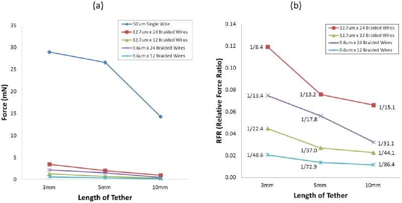
Bending forces of the tether at 3 different lengths by 80μm axial compressing (a) The graph shows the whole scale including the result from 50μm single wire. (b) Relative force ratio (RFR) in relation to 50μm wire from the result in (a).
3.2. Neural recordings from spinal cord
3.2.1. Frog experiment
Spike sorting was performed on the recorded neural data using a K-mean sorting algorithm and the t-distribution algorithm published by Shoham et al. [35]. We found a total of 166 neurons and 46 neurons related to the motor primitives obtained from leg EMGs. Stable recordings could be made from spinal cord intermediate zone for nearly a week in decerebrate frogs as it performed a range of motor behaviors that involved ballistic jumping. Figure 8(b-c) shows samples of six sorted spikes. To calculate signal-to-noise ratio (SNR), we used following equation described by Suner et al. [36].
| (3) |
where A is the peak-to-peak voltage of the average spike waveform and SDnoise is the standard deviation of the noise recorded during a quiet 1-second window between two spikes. The SNRs of sorted clusters ranged from 4 to 7.
3.2.2. Rat experiment
During MLR stimulation, the rat’s back muscles contracted so strongly that it caused arching and evoked stepping in the air. This caused significant movement and stretching and compression of the spinal cord. The BMEP followed the sometimes violent movement of the animal and we successfully recorded neural spikes during that time. The implanted probe and surrounding tissue were microscopically inspected after every recording to ensure that the probe was not dislodged. Figure 8(e) shows the 30-seconds of continuous neural data of a typical channel and the sorted spikes extracted from it. The SNR of the sorted spikes in figure 8(f) was 5.4.
4. Conclusion
All combinations of electrode braids have better mechanical compliance than a single 50μm Nichrome wire. The braid bodies have 4 to 21 times better lateral compliance, and the tethers of the BMEPs have 6 to 97 times better lateral compliance and 8 to 86 times better axial compression compliance depending on the number of wires used and their diameter. Going from 24 to 12 wires in a braid had a bigger impact on compliance in all cases than going from 12.7 to 9.6μm diameter wires.
Apart from their excellent mechanical compliance, the BMEPs allow us to acutely and chronically record single units from the spinal cord of a stepping and jumping animal. They do not get dislodged or seem to damage the tissue significantly when the animal moves but this has to be verified histologically. The SNR of the recorded units in these preliminary experiments ranged from 4 to 7. We have not investigated the impact of different impedances on recording quality.
5. Discussion
Our data show the value and potential benefits of braided probe designs for recording in hostile environments such as spinal cord. The probes provided useful data in these settings.
5.1. Advantages and possible applications of braided probes
The tubular braid structure for multi-electrode probe design has significant potential. It can be easily modified in different ways by combinations of different materials, sizes, shapes, etc. For examples, one can substitute platinum-iridium (Pt/Ir) wires for Nichrome wires for stimulation or combine both in one braid. Braiding wires around any kinds of shape or material form is easily performed by our apparatus. If we braid microwires over a micropipette, this can be used for simultaneous drug delivery and electrical recording or stimulation. If we braid microwires over an optical fiber, it could be used for simultaneous optogenetic light stimulation and electrical recording or stimulation. We have braided 12.7μm wires onto and around several materials, including micropipettes, pulled optical fibers, flat silicone sheets, polyethylene microtubes, 5-0 and 10-0 surgical suture. The braid onto 10-0 suture could be used for micro-scale implantable multi-unit or single unit EMG electrodes for human subjects. In the case of braids onto a silicone sheet, we have successfully recorded multi-channel EMG electrode data in a rat’s abdominal muscles and tested its use on rat’s spinal cord for chronic multi-channel epidural stimulation. Another advantage of BMEPs is that there is theoretically no probe length limitation. We have tried lengths over 10 cm, and it is not difficult to make such probes in lengths of several tens of centimeters. Long BMEP designs could augment deep brain recording or deep brain stimulation (DBS) electrodes. The DBS lead (Medtronics Model 3387/3389) for movement disorder approved by FDA has total 1.27mm outer diameter and 4 Pt/Ir wires are coiled inside the polyurethane tube [37], well suited to fine braid coating sheaths.
5.2. Future directions
Our braid plate design is fully extensible to allow a hexagonal array with handoffs to allow most types of figured braids conceivable for probe construction of many spatial forms and fully leverage the possibilities of textile-based material properties. This framework allows us to control the detailed geometry, mechanics and compliance of probe designs. In terms of developing BMEPs further, laser ablation and cutting are also important. Preliminary tests in cutting 12.7μm Nichrome single wire and ablating the polyimide insulation on the wire body with the Excimer laser are underway by collaboration with a mechanical engineering lab in Drexel. A precise laser system will allow us to make BMEPs having vertical recording sites along the braid in chosen geometries and to control the probe length more precisely. In the immediate future it will also be important to test how the probe body compliance, the tether compliance of current BMEPs and its tubular design in general affect the implanted tissue immunoreactivity. We are now beginning work on neural immunohistology in rats whose brains are implanted with 4 different types of electrodes per brain to explore responses.
In conclusion, braided probes offer possibilities for reliably extending single unit recordings in awake behaving animals into new domains such as spinal cord. The approach may enable new types of prostheses and perhaps more reliable probe designs through textile technologies allowing better impedance matched probes constructed of finer scale wire or other fibrous elements.
Acknowledgments
This work was supported by NIH NS44564, NS54894, NS072651-01 grants and the PA Tobacco Settlement. Patents are pending. Arun Ramakrishnan is the co-inventor of micro-strand braiding apparatus. Dr. Ubong Ime Udoekwere performed the surgery for the rat experiments and Dr. Vitaly Marchenko advised on decerebration issues. Corey Hart advised on spinal recording issues. We appreciate the aid of Dr. Michel Lemay for letting us to use Grass P122 amplifier and power supply for P122.
References
- 1.Carmena JM, et al. Learning to control a brain-machine interface for reaching and grasping by primates. PLoS Biol. 2003;1(2):E42. doi: 10.1371/journal.pbio.0000042. [DOI] [PMC free article] [PubMed] [Google Scholar]
- 2.Velliste M, et al. Cortical control of a prosthetic arm for self-feeding. Nature. 2008;453(7198):1098–101. doi: 10.1038/nature06996. [DOI] [PubMed] [Google Scholar]
- 3.Donoghue JP. Bridging the brain to the world: a perspective on neural interface systems. Neuron. 2008;60(3):511–21. doi: 10.1016/j.neuron.2008.10.037. [DOI] [PubMed] [Google Scholar]
- 4.Babb TL, Kupfer W. Phagocytic and metabolic reactions to chronically implanted metal brain electrodes. Exp Neurol. 1984;86(2):171–82. doi: 10.1016/0014-4886(84)90179-1. [DOI] [PubMed] [Google Scholar]
- 5.Schmidt S, Horch K, Normann R. Biocompatibility of silicon-based electrode arrays implanted in feline cortical tissue. J Biomed Mater Res. 1993;27(11):1393–9. doi: 10.1002/jbm.820271106. [DOI] [PubMed] [Google Scholar]
- 6.Lee K, et al. Polyimide based neural implants with stiffness improvement. Sensors and Actuators. 2004;B(102):67–72. [Google Scholar]
- 7.Richardson RR, Miller JA, Reichert WM. Polyimides as biomaterials: preliminary biocompatibility testing. Biomaterials. 1993;14(8) doi: 10.1016/0142-9612(93)90183-3. [DOI] [PubMed] [Google Scholar]
- 8.Edell DJ, et al. Factors influencing the biocompatibility of insertable silicon microshafts in cerebral cortex. IEEE Trans Biomed Eng. 1992;39(6):635–43. doi: 10.1109/10.141202. [DOI] [PubMed] [Google Scholar]
- 9.Szarowski DH, et al. Brain responses to micro-machined silicon devices. Brain Res. 2003;983(1-2):23–35. doi: 10.1016/s0006-8993(03)03023-3. [DOI] [PubMed] [Google Scholar]
- 10.Seymour JP, Kipke DR. Neural probe design for reduced tissue encapsulation in CNS. Biomaterials. 2007;28(25):3594–607. doi: 10.1016/j.biomaterials.2007.03.024. [DOI] [PubMed] [Google Scholar]
- 11.Zhong Y, Bellamkonda RV. Controlled release of anti-inflammatory agent alpha-MSH from neural implants. J Control Release. 2005;106(3):309–18. doi: 10.1016/j.jconrel.2005.05.012. [DOI] [PubMed] [Google Scholar]
- 12.Zhong Y, Bellamkonda RV. Dexamethasone-coated neural probes elicit attenuated inflammatory response and neuronal loss compared to uncoated neural probes. Brain Res. 2007;1148:15–27. doi: 10.1016/j.brainres.2007.02.024. [DOI] [PMC free article] [PubMed] [Google Scholar]
- 13.Linseman MA, Corrigall WA. Neurophysiological evidence of movement of chronically-implanted fine wire electrodes in recordings of field potentials in hippocampus. Physiol Behav. 1981;26(4):729–33. doi: 10.1016/0031-9384(81)90152-9. [DOI] [PubMed] [Google Scholar]
- 14.Kim YT, et al. Chronic response of adult rat brain tissue to implants anchored to the skull. Biomaterials. 2004;25(12):2229–37. doi: 10.1016/j.biomaterials.2003.09.010. [DOI] [PubMed] [Google Scholar]
- 15.Biran R, Martin DC, Tresco PA. The brain tissue response to implanted silicon microelectrode arrays is increased when the device is tethered to the skull. J Biomed Mater Res A. 2007;82(1):169–78. doi: 10.1002/jbm.a.31138. [DOI] [PubMed] [Google Scholar]
- 16.Nicolelis MAL NEUROSCIENCEnetBASE. CRC methods in neuroscience series. CRC Press; Boca Raton: 1999. Methods for neural ensemble recordings; p. 257. [Google Scholar]
- 17.Davson H, Segal MB. Physiology of the CSF and Blood-Brain Barriers. Boca Raton: CRC Press; 1996. [Google Scholar]
- 18.Söllinger M. Assessment of intracranial dynamics using MRI. Swiss federal institute of technology; Zurich: 2008. [Google Scholar]
- 19.Gilletti A, Muthuswamy J. Brain micromotion around implants in the rodent somatosensory cortex. J Neural Eng. 2006;3(3):189–95. doi: 10.1088/1741-2560/3/3/001. [DOI] [PubMed] [Google Scholar]
- 20.Goldstein SR, Salcman M. Mechanical factors in the design of chronic recording intracortical microelectrodes. IEEE Trans Biomed Eng. 1973;20(4):260–9. doi: 10.1109/TBME.1973.324190. [DOI] [PubMed] [Google Scholar]
- 21.Cui X, et al. Surface modification of neural recording electrodes with conducting polymer/biomolecule blends. J Biomed Mater Res. 2001;56(2):261–72. doi: 10.1002/1097-4636(200108)56:2<261::aid-jbm1094>3.0.co;2-i. [DOI] [PubMed] [Google Scholar]
- 22.Kipke DR, et al. Silicon-substrate intracortical microelectrode arrays for long-term recording of neuronal spike activity in cerebral cortex. IEEE Trans Neural Syst Rehabil Eng. 2003;11(2):151–5. doi: 10.1109/TNSRE.2003.814443. [DOI] [PubMed] [Google Scholar]
- 23.Campbell PK, et al. A silicon-based, three-dimensional neural interface: manufacturing processes for an intracortical electrode array. IEEE Trans Biomed Eng. 1991;38(8):758–68. doi: 10.1109/10.83588. [DOI] [PubMed] [Google Scholar]
- 24.Rousche PJ, Normann RA. Chronic recording capability of the Utah Intracortical Electrode Array in cat sensory cortex. J Neurosci Methods. 1998;82(1):1–15. doi: 10.1016/s0165-0270(98)00031-4. [DOI] [PubMed] [Google Scholar]
- 25.Ward MP, et al. Toward a comparison of microelectrodes for acute and chronic recordings. Brain Res. 2009;1282:183–200. doi: 10.1016/j.brainres.2009.05.052. [DOI] [PubMed] [Google Scholar]
- 26.NeuroNexus. Research Products Catalog. 2012 [Google Scholar]
- 27.Head AA, Ko FK, Pastore CM. Handbook of Industrial Braiding. Atkins and Pears [Google Scholar]
- 28.Ferguson JE, Boldt C, Redish AD. Creating low-impedance tetrodes by electroplating with additives. Sens Actuators A Phys. 2009;156(2):388–393. doi: 10.1016/j.sna.2009.10.001. [DOI] [PMC free article] [PubMed] [Google Scholar]
- 29.Keefer EW, et al. Carbon nanotube coating improves neuronal recordings. Nat Nanotechnol. 2008;3(7):434–9. doi: 10.1038/nnano.2008.174. [DOI] [PubMed] [Google Scholar]
- 30.Baranauskas G, et al. Carbon nanotube composite coating of neural microelectrodes preferentially improves the multiunit signal-to-noise ratio. J Neural Eng. 2011;8(6):066013. doi: 10.1088/1741-2560/8/6/066013. [DOI] [PubMed] [Google Scholar]
- 31.Das R, et al. A benchtop system to assess cortical neural interface micromechanics. IEEE Trans Biomed Eng. 2007;54(6 Pt 1):1089–96. doi: 10.1109/TBME.2007.897139. [DOI] [PubMed] [Google Scholar]
- 32.Howard MA, 3rd, et al. Measurement of the force required to move a neurosurgical probe through in vivo human brain tissue. IEEE Trans Biomed Eng. 1999;46(7):891–4. doi: 10.1109/10.771205. [DOI] [PubMed] [Google Scholar]
- 33.Hart CB, Giszter SF. Modular premotor drives and unit bursts as primitives for frog motor behaviors. J Neurosci. 2004;24(22):5269–82. doi: 10.1523/JNEUROSCI.5626-03.2004. [DOI] [PMC free article] [PubMed] [Google Scholar]
- 34.Giszter S, Patil V, Hart C. Primitives, premotor drives, and pattern generation: a combined computational and neuroethological perspective. Prog Brain Res. 2007;165:323–46. doi: 10.1016/S0079-6123(06)65020-6. [DOI] [PubMed] [Google Scholar]
- 35.Shoham S, Fellows MR, Normann R. Robust, automatic spike sorting using mixtures of multivariate t-distributions. J Neurosci Methods. 2003;127(2):111–122. doi: 10.1016/s0165-0270(03)00120-1. [DOI] [PubMed] [Google Scholar]
- 36.Suner S, et al. Reliability of signals from a chronically implanted, silicon-based electrode array in non-human primate primary motor cortex. IEEE Trans Neural Syst Rehabil Eng. 2005;13(4):524–41. doi: 10.1109/TNSRE.2005.857687. [DOI] [PubMed] [Google Scholar]
- 37.Medtronics. DBS for movement disorders lead kits implant manual. 2010 [Google Scholar]