Abstract
Continuous monitoring of in vivo biological processes and their evolution at the cellular level would enable major advances in our understanding of biology and disease. As a stepping stone towards chronic cellular monitoring, we demonstrate massively parallel fabrication and delivery of 3D multilayer micro-Tags (μTags) into living cells. Both 10 μm × 10 μm × 1.5 μm and 18 μm × 7 μm × 1.5 μm devices containing inductive and capacitive structures were designed and fabricated as potential passive radio-frequency identification tags. We show cellular internalization and persistence of μTags over a 5-day period. Our results represent a promising advance in technologies for studying biology and disease at the cellular level.
Our ability to image living organisms has played a major role in advancing our understanding of biology and disease. However, current technology does not yet allow us to continuously monitor in vivo biological processes and their evolution at the cellular level. These limitations present major barriers to understanding biology more fully and probing the mechanisms of disease.
Considerable progress has been made in the rapidly growing field of intracellular delivery of therapeutic and imaging agents. Since the earliest discoveries of using DEAE-dextran1,2 and calcium phosphate3 as means to deliver exogenous nucleic acids to cultured mammalian cells, a multitude of chemical, physical, and viral transfection techniques have been developed to introduce drugs, proteins, and genes into living mammalian cells. More recently, researchers have studied methods to introduce bioengineered particles into cells, with diameters ranging from a few nanometers to microns4,5,6,7,8,9,10.
Simultaneously, advances in integrated circuit (IC) nanofabrication techniques have driven down the size of active devices (e.g. transistors) and embedded passive components (e.g. capacitors, inductors) on a convergence path with intracellular delivery capabilities11,12. Here we demonstrate massively parallel fabrication of 3D multilayer micro-Tags (μTags) for delivery into cells and show persistence of internalized μTags over a 5-day period. The design, fabrication, release, collection, delivery, and persistence of these μTags are presented.
Results
Design
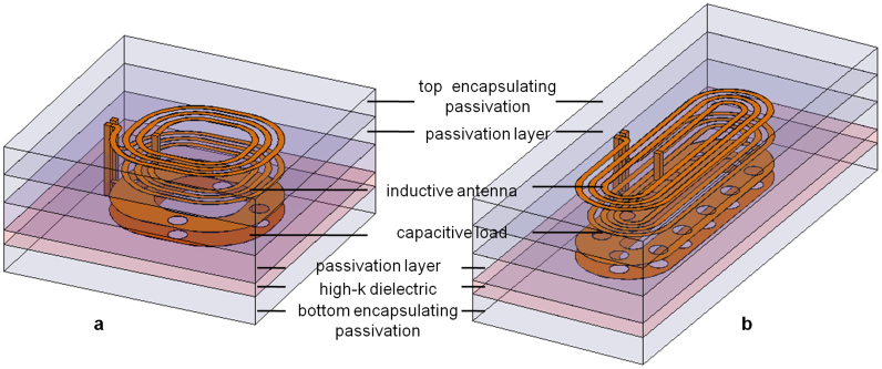
We designed the μTags with passive multilayer structures suitable for use as an inductor (L) and capacitor (C) in parallel. This is a potential platform for RFID (radio-frequency identification) tags. Figure 1 illustrates round and elongated μTag designs of these structures. The top two metal coil layers comprise the inductor while the bottom two metal plates separated by a high-k dielectric form a capacitive load, both of which can be varied. All metal layers are implemented with aluminum (Al) that is at least 100 nm thick to minimize resistance. A hafnium oxide (HfO2) layer that is thinner than 15 nm is used to realize a high-k dielectric for the capacitor. The other metal layers are separated by silicon oxide (SiO2) passivation layers that are at least 150 nm thick to provide sufficient isolation. The round design has lateral dimensions of 10 μm × 10 μm while the elongated version is 18 μm × 7 μm. With at least 250 nm of SiO2 passivation encapsulating the device on the top and bottom side, the μTag has a total thickness of about 1.5 μm.
Figure 1. Illustration of 3D μTag structure stack-ups for (a) round design, (b) elongated design.
Mass fabrication and extraction
The μTags are fabricated using IC microfabrication techniques on standard silicon wafers. The bottom encapsulation SiO2 layer is grown on the silicon wafer via thermal oxidation. The bottom capacitive plate Al layer is deposited via sputtering and patterned using photolithography and dry etching. The HfO2 dielectric layer is then deposited with atomic layer depositions (ALD). The top capacitive plate Al layer is similarly deposited and patterned. The HfO2 dielectric layer is patterned using photolithography and dry etching to expose the vias holes between the bottom plate of capacitance and the first coil metal layer. The SiO2 passivation layer is deposited using low-pressure chemical vapor deposition (LPCVD) and patterned using photolithography and dry etching to expose the via holes between the top plate of capacitance and the second layer of the coil metal. Finally, the top SiO2 passivation layer is deposited to encapsulate the μTag surface. Optical microscopy images of the wafer at various steps are given in Supplementary Figure S1.
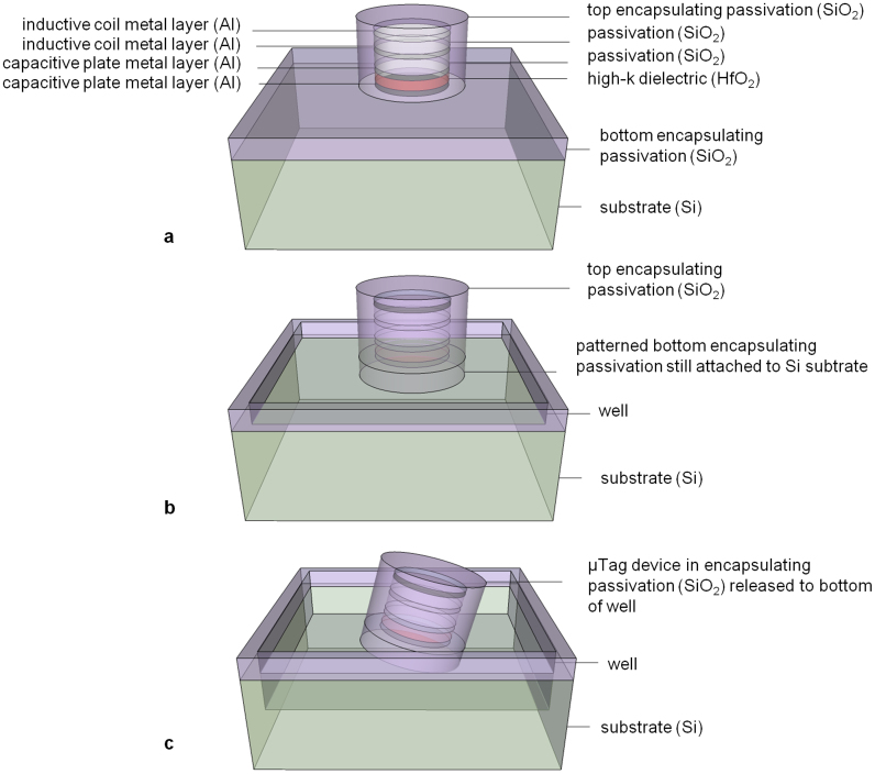
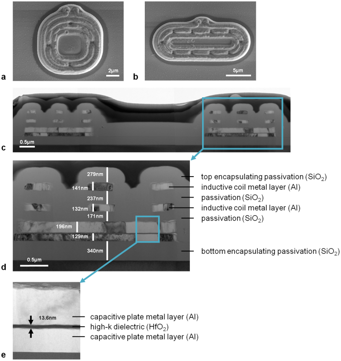
The release process, illustrated in Figure 2, involves patterning the bottom oxide layer into wells of μTag devices to expose surrounding Si. Scanning electron microscopy (SEM) images of μTag devices prior to release are given in Figures 3a and 3b. Figures 3c, 3d, and 3e show the device structure as imaged by a cross-sectional transmission electron microscopy (TEM). Exposed Si is dry etched with XeF2 to remove the layer of Si beneath the devices until the SiO2 encapsulated devices detach and fall into the wells. XeF2 is a vapor phase etch with an etch selectivity of silicon to photoresist, silicon dioxide, and aluminum higher than 100 to 1. Etch rate and etch profiles with this technique can be highly dependent on the substrate surface and loading effects due to sample placement. Due to the small size of μTags, there is a high probability that they will escape from the substrate upon release rather than fall into the wells. Hence, the number of gas flow cycles, etch time for each cycle, and the gas flow rate are carefully adjusted for each sample to prevent μTags from flying off the wafer in the chamber.
Figure 2. Illustration of release process of single μTag device starting with (a) device encapsulated with top SiO2 passivation, (b) well patterning of bottom passivation layer, and (c) device released to bottom of well after Si substrate etch.
Figure 3. SEM images of μTag devices with (a) round design, (b) elongated design; (c) cross-section TEM image of μTag device structure with (d) inset showing layer stack-up and (e) further expanded view of capacitive parallel plate structure.
After the release process, μTag devices in individual wells are flushed with detergent-containing buffer solution to prevent aggregation and manually pipetted into centrifuge tubes. They are then spun down to concentrate the suspended solution of μTag devices with a final concentration of about 50 × 104 devices per mL.
Internationalization
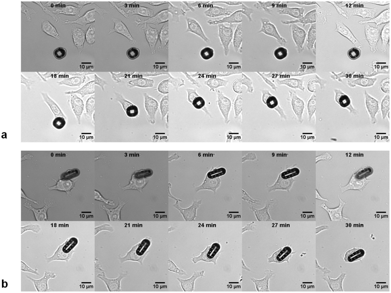
Confluent cultures of mouse macrophages were incubated with μTags (2 × 10⁵ cells per mL with a μTag-to-cell ratio of 1:40) and then imaged at regular time intervals over 30 min to capture internalization. Figure 4 shows time-sequence images of internalization events for both round and elongated μTag devices (Supplementary Videos S2 and S3). Supplementary Figure S4 shows multiple cells with internalized round and elongated μTag devices within the same field. Cross-sectional TEM imaging of a labeled cell in Supplementary Figure S5 further confirms internalization of the μTag device (note some damage to the μTag structure during manual sectioning with a diamond knife).
Figure 4. Time-lapsed bright field microscopy images of cellular uptake of μTag device with (a) round design and (b) elongated design.
Qualitative biocompatibility
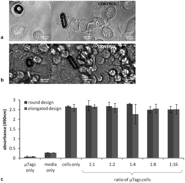
Confluent cultures of mouse macrophages were incubated with or without μTags for 24 h. They were then washed to remove non-internalized μTags as well as any detached dead cells. Images of the internalized μTags and control (no μTag) cultures at day 1 are shown in Figure 5a. All cultures were subsequently maintained over the course of an additional 4 days without passaging. At the end of this 5-day experiment, cultures were again washed and imaged with a vital stain. Time-lapse image sequences of cells with μTags at day 5 (Supplementary Videos S6 and S7) show cell movement, further verifying cell vitality. Snapshots of internalized μTags and control cultures at day 5 are given in Figure 5b.
Figure 5. Bright field microscopy image snapshots of cells with internalized round and elongated μTags and in the positive control group at (a) day 1 and (b) day 5 as well as (c) metabolic activity of cultures incubated with round and elongated μTags and in the positive and negative control groups at day 5, as quantified by absorbance at 490 nm (mean ± s.d.) with a MTS-based assay.
Quantitative biocompatibility
Cell viability of macrophage cultures at day 5 is quantified using a colorimetric MTS-based assay. Absorbance at the 490 nm wavelength is correlated with metabolic activity and thereby, the number of viable cells. Figure 5c illustrates the metabolic activity in cultures with μTags of round and elongated designs at day 5. Data are also shown for the positive control of cell cultures incubated without μTags as well as negative control groups of 1) culture media without cells or μTags and 2) buffer solution containing μTags but no cells or media. The first negative control of culture media shows a baseline background that is consistent with a typical 0.2–0.3 background absorbance level due to the presence of phenol red and exposure to light. Similar levels of cell viability for all μTag-to-cell ratios (from 0 to 1:1) are seen at day 5, with no statistically significant differences (round design: p = 0.3, elongated design: p = 0.7, as determined by one-way ANOVA).
Discussion
A versatile multilayer μTag implementation is presented as first step towards chronic cellular monitoring with passive RFID tags. We have demonstrated mass fabrication and cell delivery of complex 3D multi-layer IC structures, not shown previously. Moreover, these internalized μTags are shown to persist in living cells over the course of 5 days.
Previous work has achieved delivery of single-layer, individually patterned polysilicon particles, with dimensions up to 3 μm × 3 μm × 0.5 μm10. The focused ion beam (FIB) milling they used is time-consuming and not feasible for mass fabrication as it is limited to serial processing of individual pieces in vacuum chambers. In the present study, we have demonstrated massive parallel fabrication and delivery of large and intricate 3D μTags with multiple metal and dielectric layers. Importantly, the IC fabrication techniques used here to create μTags can be extended to produce even more complex circuits for in vivo sensors.
Prior studies have shown uptake of 3 μm × 3 μm × 0.5 μm polysilicon particles by phagocytic D. discoideum cells10 and of 10 μm × 6 μm × 0.5 μm particles by macrophages13. There has also been successful introduction of unpatterned 3 μm × 3 μm × 0.5 μm polysilicon particles into embryos by microinjection14. We have demonstrated uptake by macrophages of even larger cargo in the form of round 10 μm × 10 μm × 1.5 μm μTags as well as elongated 18 μm × 7 μm × 1.5 μm μTags. These macrophages typically have an average diameter of 11 μm and are shown to remain viable after internationalization of these μTags over a 5-day period.
We note that phagocytic cells were used to demonstrate internalization and viability. Macrophages have been shown to take up 5.5 μm diameter spherical particles15, plus there are studies on the role of size and geometry of target particles on their uptake by macrophages16,17. Interestingly, ellipsoidal particles with higher aspect ratios are shown to be more effectively phagocytosed by macrophages along their major axis. For example, macrophages with approximately 7.5 μm radius spherical cell volume are able to uptake ellipsoidal particles with dimensions 3 μm × 3 μm × 14 μm. Other cell types may require more direct delivery methods, such as micro-injection. While we have demonstrated in vitro that macrophages with internalized μTags can remain viable over 5 days, longer studies looking also at the effects on cell function and division, as well as cell migration and survival in vivo, will be needed.
In conclusion, we have fabricated and delivered patterned, multilayer structured μTags into living cells and shown cell viability over the course of 5 days. The passive LC structures formed in our 3D multilayer μTags can be expanded upon to build resonant RFID μTags for chronic cell labeling and monitoring. In particular, the capacitive load can be varied by controlling the high-k dielectric thickness. The inductor design can be also extended to comprise more layers, thereby increasing the inductive component and shifting the resonance to lower frequencies. This resonant frequency can be designed to optimize penetration of RF signal through such lossy transmission media as biological tissues18,19, and thereby improve range. Longer term, this work will open up new avenues for basic biomedical research and advances in the diagnosis and treatment of disease.
Methods
μTag fabrication
To define the 500-nm minimum feature size of the μTags, i-line SPR 955 CM-0.7 resist with ASML (5500/60 model) 5:1 reducing stepper is used for patterning. To clearly pattern the light and dark field images, the exposure energy is adjusted to 90 mJ/cm2 and 100 mJ/cm2 for the capacitance and coil layers respectively. A post exposure bake of 90 s at 120°C is carried out before developing the resist.
The 10-nm HfO2 high-k dielectric layer between the capacitance plates is etched from the contact area by using the Al etch breakthrough recipe in Applied Materials P5000Etcher. The RF power is set to 300 W with gases Cl2 (10 sccm) and BCl3 (40 sccm). The etch rate of HfO2 under these conditions is 10 A/min. The total etch time is 10 min. The release step is done in Xactix e-1 using a XeF2 (xenon difluoride) isotropic silicon etcher. The number of cycles, etch time, and gas flow are individually adjusted for each sample to ensure μTags remain in the wells on the wafer surface upon release.
μTag extraction
Manual extraction was utilized for μTag internalization experiments while batch extraction was used for μTag biocompatibility experiments.
Manual extraction of μTags from individual wells is performed by introducing about 2 μL of phosphate buffered saline (PBS) with 0.05% Tween 20. A 2-μL pipette is used to agitate the suspension by pipetting up and down. The droplet is then extracted into the pipette tip and transferred into a storage tube. Repeating for 25 wells produces a 50-μL μTag suspension with a concentration of about 5 × 10⁵ devices per mL as confirmed through a hemocytometer count.
Batch extraction of μTags is achieved by rinsing the entire wafer with 10 mL of phosphate buffered saline (PBS) with 0.05% Tween 20 and gently sonicating the wafer in solution for 5 min at power level 5 on a VWR 50D Ultrasonic Cleaner. The resulting suspension is transferred into a centrifuge tube. Spinning down at a speed of 1500 rpm (400 × g) for 5 min and removing the supernatant reduces the solution down to a volume of 50 μL with a concentration of about 5 × 10⁵ devices per mL as confirmed through a hemocytometer count.
Cells
The mouse leukemic monocyte macrophage cell line RAW 264.7 (Abcam) is used. They are reconstituted and maintained in Dulbecco's modified Eagle's Medium (DMEM) containing 10% fetal bovine serum (FBS) under standard culture conditions (37°C, 5% CO2, humidified) until confluent.
μTag internalization
The Bioptechs Delta T controlled dish system is used to maintain cultures at 37°C over the observation period on 35 mm outer diameter Delta T3 dishes. In internalization studies, suspended μTags in PBS Tween 20 are added to the cell culture with a concentration of 2 × 10⁵ cells per mL to produce a μTag-to-cell ratio of 1:40 in a final volume of 1.1 mL. Time-lapse video microscopy is performed using a DeltaVision wide-field microscope under bright field illumination with images collected at 30 s intervals for 30 min. Cross-sectional images of the sample confirming internalization of μTags are produced by varying depth of focus by 0.5 μm increments.
Samples for TEM sectioning were prepared by incubating a confluent culture of mouse macrophages in the presence of μTags on 8-well Lab-Tek chambered coverglass. There is a concentration of 1 × 10⁶ cells per mL with a μTag-to-cell ratio of 1:2 in a final volume of 250 μL per well. After 24 h incubation period under standard conditions (37°C, 5% CO2, humidified), the samples are fixed in 2% glutaraldehyde and 4% p-formaldehyde in 0.1 M HEPES buffer (pH 7.2) for 20 min at room temperature. These samples are subsequently postfixed in 1% osmium tetroxide (OsO4), rinsed with double-distilled H2O, stained with uranyl acetate, dehydrated in a graded ethanol series, then infiltrated and embedded in Epon. The samples are manually sectioned with a diamond knife and the sections are finally imaged with a Jeol 1230 TEM.
μTag qualitative biocompatibility
Cultured cells with a concentration of 1 × 10⁵ cell per mL are incubated in the presence of μTag devices on 2-well Lab-Tek chambered coverglass at a μTag-to-cell ratio of 1:20 in a final volume of 500 μL per well. The cells of the same concentration are cultured in the absence of μTag devices in the control group. All cultures are imaged using a DeltaVision wide-field microscope under bright field illumination. Cross-sectional images of the sample confirming internalization of μTags are produced by varying depth of focus by 0.5 μm increments. In addition to cross-sectional imaging, time-lapse video microscopy is used to capture cell movement every 5 s over 3-min periods. Trypan blue is used as a vital stain to corroborate cell viability. Cultures are maintained under standard conditions (37°C, 5% CO2, humidified) without passaging between observations.
μTag quantitative biocompatibility
Confluent cultures of macrophages with a fixed concentration of 1 × 10⁵ per mL cells are incubated with 10 μL of a suspended μTag solution for a final volume of 100 μL per well on a 96-well microplate. A 1:2 dilution series of a suspended solution of round μTags with a starting concentration of 1 × 10⁶ devices per mL systematically varies the number of μTags in each well to form μTag-to-cell ratios of 1:1, 1:2, 1:4, 1:8, and 1:16. This is then repeated for elongated μTags and both sets of samples are created at all concentrations in triplicates. Two sets of triplicate positive control samples consist of a 10 μL PBS Tween 20 solution added to a confluent culture of macrophages at a concentration 1 × 10⁵ cells per mL in a final volume of 100 μL per well. Two sets of triplicate negative controls contain 10 μL PBS Tween 20 solution and 90 μL of cell media (DMEM with 10% FBS) without cells or μTags. We also include additional negative controls in the form of sensors in a 100 μL PBS Tween 20 solution without media at the same 1 × 10⁴ per mL concentration as in the 1:1 wells.
Cultures are maintained under standard conditions (37°C, 5% CO2, humidified) without passaging. At day 5, we use the MTS-based CellTiter 96 Aqueous One Solution Cell Proliferation Assay to characterize cell viability. 20 μL of the MTS and PES containing reagent is added to each well and incubated under standard conditions (37°C, 5% CO2, humidified) for 4 h. The plate is then measured with SpectraMax M2 microplate reader. Three measurements of absorbance at 490 nm are read and averaged. Wells with only PBS solution without assay reagent are used as a blank.
Author Contributions
L.Y.C., M.V.M., H.-S.P.W. and A.S.Y.P. conceived the experiments. L.Y.C. and K.B.P. designed the μTag devices, K.B.P. fabricated them, L.Y.C. extracted them, and H.K. cultured the cells. K.M. provided input on the fabrication and extraction techniques. L.Y.C. and H.K. designed and performed the internationalization and biocompatibility experiments. L.Y.C. and K.B.P. analyzed the data and wrote the paper. All authors reviewed and critiqued the results, and made key revisions to the manuscript. Correspondence and requests for materials should be addressed to L.Y.C.
Supplementary Material
Supplementary Information
Supplementary Video S2
Supplementary Video S3
Supplementary Video S6
Supplementary Video S7
Acknowledgments
We thank Jon Mulholland, John Perrino, and Lydia-Marie Joubert of the Cell Sciences Imaging Facility at Stanford for their expert advice and technical assistance. We also thank J Provine and He (Linda) Yi for assistance in SEM and TEM analysis and discussions about FIB during the course of this work. This work is supported in part by the Seed Grant of the Stanford Center for Integrated Systems and the W.M. Keck Foundation through the W.M. Keck Foundation Faculty Scholar Award to H.-S.P.W. Fabrication of the μTag was performed at the Stanford Nanofabrication Facility, a node of the National Science Foundation funded National Nanotechnology Infrastructure Network (NNIN).
References
- Vaheri A. & Pagano J. S. Infectious poliovirus RNA: A sensitive method of assay. Virology 27, 434–436 (1965). [DOI] [PubMed] [Google Scholar]
- McCutchan J. H. & Pagano J. S. Enhancement of the infectivity of simian virus 40 deoxyribonucleic acid with diethylaminoethyl-dextran. J. Natl. Cancer Inst. 41, 351–357 (1968). [PubMed] [Google Scholar]
- Graham F. L. & van der Eb A. J. A new technique for the assay of infectivity of human adenovirus 5 DNA. Virology 52, 456–67 (1973). [DOI] [PubMed] [Google Scholar]
- Levy R., Shaheen U., Cesbron Y. & See V. Gold nanoparticles delivery in mammalian live cells: a critical review. Nano Reviews 1, 4889 (2010). [DOI] [PMC free article] [PubMed] [Google Scholar]
- Akin D. et al. Bacteria-mediated delivery of nanoparticles and cargo into cells. Nat. Nanotechnol. 2, 441–449 (2007). [DOI] [PubMed] [Google Scholar]
- Soman N. R., Marsh J. N., Lanza G. M. & Wickline S. A. New mechanisms for non-porative ultrasound stimulation of cargo delivery to cell cytosol with targeted perfluorocarbon nanoparticles. Nanotechnology 19, 185102 (2008). [DOI] [PMC free article] [PubMed] [Google Scholar]
- Lin J. et al. Rapid delivery of silver nanoparticles into living cells by electroporation for surface-enhanced Raman spectroscopy. Biosens. Bioelectron. 25, 388–394 (2009). [DOI] [PubMed] [Google Scholar]
- Seo W. S. et al. FeCo/graphitic-shell nanocrystals as advanced magnetic-resonance-imaging and near-infrared agents. Nat. Mater. 5, 971–976 (2006). [DOI] [PubMed] [Google Scholar]
- Terashima M. et al. Human ferritin cages for imaging vascular macrophages. Biomaterials 32, 1430–1437 (2011). [DOI] [PMC free article] [PubMed] [Google Scholar]
- Gomez-Martinez R. et al. A. Intracellular silicon chips in living cells. Small 6, 499–502 (2010). [DOI] [PubMed] [Google Scholar]
- Bohr M. The evolution of scaling from the homogeneous era to the heterogeneous era. IEEE Int. Elec. Dev. Mtg., 1.1.1–1.1.6 (2011). [Google Scholar]
- Lee B. & Wong H.-S. P. NiO resistance change memory with a novel structure for 3D integration and improved confinement of conduction path. Proc. Int. Symp. VLSI Techol., 28–29 (2009). [Google Scholar]
- Fernandez-Rosas E. et al. Intracellular polysilicon barcodes for cell tracking. Small 5, 2433–2439 (2009). [DOI] [PubMed] [Google Scholar]
- Fernandez-Rosas E. et al. Internalization and cytotoxicity analysis of silicon-based microparticles in macrophages and embryos. Biomed. Microdevices 12, 371–379 (2010). [DOI] [PubMed] [Google Scholar]
- Gonzalez O., Smith R. L. & Goodman S. B. Effect of size, concentration, surface area, and volume of polymethylmethacrylate particles on human macrophages in vitro. J. Biomed. Mater. Res. 30, 463–473 (1996). [DOI] [PubMed] [Google Scholar]
- Champion J. A. & Mitragotri S. Role of target geometry in phagocytosis. Proc. Natl. Acad. Sci. U.S.A. 103, 4930–4934 (2006). [DOI] [PMC free article] [PubMed] [Google Scholar]
- Champion J. A., Walker A. & Mitragotri S. Role of particle size in phagocytosis of polymeric microspheres. Pharm. Res. 25, 1815–1821 (2008). [DOI] [PMC free article] [PubMed] [Google Scholar]
- Poon A. S. Y., O'Driscoll S. & Meng T. H. Optimal frequency for wireless power transmission into dispersive tissue. IEEE Trans. Ant. Propag. 58, 1739–1750 (2010). [Google Scholar]
- Kim S., Ho J. S., Chen L. Y. & Poon A. S. Y. Wireless power transfer to a cardiac implant. Appl. Phys. Lett. 101, 073702 (2012). [Google Scholar]
Associated Data
This section collects any data citations, data availability statements, or supplementary materials included in this article.
Supplementary Materials
Supplementary Information
Supplementary Video S2
Supplementary Video S3
Supplementary Video S6
Supplementary Video S7


